Worklog Ashida Wii-First Portable

Joined
Oct 25, 2021
Messages
18
Likes
10
First of all, thanks so much Wesk for putting so much work into the Ashida, and everyone at 4Layers for their work, as well as this community as a whole.
This is my first project so I don't really know how to go about this whole forum thing
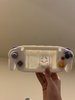
I was originally going to paint the case purple but I ended up really liking how the white looked, I am still not sure whether I should get custom buttons and sticks so it can be more uniform, i think white and grey, black, or even white would be cool. Thoughts?

IMG_2517.jpg


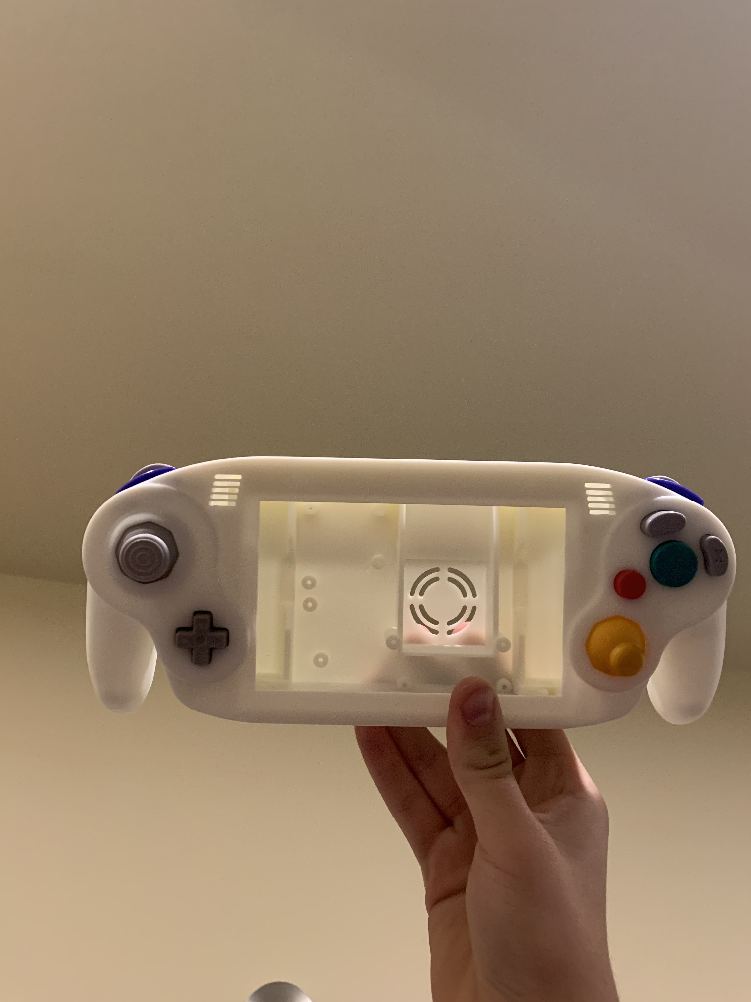
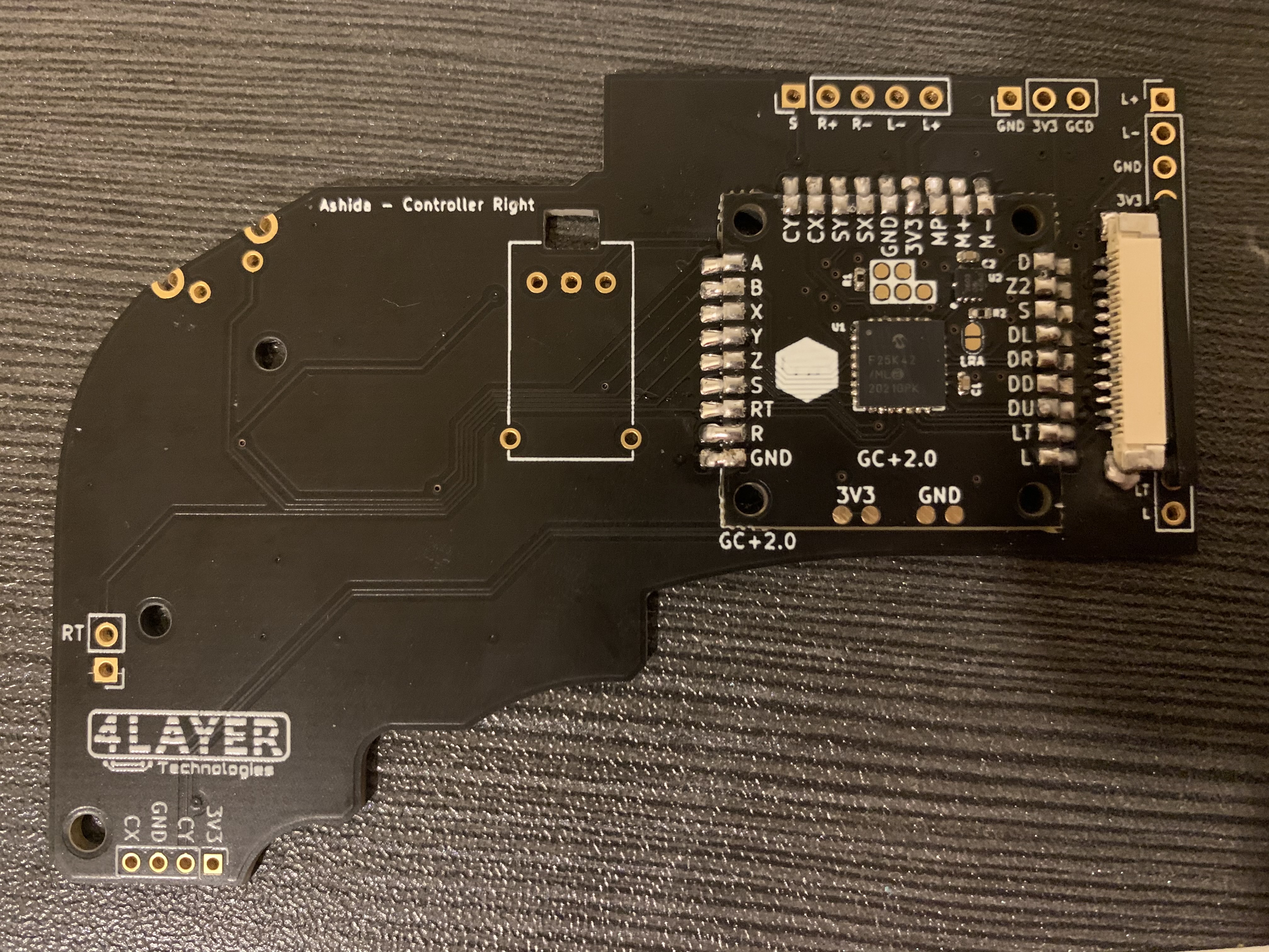
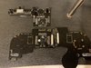
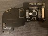
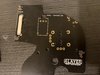
This is my progress so far, I am going to work on the batteries and other boards tomorrow. I am missing the volume part until it gets delivered. I need solder wick before I can move the components from my controller to the pcbs but that should be here on monday at the latest.

IMG_2518.jpg


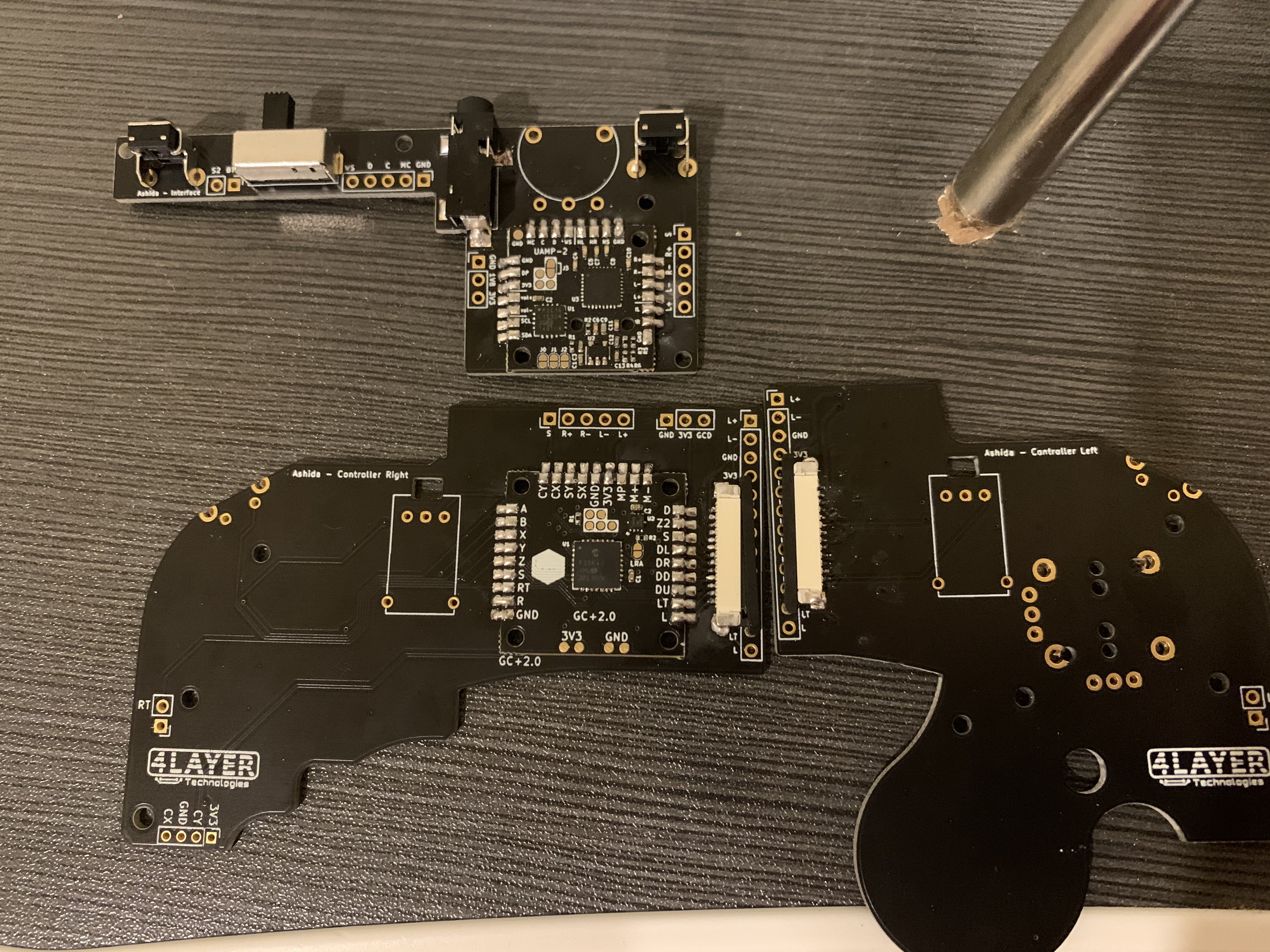
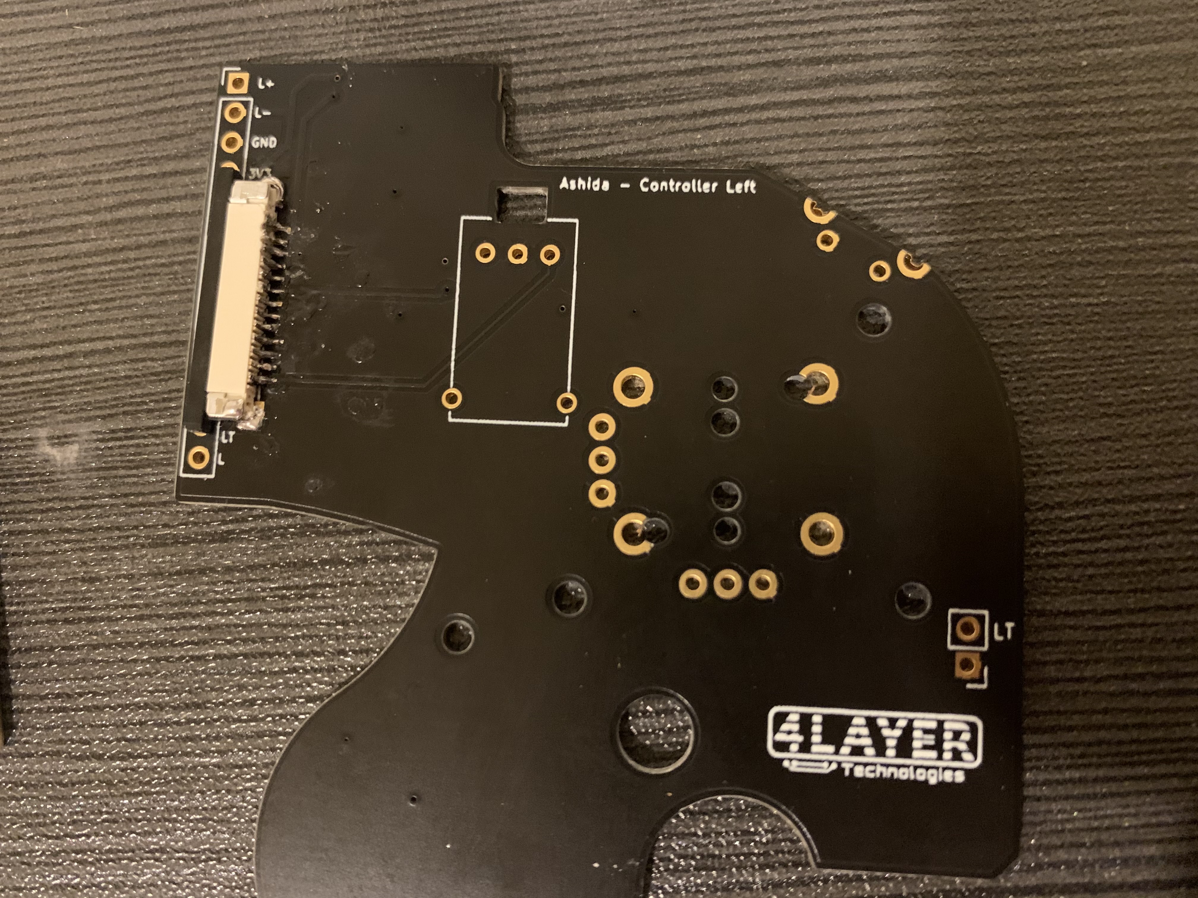
I think I might have messed up the soldering on one or both of the ribbon cable connectors, once I figure out how to use a multi-meter I am going to test them

IMG_2520.jpg
IMG_2521.jpg

:)
 

Attachments

Joined
Oct 25, 2021
Messages
18
Likes
10
Quick questions: I looked around but was unsure how the u10 emulation works. Would you recommend using this feature? If so, my understanding is that you wire from the pms u10 solder point, then to the point on the wii board where the actual u10 wire goes? Is this accurate or no? (Nvm found solution) Secondly I saw a recommendation on another post to replace the resistor array, is the resistor array on the wii motherboard, or is it something you need to add yourself? Or is it built into the 4layer boards. Lastly: Is there a guide anywhere that helps with wiring (vga if that makes a difference) displays to the wii? I vaguely remember seeing something somewhere but im not sure
 
Last edited:

Gman

RTFDS
Staff member
.
.
.
.
.
Joined
Feb 25, 2016
Messages
1,437
Likes
2,887
Quick questions: I looked around but was unsure how the u10 emulation works. Would you recommend using this feature? If so, my understanding is that you wire from the pms u10 solder point, then to the point on the wii board where the actual u10 wire goes? Is this accurate or no? (Nvm found solution) Secondly I saw a recommendation on another post to replace the resistor array, is the resistor array on the wii motherboard, or is it something you need to add yourself? Or is it built into the 4layer boards. Lastly: Is there a guide anywhere that helps with wiring (vga if that makes a difference) displays to the wii? I vaguely remember seeing something somewhere but im not sure
The resistor array is on the wii motherboard. You dont need to replace it unless you have mechanically and visually destroyed it. Resistors usually dont just die on their own, especially higher resistance ones that would need voltage not possible in our devices to fry
 
Joined
Oct 25, 2021
Messages
18
Likes
10
Thanks for the help!

Another question. This is my solder for 3v on the PMS and I was just unsure if this is acceptable or if it needs to be two seperate solder points? What I did in this photo was split my wire into 3 sections, thread one through each point, and solder it all together, will that mess things up?
 

Attachments

Stitches

2 and a Half Dollarydoos
Staff member
.
.
Joined
Feb 5, 2017
Messages
3,817
Likes
3,011
Location
Banana Bender Land, Australia
Portables
6
Thanks for the help!

Another question. This is my solder for 3v on the PMS and I was just unsure if this is acceptable or if it needs to be two seperate solder points? What I did in this photo was split my wire into 3 sections, thread one through each point, and solder it all together, will that mess things up?
Both 3.3v pads are internally connected, so bigg blobb is fine
 
Joined
Oct 25, 2021
Messages
18
Likes
10
Thanks for the help!

Pretty good amount of progress made
B388FA27-499A-4236-B885-9731C301EB94.jpeg


Now I just need to wait until I have my wii mobo trimmed and for my screen and volume wheel to get here and i can hopefully make a lot more!
A few more questions as well
585EF061-92F7-44A8-8518-B27BA24DD7C2.jpeg

With the 5v point circled, what is that used for? I assume I dont need to use it since i dont think i am using any 5v components but I am unsure
E5D9984D-7EF0-4212-85D9-259BF68E1657.jpeg

also because of difficulty sautering I had to use a magnetic wire for one of the connections between the Uamp and my pms, is that an issue?
Thanks everyone for all the help. This is the most fun i have had in months

edit: also im rather scared to trim my wii, if i go a milimeter or two outside the designated trim line will that cause issues? or should i cut/sand it perfectly to the line?

sorry for all the questions, what are SCD and SCW used for
and last lastly, i have not been using flux, and If i were to get some I would have to order it and it would take about a week, my solder is flux rosin core i believe, will that work? And if I dont use flux what bad things would happen?
 
Last edited:

Stitches

2 and a Half Dollarydoos
Staff member
.
.
Joined
Feb 5, 2017
Messages
3,817
Likes
3,011
Location
Banana Bender Land, Australia
Portables
6
USB runs on 5v, most screens are modded to run on 5v, and your fan might too depending on what you're using.

Magnet wire is fine for data lines, but not suitable for carrying supply voltage or ground connections.

The screen you get will have the VGA pinout printed in silkscreen on the underside of the driver board. You just match up the RGBHV inputs on the screen board to the RGBHV outputs shown in the video section of the trimming guide.

As for the trim itself, the provided lines give a fair bit of leeway in all directions for safety, and you can trim outside the lines no worries if you're concerned. It's good to be precise, but a few mm deviation is fine as long as you don't trim way inside the lines and clip something important like the NAND traces. Sanding doesn't really take off that much mass either, it's primarily to smooth jagged edges and clear away between layer shorts.

For the SC lines, check the Documents tab on the PMS page on 4layertech.com. It has a legend table and a basic diagram for exactly that question. The precise locations of the vias on the Wii are in the trimming guide diagrams.
 
Joined
Oct 25, 2021
Messages
18
Likes
10
08679C81-6386-486C-9139-F9F46860B778.jpeg

i think i just ruined my pms. when wiring scw and sdw some solder got stuck to these two points, one is now disconnected and one of them has solder between the two points and I dont think I can fix it. is there anything I can do?

edit: i think i lost the other one
 
Last edited:

Gman

RTFDS
Staff member
.
.
.
.
.
Joined
Feb 25, 2016
Messages
1,437
Likes
2,887
You'll need to use flux and clean the solder off. those resistors can be replaced with a 4.7k resistor from SCW to 1.8v. You can use a through hole resistor if it is easier for you.

The soldering does not look good I can tell there isnt any flux because the solder has not flowed on the whole pad and looks like it is barely hanging on.
 
Joined
Oct 25, 2021
Messages
18
Likes
10
Okay I will work on that, and I am still waiting on flux to arrive in the mail, I should have waited to work on this

Do I only need a resistor for SCW? I am going to remove the one on SDW as well since I dont think I can salvage it. And how do I know the exact wiring for the resistor, do i just put one end on SCW and the other end on 1.8V? Sorry I really dropped the ball
 
Last edited:

Gman

RTFDS
Staff member
.
.
.
.
.
Joined
Feb 25, 2016
Messages
1,437
Likes
2,887
yes so remove both resistors. wire a 4.7k ohm resistor from scw to 1.8v. and a 4.7k ohm resistor from sdw to 1.8v
 
Joined
Oct 25, 2021
Messages
18
Likes
10
Just finished trimming my wii motherboard and I feel pretty good about the results.

Just wanted to make sure this is okay though, i went a bit outside the lines to be careful
FC129DB9-3ED6-4E0A-AD99-2A3B4628E0F6.jpeg


also i assume this is okay but I just wanted to make sure that these copper traces going through the motherboard wouldnt mess anything up

B551647A-EF7D-4BA6-9CFB-90CF6A3CF8A3.jpeg
 
Joined
Oct 25, 2021
Messages
18
Likes
10
Thanks @Wesk thats really good to hear. I will be cleaning it thoroughly once I pick up some isopropyl alcohol, i accidentally bought 70% which could have been bad
 
Joined
Oct 25, 2021
Messages
18
Likes
10
Luckily I didnt mess up wiring the resistors that I already scewed up. This is sort of a mini update to make sure i did this correctly. I am getting my screen and buttons on monday and will do a much larger update then.
image.jpg

also what voltage of usb-c charger does the ashida support? I have a couple but might need to order one
 

Stitches

2 and a Half Dollarydoos
Staff member
.
.
Joined
Feb 5, 2017
Messages
3,817
Likes
3,011
Location
Banana Bender Land, Australia
Portables
6
Luckily I didnt mess up wiring the resistors that I already scewed up. This is sort of a mini update to make sure i did this correctly. I am getting my screen and buttons on monday and will do a much larger update then.View attachment 19799
also what voltage of usb-c charger does the ashida support? I have a couple but might need to order one
According to the product page, 15V 3A is the highest input configurable through the software. The PD will negotiate with USB-C chargers to get what it wants, and should work with any USB-C compliant supply.
 
Joined
Oct 25, 2021
Messages
18
Likes
10
image.jpg
apparently
i didnt learn my lesson because it happened again, do you know what the function of this resistor is?

edit fixed it with the help of Gman
 
Last edited:
Top