Solved Help with Wii Trim | Black screen on AV out

Joined
Mar 20, 2023
Messages
41
Likes
26
Location
'Murica
Introduction and concern

Hello! I recently decided that I should trim a Wii I had laying around, and make it into a micro game console. I installed letterbomb and then RVLoader (I'll get back to this later). I followed the Wii trimming guide and did an OMGWTF trim on my RVK-CPU-01 motherboard. I used a fiberglass disc on a rotary tool to do the cut, then removed the really rough stuff using a bench grinder. After that I sanded it with 320 grit sandpaper, then 800 grit, and then wet sanding with 800 grit too. I made sure to clean the entire motherboard with 91% IPA twice after the trim, and also delidded it to see if I'd get better temps. After the entire ordeal, I removed U5, cut the trace and removed the 3 SMD components, and then replaced it with U10. And then ran a jumper to the designated spot on the other side. I ordered a RVL PSU from @Morklympious, and confirmed it was outputting the correct voltage on all the rails using my multimeter. After this entire ordeal, I wired the RVL PSU to the board (3.3, 1, and 1.15 volt rails respectively), and also a RVA Cable on the component capacitor. I went to test the Wii trim and..... nothing, but a black screen. My bench PSU was reading a current draw of 300 ma at 5V, yet no activity was appearing on the screen. The CPU die barely rose a few degrees (77f to 83f), same goes for the GPU.

Troubleshooting

I was very confused why there wasn't any video output. The TV for sure detected something, as it went from a "No signal detected" screen to a black screen. I mentioned earlier that I installed RVLoader and softmodded the Wii. I for sure can confirm I installed the homebrew channel and all, but I'm not entirely sure if I properly installed RVLoader. I was in a rush at the time but I still do believe that I installed it. Anyway, I relocated the Wifi and Bluetooth modules according to the guide, but alas... Nothing changed (except maybe a slightly higher power draw). This is my first Wii mod, so I failed to do basic tasks before trimming, such as relocating the U10. I also used a bench grinder for the rough sanding, which sounds like a stupid idea in retrospect. All of these shortcomings are my fault only. I should have known better.

Pictures
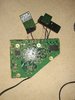
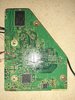
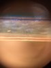
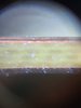
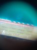
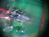
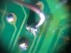
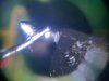
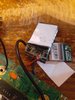
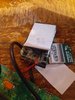
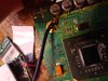
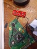
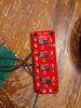
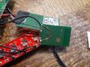
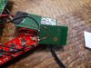
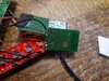
Here are some pictures I took to aid in troubleshooting. Maybe someone here can spot a problem? I took some images with my camera, phone, and using a crappy magnifying attachment on my phone. I can send more if requested. Don't roast me too hard on my trim...

Please note, I added super glue to the WiFI and Bluetooth jumpers, so I couldn't get good pics on those joints.
 

Attachments

CrazyGadget

Crazy Helpful, CrazyGadget
.
Joined
Jun 6, 2020
Messages
607
Likes
875
Location
Downing's Closet
Portables
???
A couple notes
-Did you check your resistances between your voltage lines after trimming? If not, read up on Nold's "Wii Trim Resistances" thread and fill out his table.

-You jumped a considerable amount in grits when sanding. I usually do 120, 220, 320, 400, 600, 800, and 1000. Also wet sanding??? That's.... very strange. Might want to give that an ultrasonic bath in some IPA to clear any crap from under the BGAs.

-Did you check that you're getting 3v3 at your U10 via?

-I'm not sure how short the wires need to be for wifi relocation for it to reliably work, hopefully someone else can chime in about if your relocation looks like it will work.
 

Viilmo

.
Joined
Jun 23, 2021
Messages
208
Likes
92
Location
Germany
Portables
1
I think that the Wifi wires might be a bit too long. Did you patch out Wifi during install? You can still activate it on a game to game basis. To me it sound either like a Wifi or u10 problem
 
Joined
Mar 20, 2023
Messages
41
Likes
26
Location
'Murica
A couple notes
-Did you check your resistances between your voltage lines after trimming? If not, read up on Nold's "Wii Trim Resistances" thread and fill out his table.

-You jumped a considerable amount in grits when sanding. I usually do 120, 220, 320, 400, 600, 800, and 1000. Also wet sanding??? That's.... very strange. Might want to give that an ultrasonic bath in some IPA to clear any crap from under the BGAs.

-Did you check that you're getting 3v3 at your U10 via?

-I'm not sure how short the wires need to be for wifi relocation for it to reliably work, hopefully someone else can chime in about if your relocation looks like it will work.
Thanks for the quick reply, I did indeed try to check the resistances using my multimeter, but it was giving some unreliable results, (GND and 3.3 resistance would go from like 200 ohm to 250k ohm to 20k ohm), I think something is probably just wrong with my meter so I didn't trust those results. I'll post the other voltage rails resistance if I can get reliable readings. As for sanding, I'm very limited in my sandpaper assortment. For wet sanding, I added some distilled water onto the 800 grit WetOrDry sandpaper and used that for the finish, I then wiped off the yucky liquid using some IPA. I sanded at a bit of an angle like I read somewhere, as to reduce the risk of layers shorting. I posted the cross section pictures, they feel smooth and look shiny imo, but there's still a risk of a short happening. I don't have an ultrasonic cleaning machine, best I can really do is compressed air and more IPA. I will shorten the wifi cables and check my U10 and then report back. Thanks!
 
Joined
Mar 20, 2023
Messages
41
Likes
26
Location
'Murica
A couple notes
-Did you check your resistances between your voltage lines after trimming? If not, read up on Nold's "Wii Trim Resistances" thread and fill out his table.

-You jumped a considerable amount in grits when sanding. I usually do 120, 220, 320, 400, 600, 800, and 1000. Also wet sanding??? That's.... very strange. Might want to give that an ultrasonic bath in some IPA to clear any crap from under the BGAs.

-Did you check that you're getting 3v3 at your U10 via?

-I'm not sure how short the wires need to be for wifi relocation for it to reliably work, hopefully someone else can chime in about if your relocation looks like it will work.
1679853242551.png

These are the most reliable readings I got, I guess my board is toast?
 

CrazyGadget

Crazy Helpful, CrazyGadget
.
Joined
Jun 6, 2020
Messages
607
Likes
875
Location
Downing's Closet
Portables
???
You should still read the resistances against your 1v8 line, even if you have the LDO on. The 1v15 line has a short to ground. That could either be from insufficient sanding or some other solder whisk / ball on the board shorting something out. As I previously mentioned, wet sanding was probably a bad idea, because the water mixed with the copper dust from sanding could have gotten under any of the BGA chips (or realistically anywhere else on the board)... That's why I suggested an IPA bath (to try to get underneath those chips).

Your meter jumping around on the 3v3 line is actually a good sign - the voltage lines are not just resistive loads, so there will also be capacitive / inductive loads. The 3v3 line tends to jump around the most where the other show a more static reading. This is completely normal.

I would say do another go-around with all the right grits of sandpaper, then give it an IPA bath and retake your readings.
 
Joined
Mar 20, 2023
Messages
41
Likes
26
Location
'Murica
You should still read the resistances against your 1v8 line, even if you have the LDO on. The 1v15 line has a short to ground. That could either be from insufficient sanding or some other solder whisk / ball on the board shorting something out. As I previously mentioned, wet sanding was probably a bad idea, because the water mixed with the copper dust from sanding could have gotten under any of the BGA chips (or realistically anywhere else on the board)... That's why I suggested an IPA bath (to try to get underneath those chips).

Your meter jumping around on the 3v3 line is actually a good sign - the voltage lines are not just resistive loads, so there will also be capacitive / inductive loads. The 3v3 line tends to jump around the most where the other show a more static reading. This is completely normal.

I would say do another go-around with all the right grits of sandpaper, then give it an IPA bath and retake your readings.
I tried cleaning it with my glorious ultrasonic cleaner (Ziploc filled with IPA attached to a sander attached to a vice)
1679856577344.png
1679856549250.png


But alas, 1.15v is still shorted. I suspect is might a a half cut via that wasn't sanded properly. I'll order assorted sandpaper and report back.
 
Joined
Mar 20, 2023
Messages
41
Likes
26
Location
'Murica
You should still read the resistances against your 1v8 line, even if you have the LDO on. The 1v15 line has a short to ground. That could either be from insufficient sanding or some other solder whisk / ball on the board shorting something out. As I previously mentioned, wet sanding was probably a bad idea, because the water mixed with the copper dust from sanding could have gotten under any of the BGA chips (or realistically anywhere else on the board)... That's why I suggested an IPA bath (to try to get underneath those chips).

Your meter jumping around on the 3v3 line is actually a good sign - the voltage lines are not just resistive loads, so there will also be capacitive / inductive loads. The 3v3 line tends to jump around the most where the other show a more static reading. This is completely normal.

I would say do another go-around with all the right grits of sandpaper, then give it an IPA bath and retake your readings.
Alright, so I re-sanded the edges with 20 grit,120 grit, 220 grit, 240 grit, 320 grit, 400 grit, 600 grit, 800 grit, 1000 grit, and 2000 grit sandpaper. I gave it a bath in IPA and distilled water. And 1.15 is still shorted! I have no idea what the problem is. I'm guessing my board is fried...
 

Stitches

2 and a Half Dollarydoos
Staff member
.
.
Joined
Feb 5, 2017
Messages
3,819
Likes
3,011
Location
Banana Bender Land, Australia
Portables
6
Alright, so I re-sanded the edges with 20 grit,120 grit, 220 grit, 240 grit, 320 grit, 400 grit, 600 grit, 800 grit, 1000 grit, and 2000 grit sandpaper. I gave it a bath in IPA and distilled water. And 1.15 is still shorted! I have no idea what the problem is. I'm guessing my board is fried...
That happens quite often, Wiis just dying for no discernible reason
 
Joined
Mar 20, 2023
Messages
41
Likes
26
Location
'Murica
That happens quite often, Wiis just dying for no discernible reason
You should still read the resistances against your 1v8 line, even if you have the LDO on. The 1v15 line has a short to ground. That could either be from insufficient sanding or some other solder whisk / ball on the board shorting something out. As I previously mentioned, wet sanding was probably a bad idea, because the water mixed with the copper dust from sanding could have gotten under any of the BGA chips (or realistically anywhere else on the board)... That's why I suggested an IPA bath (to try to get underneath those chips).

Your meter jumping around on the 3v3 line is actually a good sign - the voltage lines are not just resistive loads, so there will also be capacitive / inductive loads. The 3v3 line tends to jump around the most where the other show a more static reading. This is completely normal.

I would say do another go-around with all the right grits of sandpaper, then give it an IPA bath and retake your readings.

I bought 2 more 4 layer Wiis and 6 broken wiimotes for 28$, After doing the same process (except the delid and this time masking it off), It works!

1680465063477.png
 
Joined
Mar 20, 2023
Messages
41
Likes
26
Location
'Murica
I just wanted to bring a bit of closure to this thread. I decided to open up my Hantek 2D42 recently to see if there were internal issues. You see, when I probed a resistor with a known resistance of 10-100 ohms, it would say "0 ohms". When I tried a 1k ohm resistor, it said "19.76k ohms". I think I found out what the problem was.
1686330973677.png

Pic not mine but it was the exact same thing, caused by measuring high voltage on ohm mode

R14 and R15 had blown up. These connect directly to pins on the DMM chip so I knew this had to be what was causing it. Fortunately, other people online had a similar issue and one guy even probed his own meter for reference, R14 is a 10K resistor and R15 is a 1k Resistor. I desoldered them and went to Shank's super thread to see if there were any available resistors of the same value. I did find a few 10k and 1k resistors and desoldered them from a cutout Wii motherboard that I had for scraps. After tinning the bare traces due to the pads coming off, I successfully soldered the harvested resistors. Low and behold, I get proper resistances now! The first trim I made (the one I made this post about) has now become more of a testing, donor board. However, I read the resistances as such:

1.8v: 40 ohms
1.15v: 59 ohms
1v: 224 ohms

I'm very happy I was able to fix the issue, I can now accurately probe resistances on trims!
 
Last edited:
Top