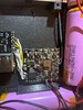
You have way too much exposed wire on almost all of these connections. Something is very likely to short when you button it up later. You only need a few mm of exposed and tinned wire to make a connection to a PCB. I can sense @Stitches getting hives.
A lot of these connections look to be "cold jointed" as well. Which will increase resistance and drop voltage to the Wii board.
Are you using a quality flux when soldering? Are you using a rosin core or leaded solder?
What temp is your soldering iron set to?
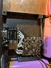
I personally would agree with your fear of powering that on. I would not power the portable up until you've removed and replaced all those solder connections with much less exposed wire to remove the risk of shorting and damaging components
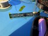
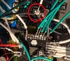
Also. What is that?
A lot of these connections look to be "cold jointed" as well. Which will increase resistance and drop voltage to the Wii board.
Are you using a quality flux when soldering? Are you using a rosin core or leaded solder?
What temp is your soldering iron set to?
I personally would agree with your fear of powering that on. I would not power the portable up until you've removed and replaced all those solder connections with much less exposed wire to remove the risk of shorting and damaging components
Also. What is that?
")