Whats this? Shank actually being responsible and updating his worklog for once? A rare sight to behold.
Anywho, A lot of this project has been tentative and experimental. I don't like sharing info I'm not sure about. A lot of this stuff is unsure, because nobody has ever really made a virtual boy portable before.
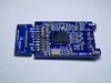
So first up today, we have the virtual boy's controller. Like the NES and SNES, the Virtual Boy controller is just a shift register, specifically 16 bits. While I could have just wired up to two 8 bit shift registers, I wanted to add a few more features, and push myself to learn code. I originally tried to implement the entire shift register within the microcontroller, but the interrupts within the chips weren't fast enough. So instead I had to to have the chip function as a "man in the middle" between the buttons and the shift register. This let me control what inputs get passed along to the shift registers, enabling features like button remapping and additional features activated by various button presses. Wiring up 16+ inputs and 16+ outputs and probing everything became a huge mess, so I developed and assembled this development board! It features dissconnect-able LEDs so I can see which bits are activated, and lots of easily accessible stuff to test things. I did a few oopsies, so the switches needed to be soldered on sideways, and I had to convert the QFP into a QFN for it to fit. With
@CrashBash's help we wrote the foundation for the code that would run on the final board.
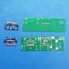
Once that was completed, I ordered and assmebled the actual PCBs. Crash and I spent several all nighters debugging this one.
We also modifed the code of the U-Amp to have analog volume controls. Crash and I went crazy working on it for a few nights, and eventually gave up and just used
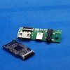
@StonedEdge's code, which worked quite well. The Uamp just looks like a Uamp, but heres a pcb I designed to ount the analog volume control wheel
The code of the PMS was also modified to pull the auxiliary pin when the battery reached red level, allowing me to trigger the virtual boy's on-screen low battery indicator when the PMS reads a low voltage. No picture caus its just a PMS.
I also designed a PCB that will let me mount the Virtual Boy ports to the case without using any glue.
Test print. Everything fits nicely and snaps shut with 3d printed snap fits on the edges. The goal is to have this build be completely glue free.
The servo emulator is a tiny25 that tricks the console into thinking the servo motor is present, because without it, the console wont boot. I tried programming the hex on a SMD version for about a week, but could NOT get it to work for some reason. The chip+board was too thick to fit, so I had to wire it up by hand. Even broke a leg and had to carve into the body to solder to the inside of the leg. But it works, and its stable. Good enough
Now comes the fun part. The 60 pin cart slot needed to be rewired by hand.
AND she boots
In the mean time, more test prints
Lookin snazzy.
Got my roommate and resident ape with a knife Bassline25 to resin cast me some forbidden jolly rancher buttons. All I had to do was offer him free exposure and shoot him with a nerf bazooka
These were just my test prints. I wanted my final print to use multi-material 3d printing to be more virtual-boy like. Heres my final mockup of the design:
My friend TheMitch22 AKA Mitch 3D is a 3d printing wizard with multi material printing. Heres his first test print he gave me:
Now doesn't that look nice! But hes been refining it and made it look even better. With this print, I did some wet sanding to see how it behaves. Little to no color shmearing, and the seams disappear with sanding. This was just 100 grit wet sanding. With some ascending grit and clearcoat, the white color should be gonezo.
Here's with a little water applied to show how what it should look like.
Anyway, yea thats an update. Working as fast as I can. Hope to have it done and the video posted by the end of the year. Thanks for your patience