Question Short to ground on 1.8 V line

Status
Not open for further replies.

Beans

.
Joined
Jul 2, 2020
Messages
12
Likes
2
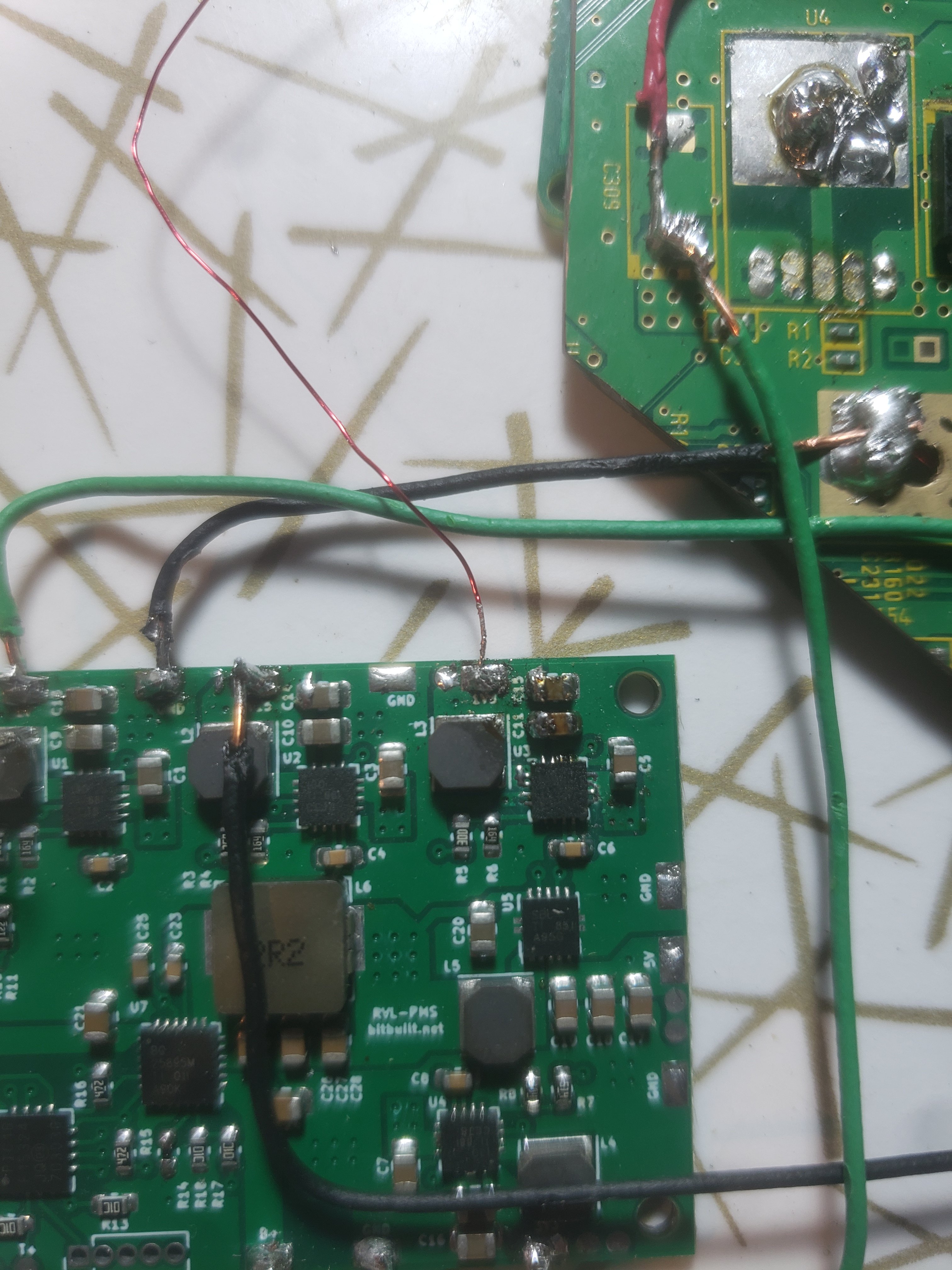
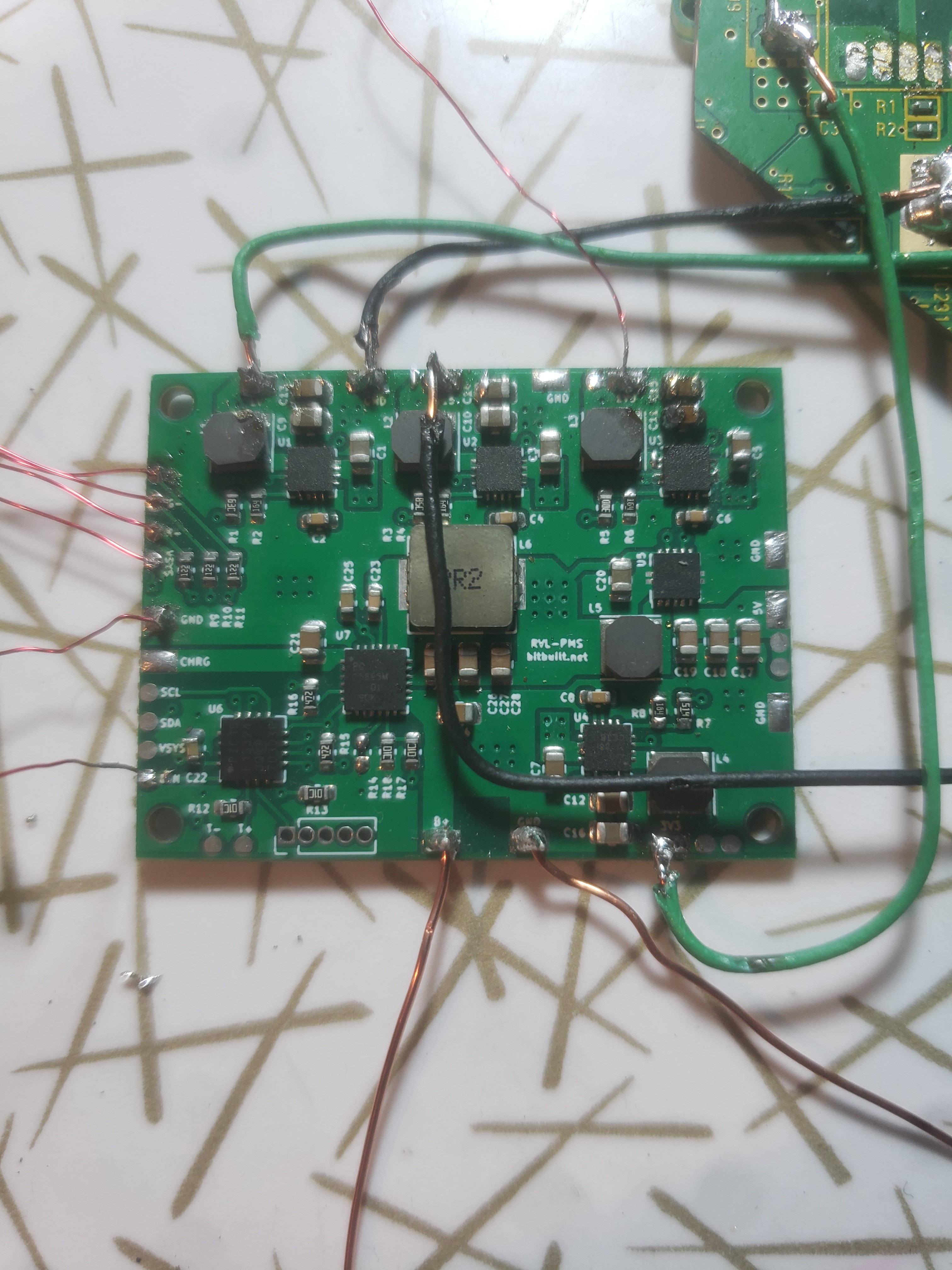
Story time: I trimmed the board, relocated U10, and connected voltages to the board from the PMS. The board booted, to my delight. But then, disaster struck. I was considering removing the LDO to save some room in my case, and so I was probing with my multimeter to find where the 1.8 V output was. I think I accidentally bridged the 3.3 V input pin and the 1.8 V output pin, because I heard a sound not unlike an arc from static electricity. Afterwards, the board didn't boot... So I removed the LDO, and connected 1.8 V from the PMS to the Wii directly. Now, the board still doesn't boot. The PMS puts out 1.8 V like a dream, but when I connect a wire to the Wii, the voltage shorts to ground I believe. I read about 0.05 V on the 1.8 V pad. I can't find the short. Resistance to ground on that voltage line is about 36 ohms if I'm correctly measuring. I know the board looks gross in the pictures, but I've since cleaned it to no avail. If anyone can provide some guidance, that would be great. Thanks.
20200902_184152.jpg

20200902_184146.jpg

20200902_184142.jpg
20200902_184136.jpg

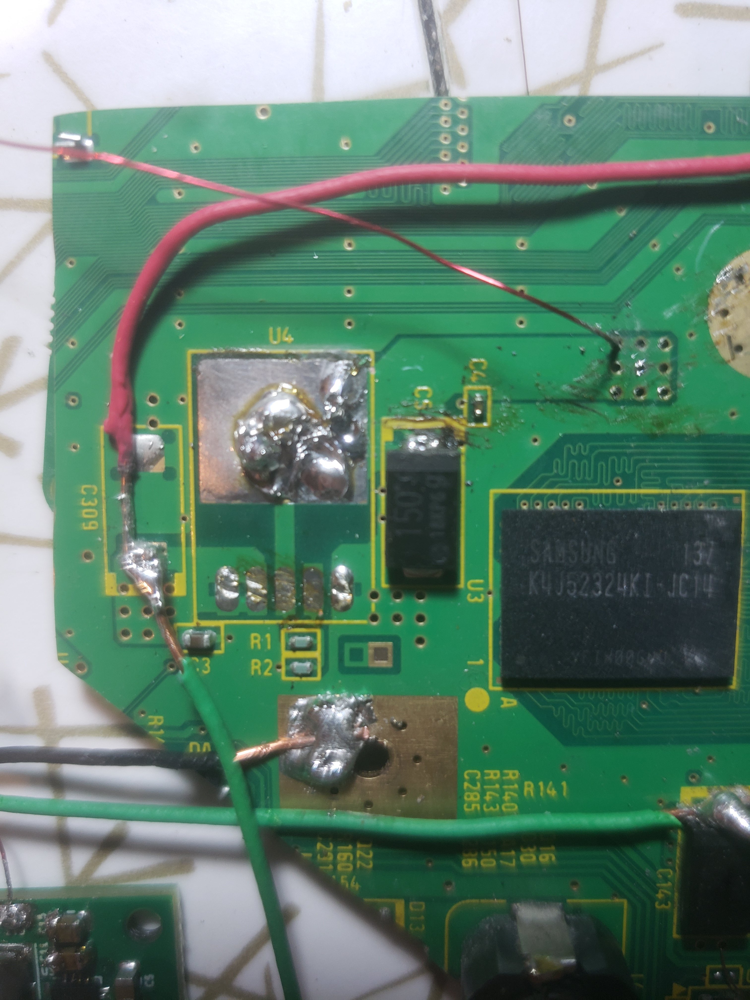
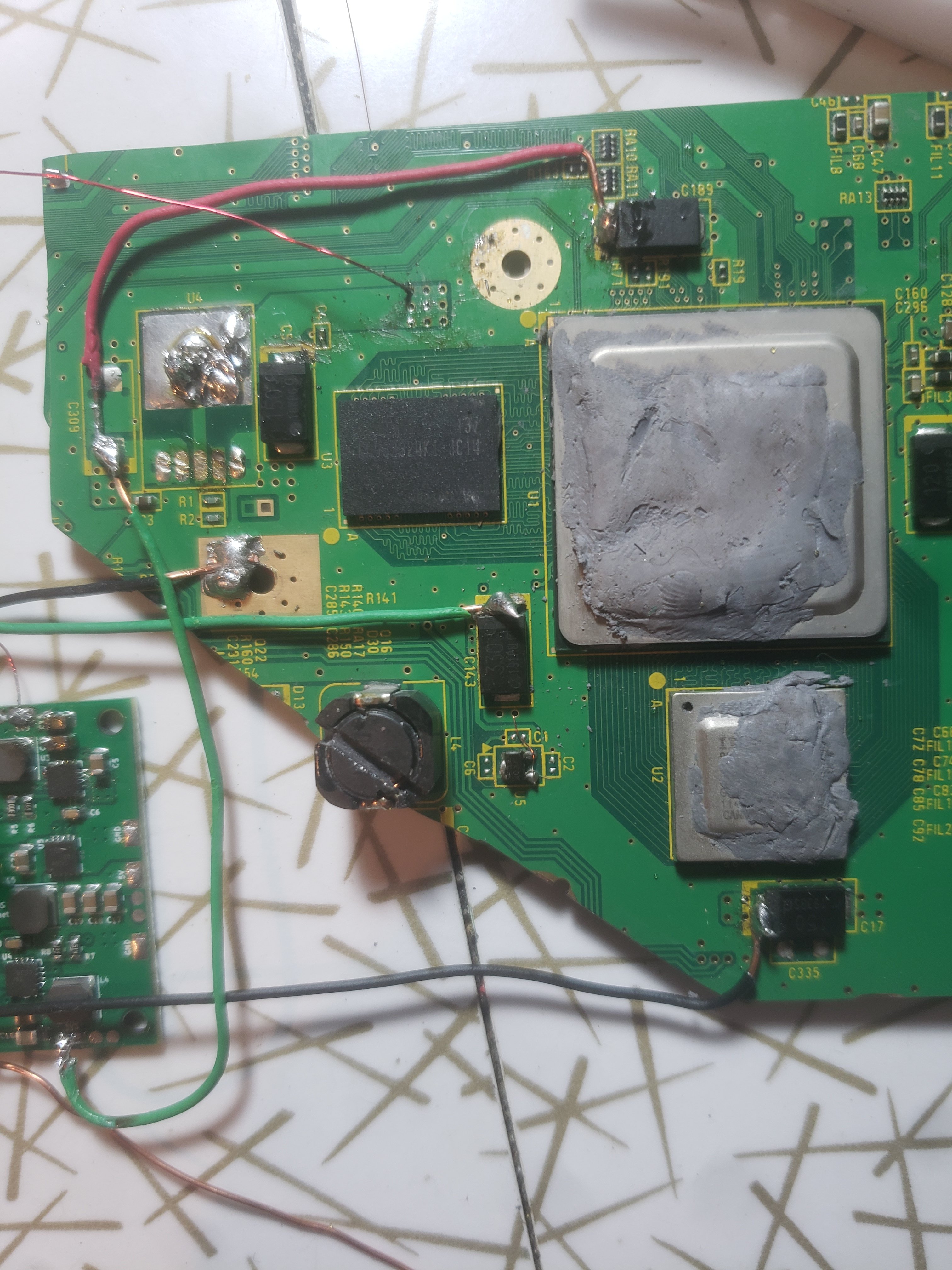
Edit: I've tried connecting 1.8 V to the LDO pad, the capacitor (?) right next to it, and the 9 vias nearby. All short...
 

CrazyGadget

Crazy Helpful, CrazyGadget
.
Joined
Jun 6, 2020
Messages
607
Likes
871
Location
Downing's Closet
Portables
???
Two things right off the bat:
1: You *cannot* use magnet wire for any lines carrying power. You need at least 22awg stranded wire. I'm not sure how thick the wire you are currently using is, but it's making me pretty anxious.
2: You have way too much wire exposed for *all* of your solder points. You should only have enough wire exposed to connect to the joint, no more. Having that much wire exposed is likely the cause of something shorting if it's not actually your board. I recommend stripping your wire, tinning it, then trimming the exposed part to the minimum needed length.
In addition, did you sand your board's edges with 220, 320, 400, 600, and 800 grit sandpaper? It is required to ensure there are no shorts on the board itself. You can verify the proper resistances between the voltage rails with the following guide: https://bitbuilt.net/forums/index.php?threads/wii-trim-resistances.2602/

Hope some of this helps!
 

CrazyGadget

Crazy Helpful, CrazyGadget
.
Joined
Jun 6, 2020
Messages
607
Likes
871
Location
Downing's Closet
Portables
???
Sorry for double posting, but here are some issues:
Screenshot_20200903-052423_Chrome.jpg

On your wii, these look like they could be some serious shorts, 3v3 to gnd on the left, and 3v3 to any of the pins on the components that wire may be touching.

Screenshot_20200903-052246_Chrome.jpg

Your PMS also looks a bit concerning. It looks like you may have lifted a capacitor, and lost a resistor, as well as burning some of 2 inductors (I think?).

Looking at your Wii mobo, I'm guessing it's fried, but it's still worth disconnecting everything and checking the resistances between your voltage rails. A tip for next time: always triple check this stuff before applying power! It only takes one zap to kill a board.
 

Stitches

2 and a Half Dollarydoos
Staff member
.
.
Joined
Feb 5, 2017
Messages
3,815
Likes
3,009
Location
Banana Bender Land, Australia
Portables
6
Two things right off the bat:
1: You *cannot* use magnet wire for any lines carrying power. You need at least 22awg stranded wire. I'm not sure how thick the wire you are currently using is, but it's making me pretty anxious.
2: You have way too much wire exposed for *all* of your solder points. You should only have enough wire exposed to connect to the joint, no more. Having that much wire exposed is likely the cause of something shorting if it's not actually your board. I recommend stripping your wire, tinning it, then trimming the exposed part to the minimum needed length.
In addition, did you sand your board's edges with 220, 320, 400, 600, and 800 grit sandpaper? It is required to ensure there are no shorts on the board itself. You can verify the proper resistances between the voltage rails with the following guide: https://bitbuilt.net/forums/index.php?threads/wii-trim-resistances.2602/

Hope some of this helps!
Sorry for double posting, but here are some issues:
View attachment 13935
On your wii, these look like they could be some serious shorts, 3v3 to gnd on the left, and 3v3 to any of the pins on the components that wire may be touching.

View attachment 13936
Your PMS also looks a bit concerning. It looks like you may have lifted a capacitor, and lost a resistor, as well as burning some of 2 inductors (I think?).

Looking at your Wii mobo, I'm guessing it's fried, but it's still worth disconnecting everything and checking the resistances between your voltage rails. A tip for next time: always triple check this stuff before applying power! It only takes one zap to kill a board.
Everything this man said, plus you may have some conductive debris under the Wii's BGA chips. If you have compressed air, give them a good long puff on all sides, and then fix that wiring.
 

Tony39

.
Joined
Apr 27, 2022
Messages
17
Likes
0
Stop necro-bumping old threads, and please translate your posts to english.
Tempo della storia: ho ritagliato la scheda, trasferito l'U10 e collegato le tensioni alla scheda dal PMS. Il tabellone si è avviato, con mia grande gioia. Ma poi, il disastro ha colpito. Stavo pensando di rimuovere l'LDO per risparmiare un po' di spazio nel mio case, quindi stavo sondando con il mio multimetro per trovare dove fosse l'uscita da 1,8 V. Penso di aver accidentalmente collegato il pin di ingresso da 3,3 V e il pin di uscita da 1,8 V, perché ho sentito un suono non dissimile da un arco causato dall'elettricità statica. Successivamente, la scheda non si è avviata ... Quindi ho rimosso l'LDO e ho collegato direttamente 1,8 V dal PMS al Wii. Ora, la scheda continua a non avviarsi. Il PMS emette 1,8 V come un sogno, ma quando collego un filo al Wii, credo che la tensione vada in cortocircuito verso terra. Ho letto circa 0,05 V sul pad da 1,8 V. non riesco a trovare il corto La resistenza a terra su quella linea di tensione è di circa 36 ohm se io' m misurare correttamente. So che la tavola sembra disgustosa nelle foto, ma da allora l'ho pulita senza successo. Se qualcuno può fornire una guida, sarebbe fantastico. Grazie.
View attachment 13928
View attachment 13929
View attachment 13930View attachment 13931
Modifica: ho provato a collegare 1,8 V al pad LDO, il condensatore (?) proprio accanto ad esso e le 9 vie nelle vicinanze. Tutto corto...
[/CITAZIONE]
Salve dove compro la pcb 1v 3.3 1.8v grazie
 

Stitches

2 and a Half Dollarydoos
Staff member
.
.
Joined
Feb 5, 2017
Messages
3,815
Likes
3,009
Location
Banana Bender Land, Australia
Portables
6
Please stop necro-bumping several year old threads. If you have questions, please ask it in a recently made thread or post your own thread.

Also, this is an english only forum. Please translate your messages to english before posting.

/Thread Locked
 
Status
Not open for further replies.
Top