Worklog HDMI Alt mode over USB-C board

Heuic

.
Joined
Dec 17, 2020
Messages
49
Likes
53
Location
Enumclaw, Washington
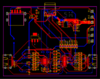
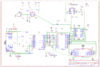
So I just finished the rough draft for a board which I am designing and it should feature:
-A single USB-C port
-Internal USB access
-HDMI through USB-C
-PD-Charging for PMS2
- And a HMDI multiplexer to switch the HDMI signal between the internal screen and the USB-C port.

I'm hoping that someone with more PCB design experience could look over my design and see if there is any major issues.
 

Attachments

Heuic

.
Joined
Dec 17, 2020
Messages
49
Likes
53
Location
Enumclaw, Washington
Well after redesigning the whole thing again I figured out that it was impossible to get the TUSB1046 to work with HDMI alt mode so I looked for alternative solutions and stumbled across LT6711A by Lontium which converts HDMI to DP alt mode. So I got in contact with their team and they are helping me out now but in order to have PD charging on the same USBC port I need to find a PD controller which satisfies these requirements: When CC1 is detected, GPIO is low; When CC2 is detected, GPIO is high, Outputs DP_HPD, and Switches DP from 2 to 4 lane through GPIO.
So I was wondering if anyone knows of any PD controllers that might satisfy these requirements
I was looking at the TPS65987D by TI, which has flip controll pin designed to work with TUSx46 series chips, but am still unsure wheather it does this " CC1 is detected, GPIO is low; When CC2 is detected" or opposite. So ill look into when im able to
Any help is appreciated
 

Heuic

.
Joined
Dec 17, 2020
Messages
49
Likes
53
Location
Enumclaw, Washington
Well, I finally finished the third and hopefully final iteration of my design and have ordered all the parts, spending about 300-400 bucks on tools and supplies. I still have to wait for them to arrive and then test them so hopefully they work ( fingers crossed). Once I get these working I'll probably start selling them as I can't open source the design (its under NDA). If I make a new iteration I think it would be fun to add support for Gamecube controllers and do 2 lane display port with the other 2 lanes used for GameCube controllers on the USB 3 lines, but that would take a bit more research and IDK if that's actually even possible yet or not.

I'd just like to give a big thanks to @loopj @Y2K and especially @YveltalGriffin for their help and answering my questions in the discord ( I go by bruised cucumber in discord).
 

Heuic

.
Joined
Dec 17, 2020
Messages
49
Likes
53
Location
Enumclaw, Washington
Just soldered the topside of a couple of boards together, still finishing the bottoms on them as there are a lot of passives there. Hand-placing all those 0402 capacitors is a real tedious job though:'( 
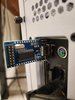
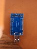
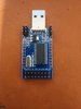
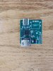
and took me forever. I attached some photos of its relative size. it's 35.4*39.1mm which is just slightly bigger than the PMS 2's 34.5*32.3mm.

photo_2024-03-19_18-14-07.jpgphoto_2024-03-19_18-14-10.jpg
 

Heuic

.
Joined
Dec 17, 2020
Messages
49
Likes
53
Location
Enumclaw, Washington
Hi so I just got my I2C programmer and its CH341b based, but when I plug it into my PC the programmer doesn't turn on or detect the LT6711a. As this is my first time messing around with programmable IC's I was wondering if anyone here with more experience could help me out. IDK if there's some custom firmware that I need to download or if it doesn't work with windows based systems. Any help is appreciated. Thanks
 

JMCD

.
Joined
Feb 18, 2024
Messages
45
Likes
33
Location
UK
Hi so I just got my I2C programmer and its CH341b based, but when I plug it into my PC the programmer doesn't turn on or detect the LT6711a. As this is my first time messing around with programmable IC's I was wondering if anyone here with more experience could help me out. IDK if there's some custom firmware that I need to download or if it doesn't work with windows based systems. Any help is appreciated. Thanks
Hi, silly question but did you install the driver for the USB UART bridge?

https://www.wch-ic.com/downloads/CH341SER_EXE.html

Awesome project by the way!
 

Heuic

.
Joined
Dec 17, 2020
Messages
49
Likes
53
Location
Enumclaw, Washington

Attachments

JMCD

.
Joined
Feb 18, 2024
Messages
45
Likes
33
Location
UK
No I hadn't:blush:
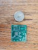
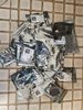
, but I just installed and tried it but the programmer still won't turn. Like in the photo, I attached the onboard LED isn't even on, so I think this programmer just arrived dead.
No need to blush, I've had times they've worked with native drivers and times I've had to force feed windows a driver
 

Heuic

.
Joined
Dec 17, 2020
Messages
49
Likes
53
Location
Enumclaw, Washington
Does it have a EN pin that needs a jumper maybe?
I don't see one Cleary marked but its plausible that one of the pins is that since the descriptionsays it can switch between modes but no other info other than that. Really my problem is I can't find anything to read up on to understand this thing, especially since i got it from aliexpress. Idk if maybe you guys know where some data sheets are. But thanks anyway
 

Attachments

Stitches

2 and a Half Dollarydoos
Staff member
.
.
Joined
Feb 5, 2017
Messages
3,848
Likes
3,026
Location
Banana Bender Land, Australia
Portables
6
The images on this site suggest that yours should indeed have come with some jumpers https://reversepcb.com/ch341a-programmer/

By the looks of it, one of them defines the communication protocol, and the others define the operating voltage
 
Top