
thedrew
.
- Joined
- Sep 27, 2016
- Messages
- 416
- Likes
- 896
I've been tinkering with the N64 on and off for a few months, think I'll start a worklog. Not sure what will come out of this, but hopefully a portable or maybe something that could help others.
I've really enjoyed motherboard redesigns, a nice engineering puzzle for soothing the mind. So here's my take on the N64.
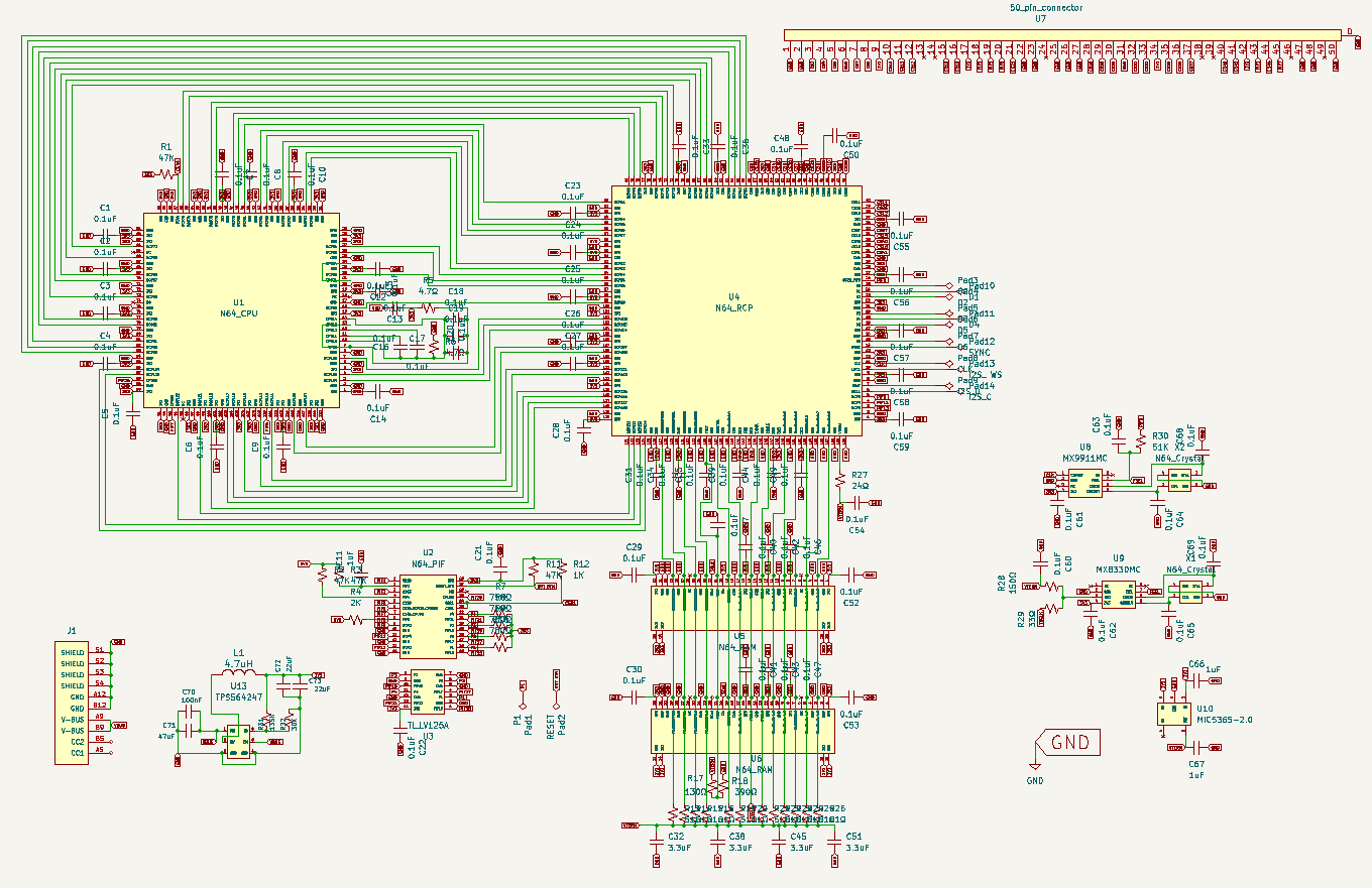
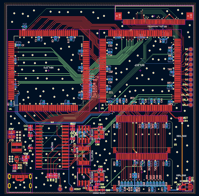
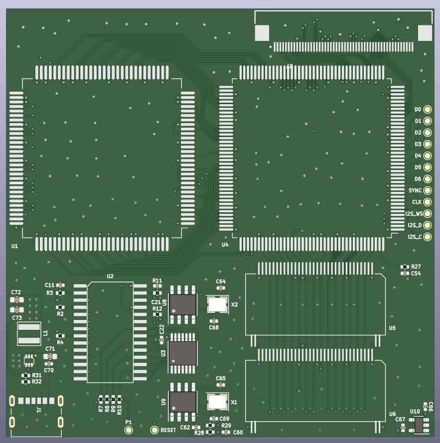
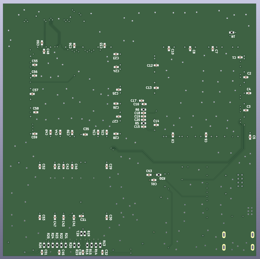
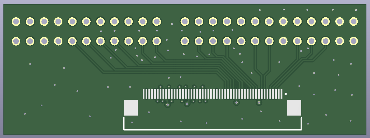
I definitely threw ground vias in an organized chaos at the end. I cross referenced this board with different revisions of the N64 as well as the compendium and seems to be okay.
I am replacing the through hole crystals with SMD crystals of the same value to see if that will work. Yveltal also gave the idea of replacing both MX clock generators (1 dual clock generator on later revisions) with programmable oscillators for a smaller footprint which I plan on testing in the future once I confirm functionality with this redesign first.
Still figuring out what to do about the video out but have tested a couple options.
The Pico DVI N64 project (https://github.com/kbeckmann/PicoDVI-N64) is super cool but doesn't look great as there are color banding issues. To be fair, it is more so a proof of concept as opposed to a final product. Don't have any pictures to show for this option since I won't be going this route.
Also there is the Hispeedido N64 Digital HDMI (https://www.aliexpress.com/i/3256805447859074.html) solution which is a great price and actually looks pretty good, just wish there was a scanline setting. Only draws 0.25w @ 3.3v! The circuit is simple, so would be easy to implement on board with the N64 core to have an all in one. I'm considering this option. It outputs a 720p image and I'm testing it on a 720p monitor in 4:3 mode. Here are some photos:
Stock
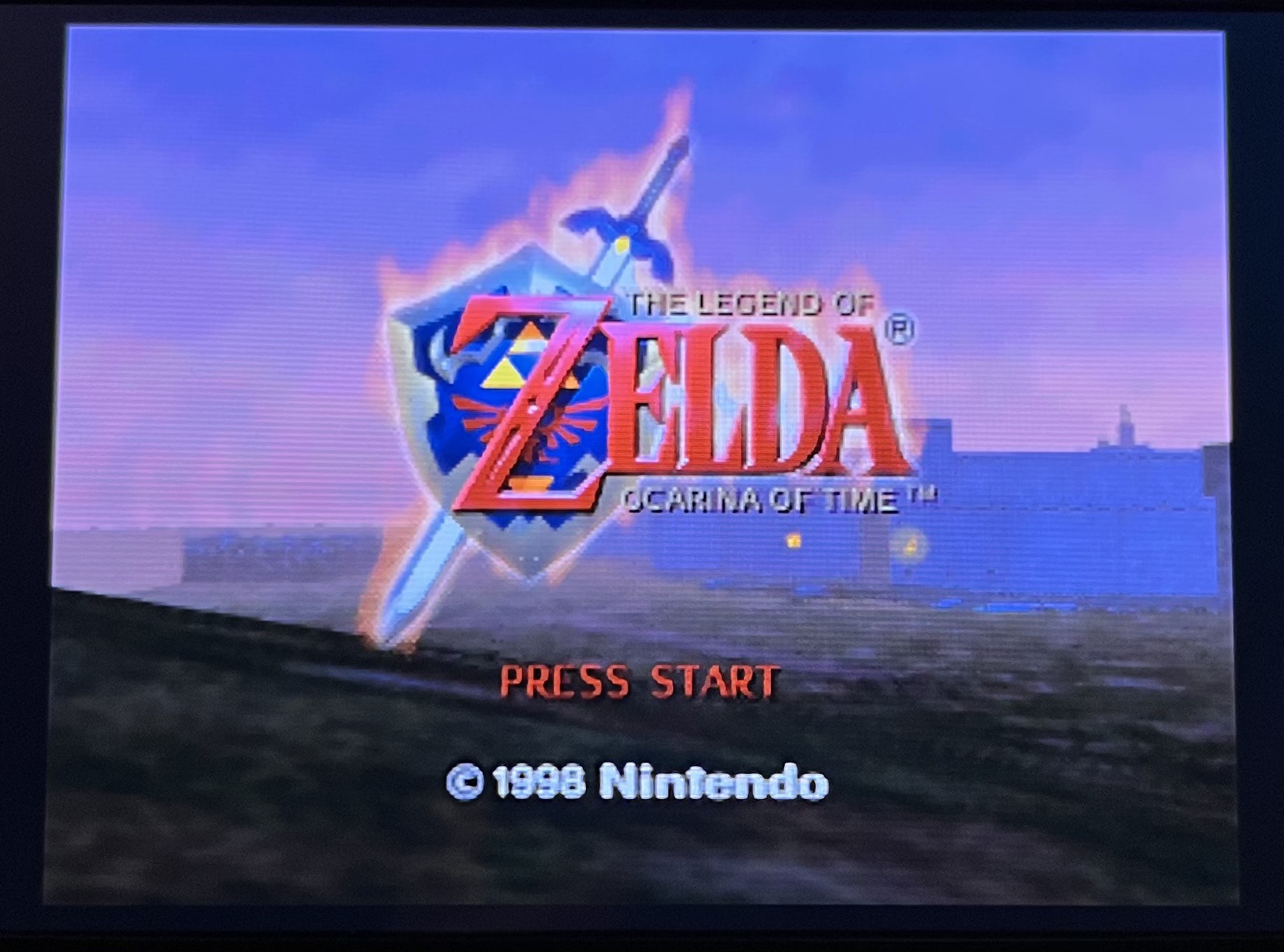
With no anti aliasing patch (using https://github.com/mrdemkin/N64noAAPatcher) which sharpens but makes dithering more apparent.
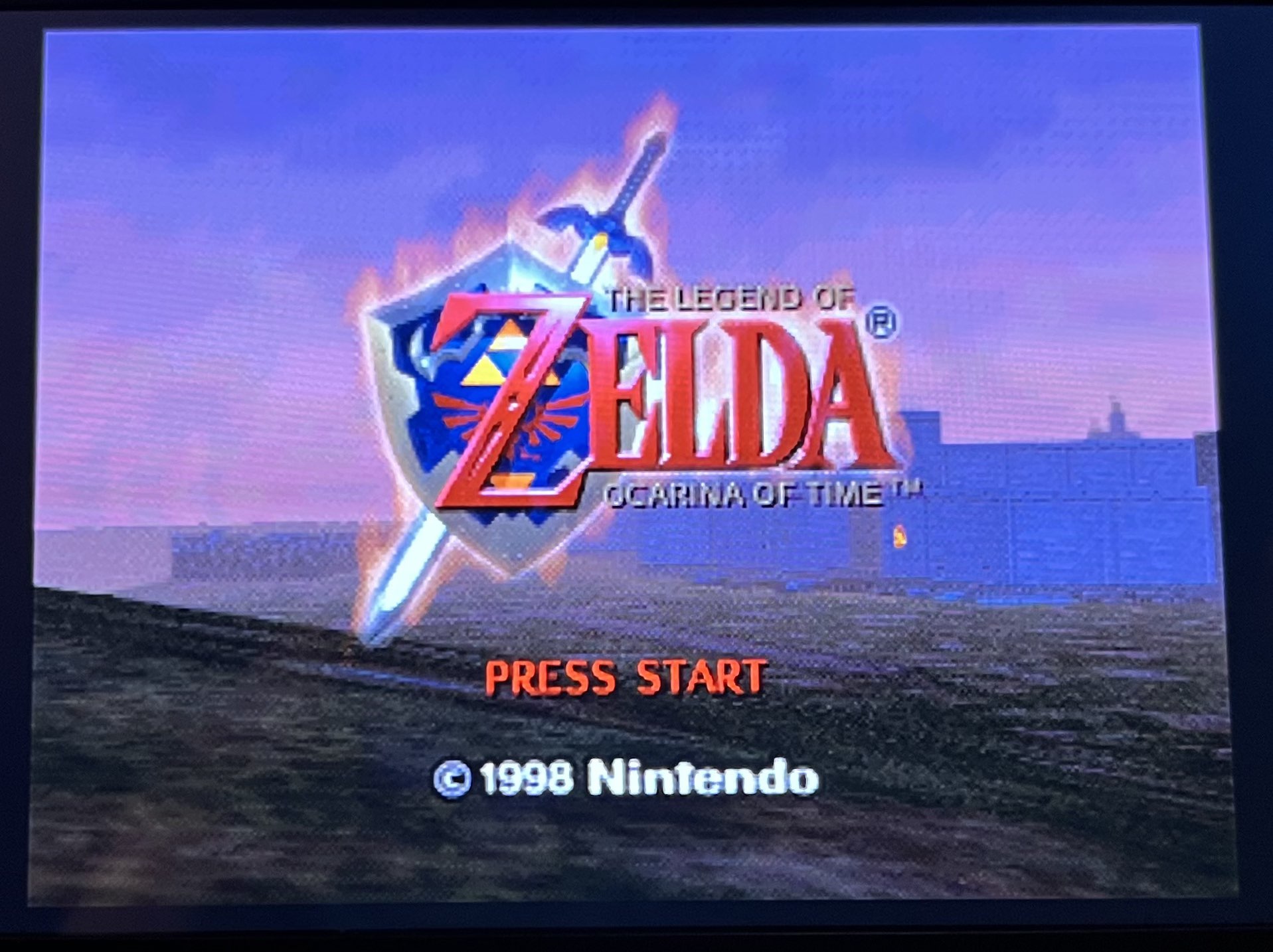
Another no anti aliasing patch
Stock
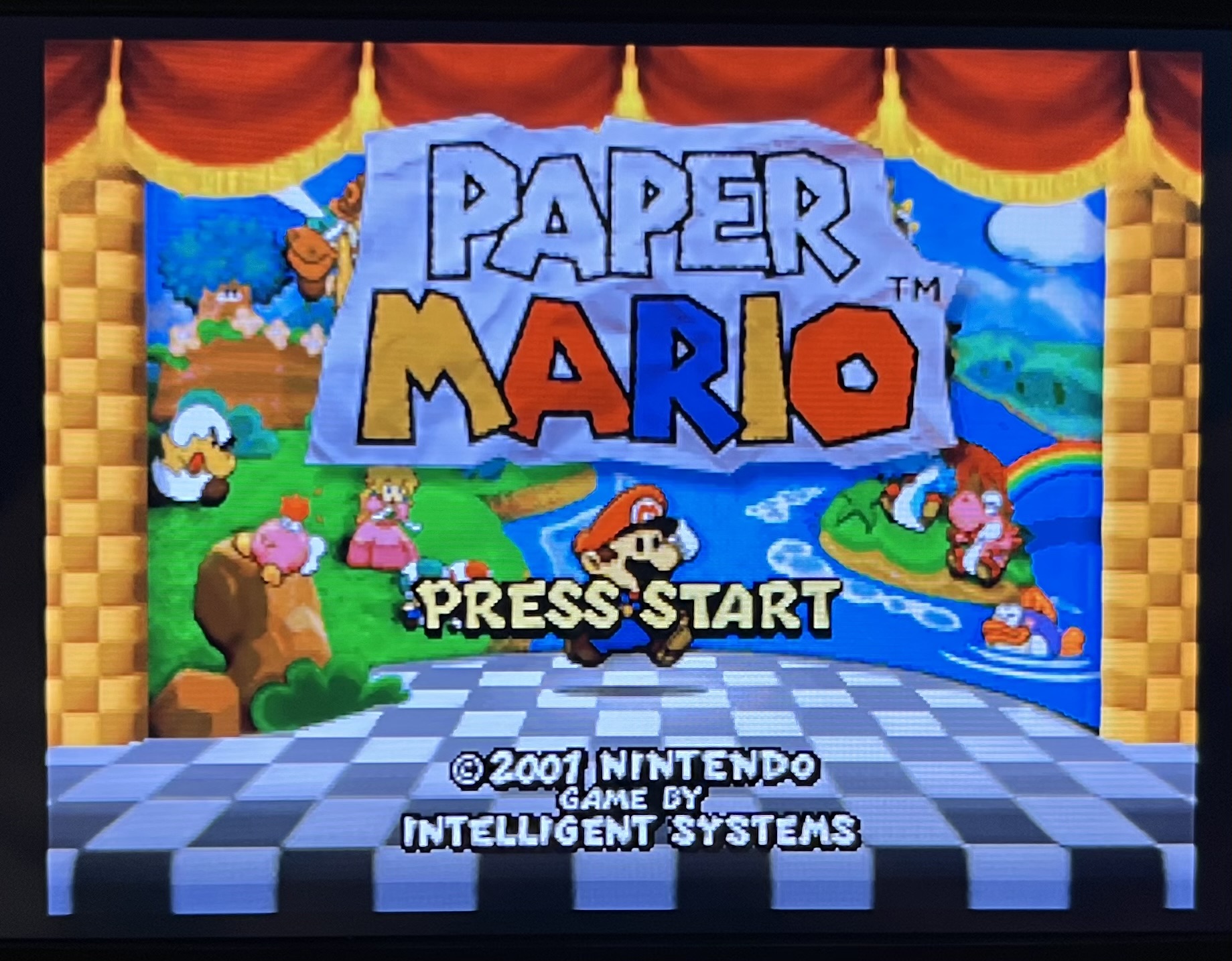
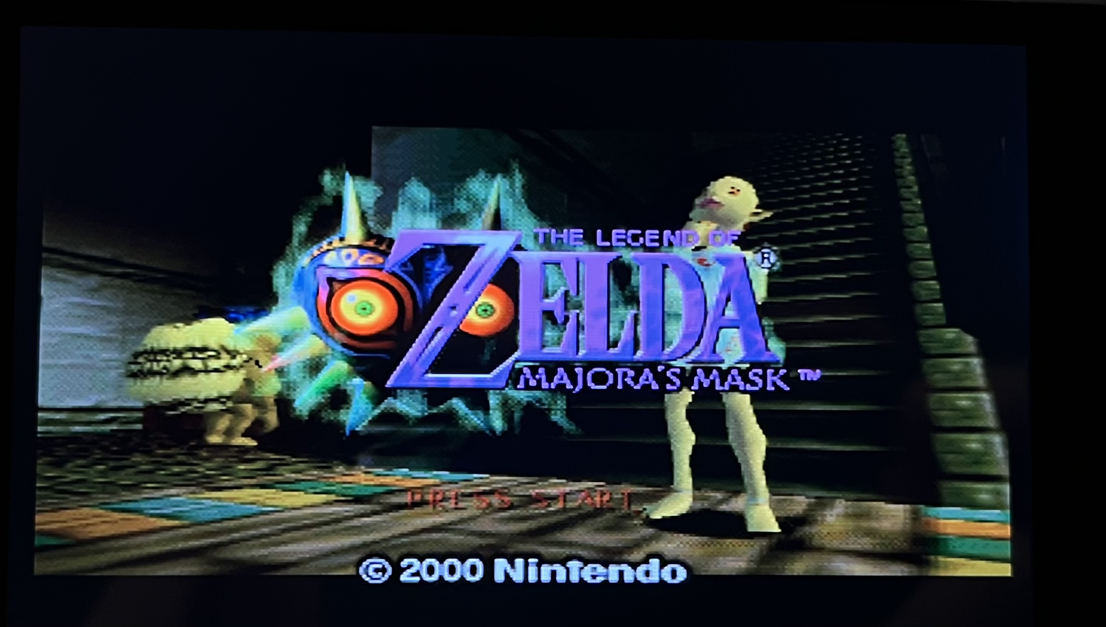
Stock
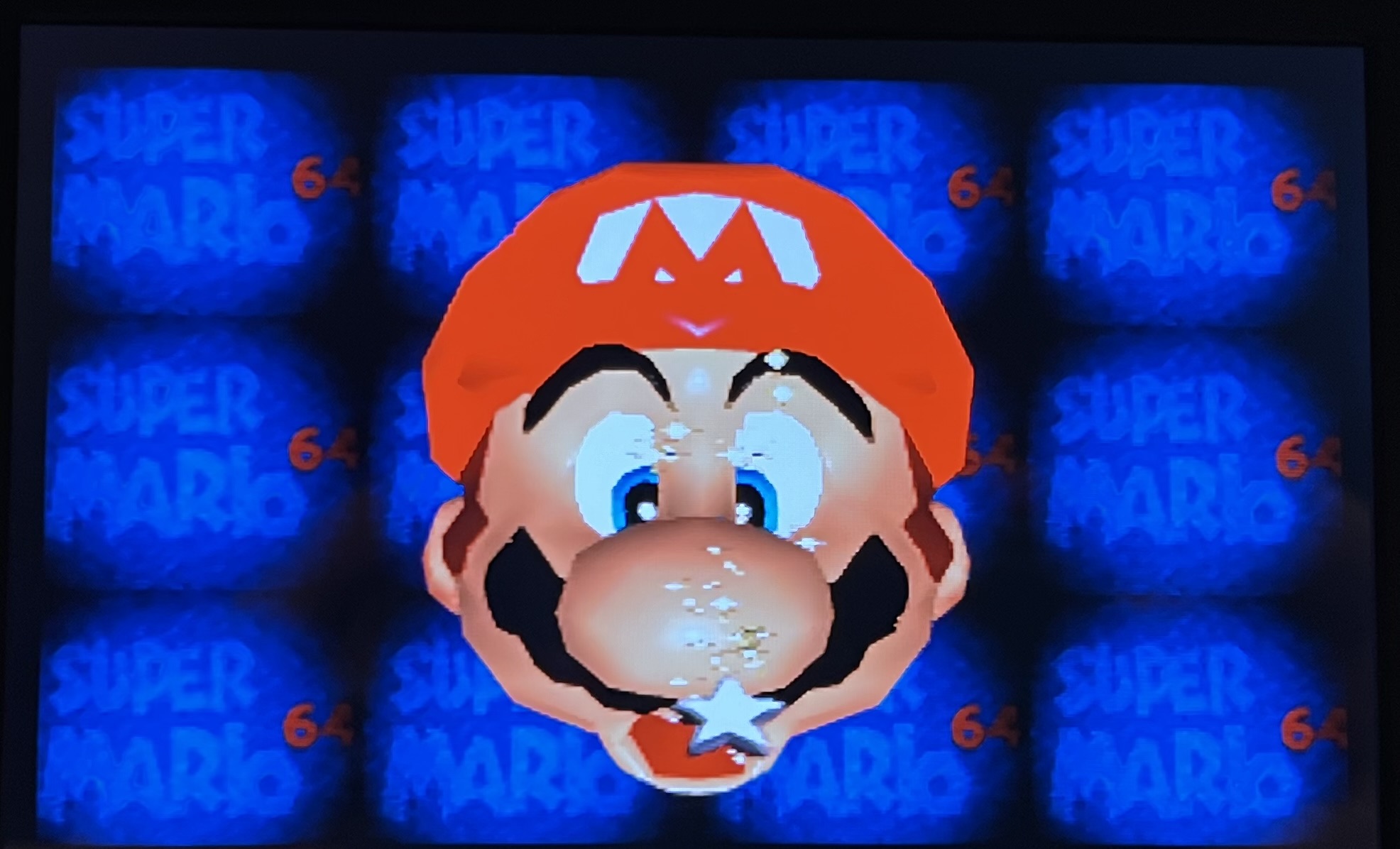
I swear these games looked better as a kid... these graphics haven't aged well lol.
Overall the Hispeedido looks pretty good just has a lack of OSD options.
Will look into N64 Advanced next to see if that has a better video clarity.
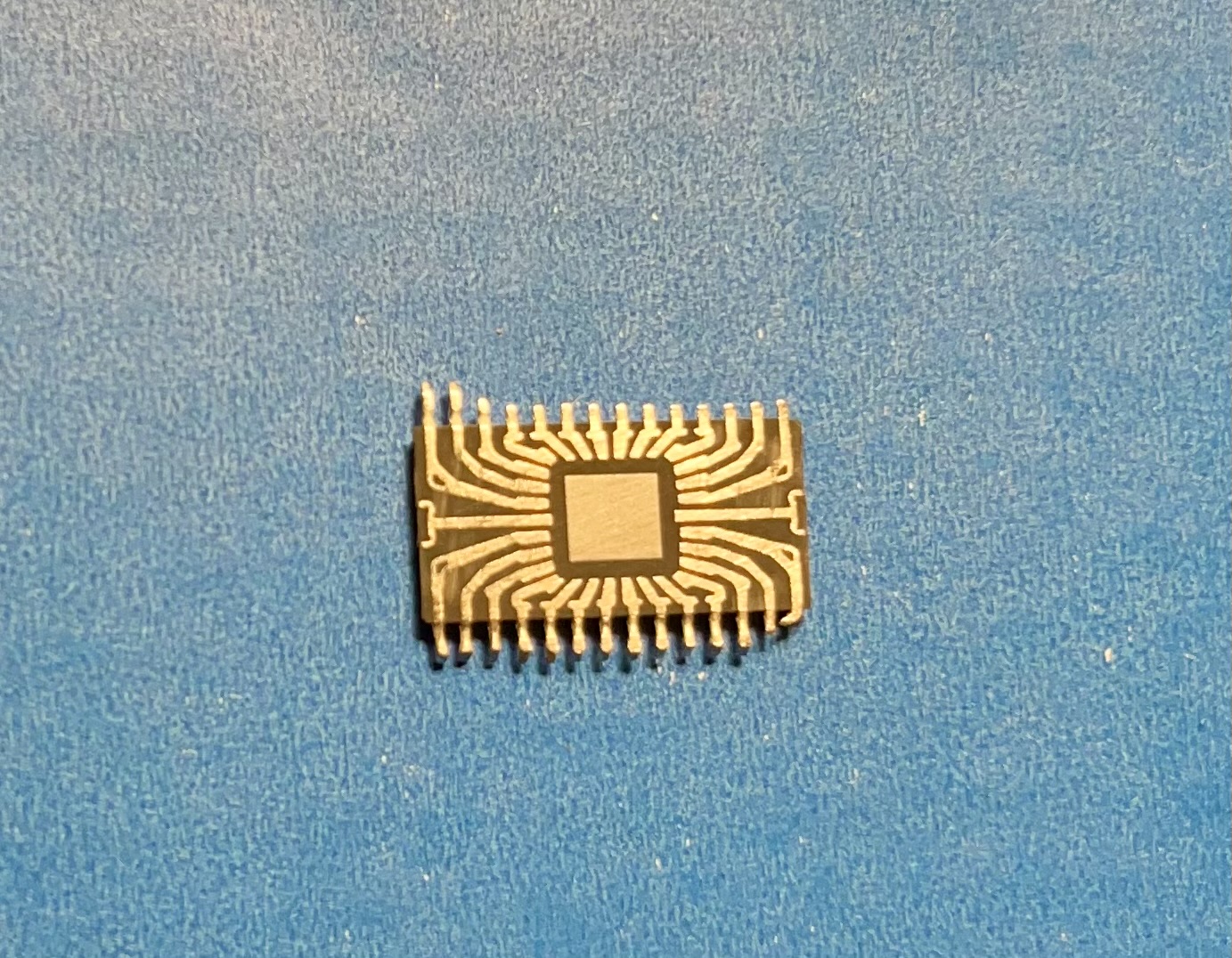
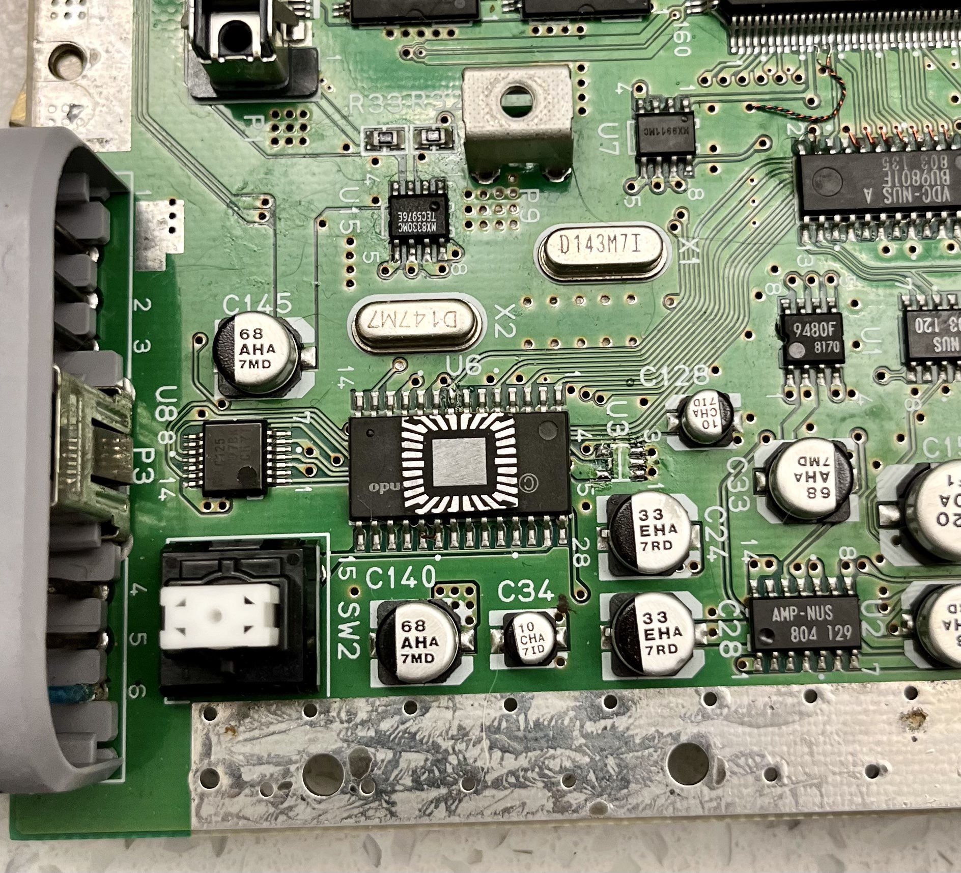
Another idea was doing a chip trim of the PIF. It makes it about half the size and the spacing of the leads are far enough apart to make it simple to solder in theory.
I've really enjoyed motherboard redesigns, a nice engineering puzzle for soothing the mind. So here's my take on the N64.
I definitely threw ground vias in an organized chaos at the end. I cross referenced this board with different revisions of the N64 as well as the compendium and seems to be okay.
I am replacing the through hole crystals with SMD crystals of the same value to see if that will work. Yveltal also gave the idea of replacing both MX clock generators (1 dual clock generator on later revisions) with programmable oscillators for a smaller footprint which I plan on testing in the future once I confirm functionality with this redesign first.
Still figuring out what to do about the video out but have tested a couple options.
The Pico DVI N64 project (https://github.com/kbeckmann/PicoDVI-N64) is super cool but doesn't look great as there are color banding issues. To be fair, it is more so a proof of concept as opposed to a final product. Don't have any pictures to show for this option since I won't be going this route.
Also there is the Hispeedido N64 Digital HDMI (https://www.aliexpress.com/i/3256805447859074.html) solution which is a great price and actually looks pretty good, just wish there was a scanline setting. Only draws 0.25w @ 3.3v! The circuit is simple, so would be easy to implement on board with the N64 core to have an all in one. I'm considering this option. It outputs a 720p image and I'm testing it on a 720p monitor in 4:3 mode. Here are some photos:
Stock
With no anti aliasing patch (using https://github.com/mrdemkin/N64noAAPatcher) which sharpens but makes dithering more apparent.
Another no anti aliasing patch
Stock
Stock
I swear these games looked better as a kid... these graphics haven't aged well lol.
Overall the Hispeedido looks pretty good just has a lack of OSD options.
Will look into N64 Advanced next to see if that has a better video clarity.
Another idea was doing a chip trim of the PIF. It makes it about half the size and the spacing of the leads are far enough apart to make it simple to solder in theory.
Last edited:
