Worklog Retro Lite CM5

StonedEdge

a.k.a. ClonedEdge
.
.
Joined
Nov 16, 2018
Messages
366
Likes
1,495
Location
Japan, Tokyo
Portables
2
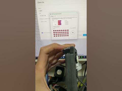
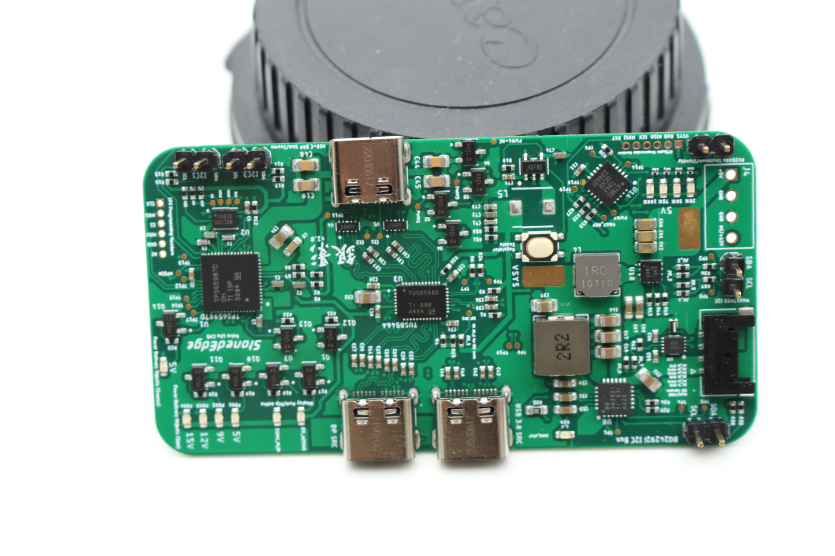
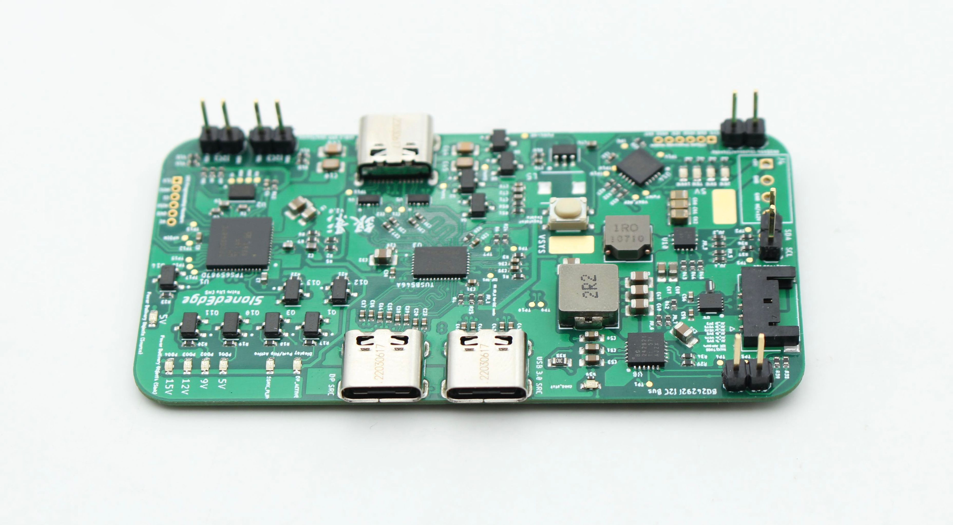
The components are finally all soldered onto my test board so I thought I'd share a photo - they look great! But do they work - that's the next adventure.

I'll get into testing the TPS65987D USB-C PD controller over the next few weeks & report back with any road blocks.

Right now, the test board has 4 LEDs to indicate the PD sink profiles & 1 for the PD source profile. The side with the bottom USB-C port is what will be on the final build and do all of the USB-C shenanigans you'd expect from any modern phone. Will definitely try out a few dongles soon! #donglelife

Meanwhile, we have switched over the controller to the RP2040 instead of the ATMEGA32u4 with our IMU and achieved basic air mouse functionality thanks to GinKage's work (the RP2040 is cheaper and just overall, better in most ways).

I haven't really thought of any retro games where this application works but it should be great for moonlight streaming modern PC games. Maybe light gun games (Time Crisis, Metroid Prime Hack) and other Wii games could benefit from this for sure.

1701687141349.png

385547323_373405375193873_3510570594894144036_n.jpg


Last edited:
Joined
Mar 2, 2023
Messages
8
Likes
1
I don't know if this would be pushing it, but have you considered using switch lite batteries and maybe screen? Might be too late for the screen part and the old battery is fine, I was just curious if it might make the whole process easier to source.
 

StonedEdge

a.k.a. ClonedEdge
.
.
Joined
Nov 16, 2018
Messages
366
Likes
1,495
Location
Japan, Tokyo
Portables
2
I don't know if this would be pushing it, but have you considered using switch lite batteries and maybe screen? Might be too late for the screen part and the old battery is fine, I was just curious if it might make the whole process easier to source.
Yeah, I’m already quite far into the design phase now and have been redoing the CAD work from scratch. A few people have asked if I can use an OLED or if I can use the switch screen. I think it could be possible, but I don’t think I can get the switch screen working as much as it would be great to use - I just don’t know how it works and not sure if there are any drivers for it available.

Speaking of design, I’ve managed to redo the whole thing to be injection moulded. It’s now a bit bigger in certain dimensions but it fits a switch lite fan now and a bigger battery (5500mAh). I’m now working on the trigger mechanisms which honestly is the most difficult part about designing these things.

7E41D398-6452-40EE-AC3B-A4BD867953A2.jpeg
 
Joined
Mar 2, 2023
Messages
8
Likes
1
Yeah, I’m already quite far into the design phase now and have been redoing the CAD work from scratch. A few people have asked if I can use an OLED or if I can use the switch screen. I think it could be possible, but I don’t think I can get the switch screen working as much as it would be great to use - I just don’t know how it works and not sure if there are any drivers for it available.

Speaking of design, I’ve managed to redo the whole thing to be injection moulded. It’s now a bit bigger in certain dimensions but it fits a switch lite fan now and a bigger battery (5500mAh). I’m now working on the trigger mechanisms which honestly is the most difficult part about designing these things.

View attachment 30979
That makes a lot of sense, there's a reason I haven't built anything like this yet, scarry and I don't know if my skill level matches and I don't want to waist the money. Honestly keep up the great work
 

StonedEdge

a.k.a. ClonedEdge
.
.
Joined
Nov 16, 2018
Messages
366
Likes
1,495
Location
Japan, Tokyo
Portables
2
Please excuse the messy desk, but we have a working Type-C DRP extcon now with PD sink/source profiles, a SuperSpeed mux for cable flip & Type-C Alt Mode. You can see I am using an active Type-C to HDMI dongle, but I’d like to try it out with other off the shelf docks eventually. The setup was really simple. You select the parameters in the GUI, generate a binary and then dump it with a Pico or any SPI flasher, really. The mux even works in basic GPIO mode - no need for any external I2C master to control it, although the option is there of course.

I had to force DisplayPort out of the Type-C port in the kernel device tree, as the carrier board already has a FUSB302 controller on it. I also set the rockchip,dp-lane-mux node to the correct mappings in order to get it to output DisplayPort. I realized at first the Type-C cable I was using also didn’t have physical pins for the SuperSpeed lanes… ‍:facepalm: Nothing a quick visit to Bic Camera wouldn’t fix, although those cables are a bit pricey.

Power Delivery PDOs are now also working. 15V from the Switch charger as intended:

093533AF-0C1D-49CC-BF45-047A1F631D09.jpeg


Thanks to GinKage for helping me with the kernel patches :D:P Here it is running on battery power - I’m yet to do any tests on battery life yet, but will definitely do some after Christmas is over.

8F95AC5F-7057-452A-B995-168298047E2E.jpeg
2710933B-972F-4C0E-8D4E-D0F8F26F4F29.jpeg


I should have the CAD work finalized in the next couple of days so I can run a test print. I also need to hit the order button for the RP2040/IMU controller boards this week too. I’ll probably take a break after Christmas and then be back to working on the carrier board in the new year!
 
Last edited:

StonedEdge

a.k.a. ClonedEdge
.
.
Joined
Nov 16, 2018
Messages
366
Likes
1,495
Location
Japan, Tokyo
Portables
2
The new Retro Lite CM5 shell design is "mostly done" so I thought I'd share what's changed vs. the CM4 - I think it's a good improvement over the previous design so I'm excited to share it!

1704432973451.png

1704433087649.png


The trigger design has been improved to support dual tact buttons and is now a 3 piece assembly instead of 6. Having the luxury of designing the shell for injection moulding/3D printing definitely allowed to simplify Dmcke5's old design which was a little bit complicated and designed for machining instead. The top trigger hinges also had a tendency to snap and didnt work so well when you pressed up too high due to little mechanical advantage. Hopefully a lighter tact switch and new design should help with that.

New design - 2 piece assembly
1704431364645.png


Old design - 4 piece rod/pivot assembly
1704431440414.png


Case thickness of the new model has increased by 30% - 19mm vs. the previous 14.5mm. The upside with the greater thickness is a much sturdier case for 3D printing (actually now a viable option to make this for hobbyists on the cheap, where the previous case was too flimsy to do well). Money is definitely tight for me at the moment so being able to 3D print a prototype shell and not have it snap due to being too thin is actually a nice plus.

1704431786300.png


The case should technically be injection mouldable if we ever go down the route of mass producing these, but I really have no way to verify that "it's ready" as I have never really gone down that path. We'll see if I can get someone to take a good look at it for review (feel free to have a look - I'll be uploading v1 to GitHub shortly). I did add some things like gussets to the side walls for extra strength and such, too.

1704432251211.png


1704431524764.png


Another plus is a bigger battery - 5000mAh instead of the previous 4000mAh. I also included a battery bracket to mount the pack. The previous design mounted the battery to the display, which I really wanted to avoid in this version as it can lead to backlight bleed if too much pressure is applied to it.

1704431692350.png


The switch lite fan is integrated, which is a much quieter fan than the old one and mounts to the rear. I still need to create a small breakout PCB for it as it won't reach the front PCB without a cable.

So...now that the CAD has been entirely re-done from scratch... what's next?

I've ordered two sets of the RP2040 controller PCBs and they are on there way! I'll populate all the components & we can get those working - a lot of the code is already done.

1704431973461.png


After that, it's time for me to return my attention to the main carrier board which I've neglected for a few months. Radxa still haven't finalized their CM5 design for manufacturing, so it makes it hard to order something with 100% certainty that nothing will change vs. the samples I have been given. GinKage is going to be working on getting the USB-C Type C DisplayPort/HDMI ports working as a Nintendo Switch would (i.e disabling the internal display when plugged in) as well as setting up our EmulationStation image to be used with Weston.

I've been drawing up a few concepts for the OSD as well. It would be relatively simple and allow the user to change the volume, brightness and CPU/GPU clocks from the GUI, as well as show things like battery level, FPS, and other metrics. Time will tell how hard it will be to implement - but we definitely want a way to toggle the gyroscope on and off as it will be annoying to have it on all the time. The text is obviously too small to legibly read too, but its just a first draft. Tweaks to be had, of course.

1704431900523.png


Well, that's all for now! See you next time.
 
Last edited:

Wrn_

.
Joined
Jan 13, 2023
Messages
14
Likes
27
The trigger design has been improved to support dual tact buttons and is now a 3 piece assembly instead of 6.
Would you be open to sharing that trigger/bumper design? its one of the things ive been struggling with most the modeling process.
 

StonedEdge

a.k.a. ClonedEdge
.
.
Joined
Nov 16, 2018
Messages
366
Likes
1,495
Location
Japan, Tokyo
Portables
2
Would you be open to sharing that trigger/bumper design? its one of the things ive been struggling with most the modeling process.
Yes, all will be open sourced eventually and on GitHub so you can see the details when I’ve finished the model. Just need to make a few more tweaks before it’s uploaded.
 

StonedEdge

a.k.a. ClonedEdge
.
.
Joined
Nov 16, 2018
Messages
366
Likes
1,495
Location
Japan, Tokyo
Portables
2
Would you be open to sharing that trigger/bumper design? its one of the things ive been struggling with most the modeling process.

STL files for the enclosure and buttons have now been uploaded here (keep in mind this is a v1.0 & I may still make some tweaks here & there).
 
Last edited:

StonedEdge

a.k.a. ClonedEdge
.
.
Joined
Nov 16, 2018
Messages
366
Likes
1,495
Location
Japan, Tokyo
Portables
2
I made a bit of a botch on the USB 3.0 input, nothing that a bit of jumper wire couldn't fix up.
I didn't bother testing the speeds yet since I doubt they will reach the theoretical max of 5 Gbps with the butchered wiring (the RK3588s only supports USB 3.1 Gen 1 speeds & not Gen 2). But I'm glad I now have a fully functional USB-C port that will do USB 3.0 speeds, DP video out & OTG support. Nice.

1707282977874.png


Here's proof that it is recognizing my mass storage device over USB 3.0. This is in 2 lane DP/USB 3.0 mode.

Code:
stonededge@rock-5-cmio:~$ lsusb -t
/:  Bus 06.Port 1: Dev 1, Class=root_hub, Driver=xhci-hcd/1p, 5000M
    |__ Port 1: Dev 3, If 0, Class=Hub, Driver=hub/4p, 5000M
        |__ Port 3: Dev 4, If 0, Class=Mass Storage, Driver=usb-storage, 5000M
Meanwhile, GinKage has been working hard on the programming side for the controller - we have a working RP2040 gamepad now with all the correct mappings. Exciting :D


The case has been re-strengthened to add reinforcement to the side walls, as well as thickening up certain sections so it can be better suited for 3D printing.
I'm about to make an order with JLCPCB MJF nylon, so I'll be sure to post how it looks when it arrives.

1707283578510.png


The PCB carrier board is also done, but I am waiting until fab houses are back from LNY as most places are shut until Feb 18th.

Drawing closer to a finished prototype I think! April target is well within reach.
 
Last edited:
Joined
Feb 20, 2024
Messages
1
Likes
1
Hi, first of all awesome work!! I always wished to be as brilliant as you to do something like this on my own. Keep going, I hope I will be able to build one when it's finished.

To your housing design, I have one question. Why do you copy the switch thumb stick positioning? At the release of the switch I've read a lot about why Nintendo is doing this async positioning, and yes the answer is easy. It's because of the joycons can be used separated from the console. So the thumb stick will always be on the right side.
But there were also a lot of negative comments about that this positioning is a pain in the ass for players with big hands.
So do you had special intentions why using this layout? Instead of using a symmetric positioning?

Thanks Max
 

StonedEdge

a.k.a. ClonedEdge
.
.
Joined
Nov 16, 2018
Messages
366
Likes
1,495
Location
Japan, Tokyo
Portables
2
Hi, first of all awesome work!! I always wished to be as brilliant as you to do something like this on my own. Keep going, I hope I will be able to build one when it's finished.

To your housing design, I have one question. Why do you copy the switch thumb stick positioning? At the release of the switch I've read a lot about why Nintendo is doing this async positioning, and yes the answer is easy. It's because of the joycons can be used separated from the console. So the thumb stick will always be on the right side.
But there were also a lot of negative comments about that this positioning is a pain in the ass for players with big hands.
So do you had special intentions why using this layout? Instead of using a symmetric positioning?

Thanks Max
I guess it was just a personal preference for me. For stick input “heavy” games like PS2 or GameCube, I think it makes sense to have the face buttons equal to the height of the main input. But I will release a CAD model with the DPAD up top as well, as this seems to get requested pretty frequently and it’s not very difficult to change. Hopefully that will keep everyone happy :)
 

StonedEdge

a.k.a. ClonedEdge
.
.
Joined
Nov 16, 2018
Messages
366
Likes
1,495
Location
Japan, Tokyo
Portables
2
Small update time!
New MJF nylon case arrived from JLCPCB. It feels great and is high quality. The rear was slightly warped but not too bad, definitely usable. It cost about $45 for all the CAD parts, including buttons. Not bad at all. :awesome:

429474253_3639416142971692_1325925931006371747_n.jpg


429638517_1076441940283643_940643650066143011_n.jpg


429474837_383073868010581_8807325921473721861_n.jpg


The final v1.0 PCB design is completed and I have uploaded it (the EAGLE CAD files) as well as the gerber files to GitHub for those interested in having a look/making improvements. I may also try recreating this in KiCad since I want to move away from EAGLE for my next project - it's being discontinued after all.

Keep in mind I haven't tested any of this - there may be bugs! I should have two prototypes in hand by the end of this month from JLCPCB so we'll know more soon. I am hopeful since we've already tested most of the hardware out anyway. And hey, jumper wire exists for a reason. But god, prototyping is expensive...

Exciting times! I just heard from GinKage that Panthor has just landed in drm-misc-next, so we should have some good graphics drivers to play around with soon.
It's no PanVk, though, but hopefully, we will get it all integrated soon and get rid of the desktop shell, since it's not ideal for a handheld system.

We haven't decided whether our image will use ES-DE or regular old ES yet for the front end.
I guess the user can do whatever they please, it is open source after all. :D

429617239_927852648630428_2445275895465794545_n.jpg


Oh and as a spoiler, here is our working gyrometer in Breath of the Wild with the RP2040 & powering up the device from a battery using the BQ24292i, TPS61235 & the ATtiny84, which we programmed in the PlatformIO IDE.


Next update hopefully will be booting the RK3588s CM5 SoM from the new carrier board.

tenor.gif
 
Last edited:

StonedEdge

a.k.a. ClonedEdge
.
.
Joined
Nov 16, 2018
Messages
366
Likes
1,495
Location
Japan, Tokyo
Portables
2
Think I’ve finally reached a point where I’m happy with the trigger design. It’s no analog trigger but the dual tact saves the day ;)


StonedEdge

a.k.a. ClonedEdge
.
.
Joined
Nov 16, 2018
Messages
366
Likes
1,495
Location
Japan, Tokyo
Portables
2
I had a lot of issues with JLCPCBA and their engineers mixing up my land patterns with their stock LCSC library, which delayed ordering the boards by at least a couple of days. Safe to say it was a very frustrating experience, but to give them credit, they did solve the issue for me in the end with enough pestering to the chat agents.

The boards are in production! I should have them by next weekend in hand & delivered. We've already put together an initial device tree here. For those who don't know, a device tree in simple terms explains the hardware setup (including GPIO mappings and various configurations for the specific hardware).

Some parts I couldn't source with JLCPCB as they have minimum assembly quantities, so I will still need to solder two components by hand. Not a huge deal though.

1710816016125.png


GinKage has also been playing around with relatively fresh Linux kernels (6.1.57, from Rockchip sources circa 2024-03-01) running with Panfork drivers (bit old... but they work) via HDMI. Unfortunately, the DSI drivers still don't work with this kernel (the DSI driver's probe method seems to never get called, so VOP just keeps looping in EPROBE_DEFER...), so it looks like we may revert to 5.10 BSP just to get something working for now to test with.

1710816250386.png
 
Last edited:

StonedEdge

a.k.a. ClonedEdge
.
.
Joined
Nov 16, 2018
Messages
366
Likes
1,495
Location
Japan, Tokyo
Portables
2
CM5 rev 1 carrier board PCBs are here! Hooray. :D

I will let everyone know if any magic smoke appears this weekend.

.jpg
 

StonedEdge

a.k.a. ClonedEdge
.
.
Joined
Nov 16, 2018
Messages
366
Likes
1,495
Location
Japan, Tokyo
Portables
2
Quick update. Rev 1 won’t be the final revision (shock horror). The third connector was completely upside down which means nothing on it works. I’ve removed it for testing at the moment and will hand it over to GinKage to play with whilst I’m on vacation for the next week.

For now, things that don’t work because of the borked connector:

- USB 3.0
- DisplayPort
- USB 2.0 host ports (PCIe/USB-C)
- Fan PWM control
- Hopefully nothing else

Things that are working! Yay:
- General boot up
- SDIO
- WiFi
- Bluetooth
- Gamepad
- Audio
- Touchscreen
- MIPI (with a bodge)
- USB-C charging
- RTC
- Gyro

So, it’s on to Revision 1.1 unfortunately which is a bit upsetting & a hit to the wallet that I would’ve not liked to endure. I guess I can’t beat myself up too much. Anyway, here’s some pictures of the working unit so far.

8D9EAD23-BC96-45F0-87AB-849A16C514FB.jpeg
EA718F09-707F-4891-801E-06ECB7AC91F1.jpeg
90EA1571-7037-4ADC-B3D1-BE52E0B24C0F.jpeg
 
Top