Just the D pad on the GC+ is good. If you get continuity from there to the player 1 data line on the Wii, then your controller data wiring is fine.
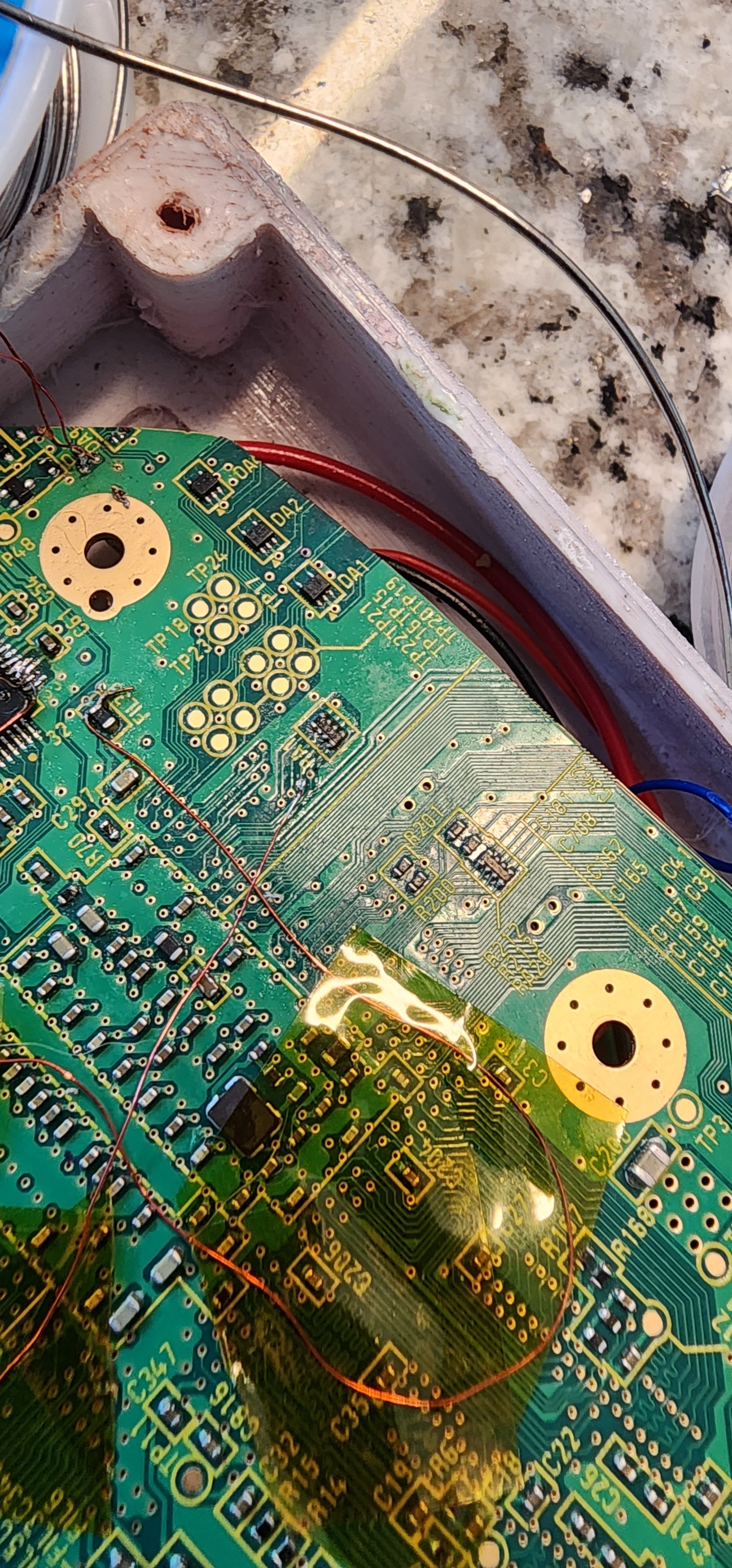
Although I must recommend that you shorten the amount of exposed wire in your build. There are many instances of exposed wires being long enough to short against nearby ground and voltage pins, which could damage your components
Ok, I am seeing continuity between the GC+ and the Wii. I will try to snap a picture later today when I have someone here to take the picture while use the multimeter. I'll start cleaning up some of that exposed wire in places. I don't think the controller is grounding out but better be safe than sorry. Could it just be the PCB board? Is there a way to verify that the individual buttons and joy cons on the pcb board are actually sending signal?
Update:
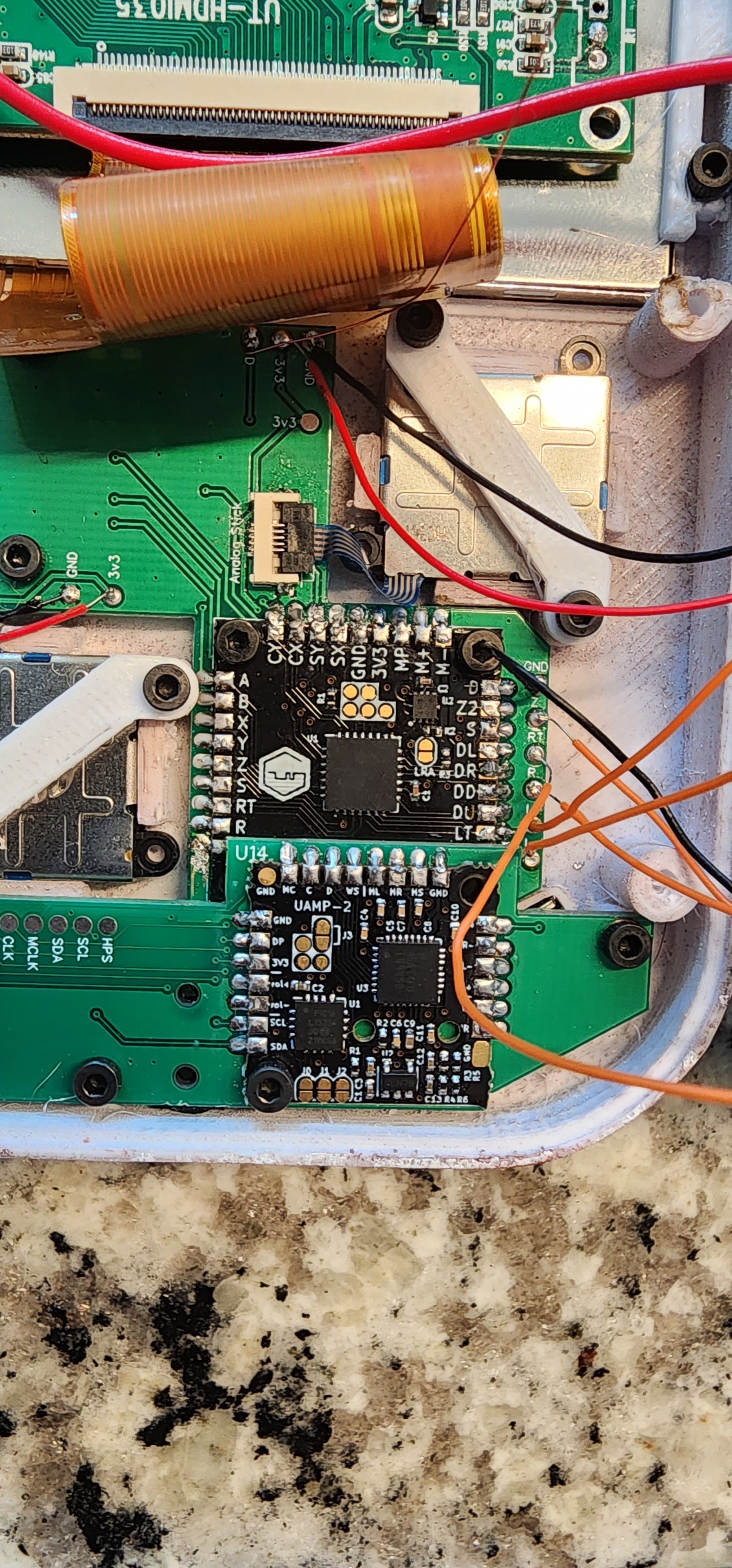
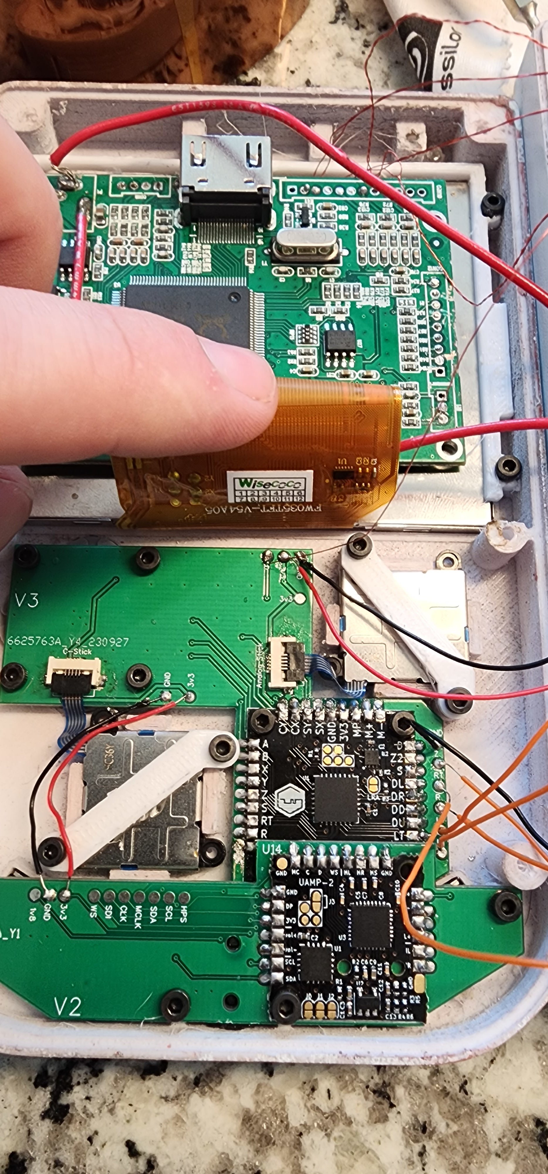
I swapped out the PCB board and resoldered everything with no luck. I get continuity to the Wii vias, I get 3.3v to the board but no luck. Is there a way to check if this guy on the Wii is damaged somehow or not getting singnal correctly?
Further edit:
Still nothing. I wiped everything down with IA, still see continuity to the Wii and I'm getting 3.3v to the PCB but nothing. No buttons work and no joystick input. I'm wondering if the issue lies somewhere with the Wii. Everything else looks solid I just can't seem to figure out what's wrong. Would the data line that goes to the Wii need to be shielded? I've not seen anyone do it but would this magnet wire need to be wrapped like the VGA wires? I'm just trying to think of anything else that could be causing an issue there.