Release Fujiflex (GCVideo DVI flex PCB)

YveltalGriffin

First Wii U Trimmer
.
Joined
Jun 7, 2016
Messages
306
Likes
1,143
Location
South Florida
Portables
5
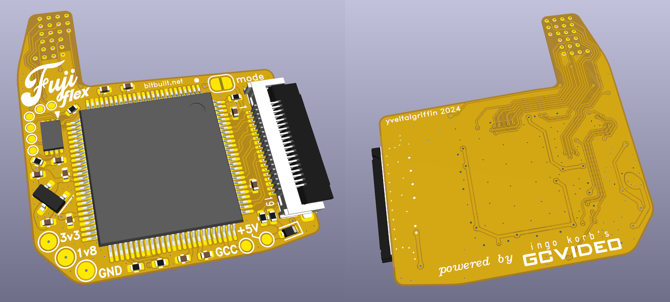
I recently released fujiflex, a GCVideo DVI flex PCB for 4-layer Wii motherboards. It is permissively licensed under the Solderpad Hardware License v2.1! GITHUB LINK

fujiflex.png


Features:
  • Compact 28 x 30mm 2-layer flex PCB (requires KiCAD 8.0 or later)
  • ~$10 BOM cost
  • Powered from 3.3V and 1.8V (1.2V generated from 1.8V for power savings)
  • 19-pin Molex 5052781933 / 5052781970 ZIF for HDMI output
  • Wii SDA and SCL testpoints
  • MODE solder jumper
  • Powered by Ingo Korb's GCVideo DVI
You can connect fujiflex to any HDMI driver board with a 19-pin FFC. You just need to solder a 19-pin ZIF to the driver board in place of the HDMI connector. See supertazon's G-Boy for reference. The GitHub repo has more details about assembly, programming, and installation.

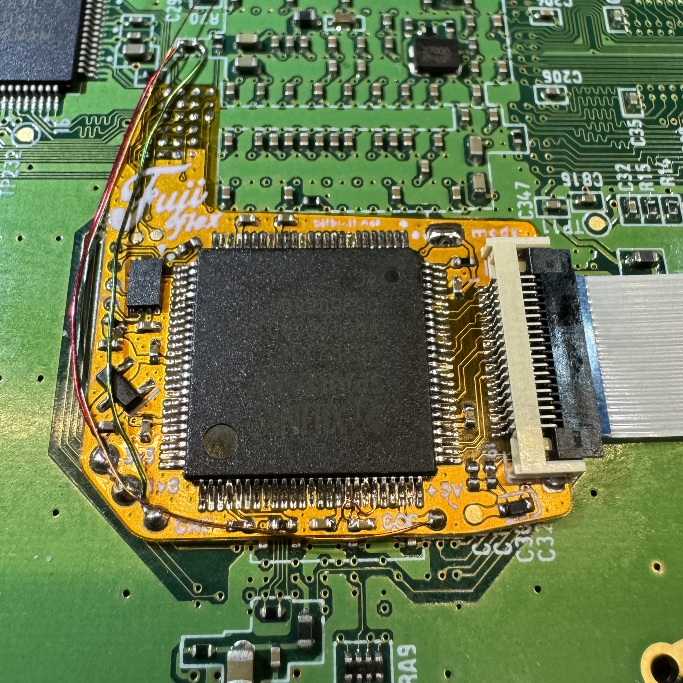
Huge thanks to @loopj for testing the boards and helping with the assembly/installation documentation! Here's a pic of his successful install:

install.jpg
 
Joined
Jan 26, 2024
Messages
38
Likes
54
Well, I was planning to do a vga switcher on my current g-boy project then saw this. I got everything ordered to make a few of them, so if the first one works out and I don't need the others, I'll offer them at cost + shipping for anyone who would like to do this mod. Thanks for all your hard work on this @YveltalGriffin!
 
Joined
Jan 26, 2024
Messages
38
Likes
54
Fuji Flex, assemble!

1711839226907.png


For some reason my order from Mouser is missing the 100k ohm resister so I subbed it for an 0802, although I'm not confident with the connection on it so I'm going to end up replacing them with the proper 0402 ones once I get them in. Working on programming them now.
 
Joined
Jan 26, 2024
Messages
38
Likes
54
Alright, so what do you do when the only unix based system in your house is a steam deck? Well....

1712029035754.png

1712029049050.png

1712029624616.png


It took a little bit of trickery to get flashrom installed due to the write protections put in place by "Steam OS" but I finally got two chips programmed! Tomorrow will be test day hopefully!

Just a few things I learned from programming these chips in case anyone else wants to try and struggles like I did:

- I tried flashing with a RaspberryPi Pico, EZP2023+, and a CH341A. I would by far recommend using the CH341A on a unix based system to flash the chip, it just works. With the Pico + Serprog, I couldn't get flashrom to play nice with it. For the EZP2023+, I could not get it to detect the chip no matter what I did.

-The system I used to install is running Arch Linux, but flashrom supports multiple flavors of Linux. Just be prepared to do a lot of googling to make sure you get the right packages installed.
 
Joined
Jan 26, 2024
Messages
38
Likes
54
Well, I got it installed but I'm running into an issue now, so hoping someone here can tell me what I'm maybe doing wrong. Whenever I boot the Wii, it powers on and the screen will flash blue and say "HDMI" in the top left, but constantly power cycle and get no video from the Wii. I did test the board prior to this install and it was working with composite. I also ended up tearing off the 5v pad by accident and soldered the 5v wire to the bridge rectifier directly instead. I checked continuity between the solder joints and the FPGA and everything seems good. Also checked continuity from the FPGA to the FFC connector, where that looked good too.

I originally had "mode" bridged but then remembered that was for forcing VGA and desoldered that, but same issue.

The screen is connected via the jack pins to 5v and ground on the PMS. Also, I did check resistances on that 100k ohm resistor and it checked out on all the pins it's connected to, so I didn't bother replacing it. Any thoughts?


In these pictures you'll also notice that ground appears to be connected to 3v3. It is actually just floating and I noticed it as I was posting this and resoldered it to the other side of that cap. Now it turns on to a blue screen and the wii immediately shuts off.
 
Last edited:
Joined
Oct 28, 2023
Messages
57
Likes
12
Well, I got it installed but I'm running into an issue now, so hoping someone here can tell me what I'm maybe doing wrong. Whenever I boot the Wii, it powers on and the screen will flash blue and say "HDMI" in the top left, but constantly power cycle and get no video from the Wii. I did test the board prior to this install and it was working with composite. I also ended up tearing off the 5v pad by accident and soldered the 5v wire to the bridge rectifier directly instead. I checked continuity between the solder joints and the FPGA and everything seems good. Also checked continuity from the FPGA to the FFC connector, where that looked good too.

I originally had "mode" bridged but then remembered that was for forcing VGA and desoldered that, but same issue.

The screen is connected via the jack pins to 5v and ground on the PMS. Also, I did check resistances on that 100k ohm resistor and it checked out on all the pins it's connected to, so I didn't bother replacing it. Any thoughts?


In these pictures you'll also notice that ground appears to be connected to 3v3. It is actually just floating and I noticed it as I was posting this and resoldered it to the other side of that cap. Now it turns on to a blue screen and the wii immediately shuts off.
Hello, I would like to ask if you have done it well, what programmer to use?
 
Joined
Jan 26, 2024
Messages
38
Likes
54
+1 on a cheapo CH341A-based device, I use
Heads up that flashrom works on linux, windows, and macOS. I use it on macOS.
Good point. I should have said that it's best used on Unix based systems. I looked into running it on windows and a lot of guides just said "don't bother".
 
Top