- Joined
- Aug 21, 2022
- Messages
- 5
- Likes
- 3
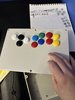
Hey! I am doing a very simple project to familiarize myself with the GC+2 board and microelectronic soldering projects in general. I'm just going to be taking a custom Hitbox style arcade controller I have and mapping it to the GC+ inputs so that my Hitbox can be used as a controller for a GameCube. I use a Hitbox when speedrunning certain Game Boy games with lots of menuing and button mashing as I find it more precise and easier on my hands than a traditional controller, so making my hitbox plug-and-play with a GameCube would be useful to me when running these games on console.
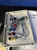
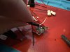
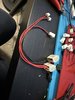
There's really not much to the first draft of this project - the only thing I am doing here is attaching buttons to a circuit. The only vaguely "complex" part of this is that I'll be making Y-cables for all my buttons, so that they can simultaneously be plugged into my existing PC/PS3 control board as well as the GC+2. I will only ever use one of these interfaces at a time, but that way I won't have to unplug and replug a bunch of buttons every time I switch from PC to console. So really, all I'm doing is splicing a bunch of wire with some lever nuts, and soldering on female 2-pin connector wire whips to the GC+2.
I am doing this project as kind of a practice run / prep for a future project. Eventually, I will be creating a Game Boy Player controller that recreates the button-feel and tactile sensations of the GBA SP D-Pad and face buttons, while being housed in a controller that is actually comfortable to hold for extended periods. This project is just to familiarize myself with the chip, and to brush up on my soldering a little. Once I start that project in earnest it will be its own (much more substantial) thread.
That said, if this project goes well, I may also take this concept itself to the next level. If this works, then I'd like to design a PCB to make using a custom Hitbox with a GameCube much easier. This would give me practice designing PCBs, which I will also need to learn. The board would simply have some interconnects on it (to solder a GC+2 board in place) and traces leading to a bunch of female 2-pin leads that match the connector used on most fight stick button cables. As far as I know, this doesn't exist yet. But before I go and design / make a PCB for that extremely specific purpose, let's just try soldering wires to the GC+2 and see if I know anything about what I'm doing at all right now.
I should get the GC+2 board next week sometime; in the meantime I have ordered a bunch of Baby's First Electronics Supplies to start me off. I've soldered in school / work settings before but never had my own equipment. Should be fun, I hope?
Wait, but this isn't a portable or console mod at all! Why are you posting here?
IDK, y'all seem cool and you all have a bunch of extremely relevant information here on custom button pads and housings, which is all a controller really is. Plus the GC+2 came from y'all folks, right? This is the closest community I can find that relates to the kind of projects I'm about to try to do. And also someday I want to do some GBA modding and maybe even console portabilizing.