Question just operate a 5v screen with 3.3v

Joined
Dec 29, 2021
Messages
64
Likes
10
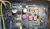
hello I currently have a screen card that works with a minimum voltage of 5v. So I had a question. is it possible to modify the board so that the screen can work with a lower voltage. I've never had to deal with this type of problem and I'm afraid of breaking my screen....
 
Joined
Dec 29, 2021
Messages
64
Likes
10
yes, I have already seen this guide. I think I found the regulators?!? but I don't know what to do anymore.
the first on the left of the image = 5v
the second =3.90v
the third = 3.33v
the fourth = 3.90v
 

Attachments

Stitches

2 and a Half Dollarydoos
Staff member
.
.
Joined
Feb 5, 2017
Messages
3,848
Likes
3,026
Location
Banana Bender Land, Australia
Portables
6
Supplying 3.3v to the 3.3v inductor *should* work
 
Joined
Dec 29, 2021
Messages
64
Likes
10
so I connect my 3.3v wire to the 3.3v output of the inductor?
should I remove the inductor to test if it works? can my screen die?
 

Stitches

2 and a Half Dollarydoos
Staff member
.
.
Joined
Feb 5, 2017
Messages
3,848
Likes
3,026
Location
Banana Bender Land, Australia
Portables
6
A mistake could kill the screen, yes. Removing the inductor isn't a bad idea, but you should first test to be sure that 3.3v input is enough to run the screen. If it works as expected, then you can remove the inductor
 
Joined
Dec 29, 2021
Messages
64
Likes
10
then... it works, the screen lights up but the charge and discharge module turns off and no longer powers anything. (he goes to safety I think)
 
Joined
Dec 29, 2021
Messages
64
Likes
10
knowing that I have kept everything, I am therefore not unsoldering anything.
 

Stitches

2 and a Half Dollarydoos
Staff member
.
.
Joined
Feb 5, 2017
Messages
3,848
Likes
3,026
Location
Banana Bender Land, Australia
Portables
6
Did you disconnect the 5v wire when you added the 3.3v wire?
 
Joined
Dec 29, 2021
Messages
64
Likes
10
I put my 3.3v wire at the point drawn in red and I connected my gnd wire to a gnd location on the board. I didn't change anything apart from that.
 

Attachments

JMCD

.
Joined
Feb 18, 2024
Messages
45
Likes
33
Location
UK
I put my 3.3v wire at the point drawn in red and I connected my gnd wire to a gnd location on the board. I didn't change anything apart from that.
I think that might be the input pin of that regulator not the output? Is it a 1117?
 

JMCD

.
Joined
Feb 18, 2024
Messages
45
Likes
33
Location
UK
Is it a fixed regulator or adjustable, fixed normally state voltage on them?
 
Last edited:

Xyzven

.
Joined
Jul 29, 2023
Messages
39
Likes
12
Not sure if this is a good answer but if you are using the PMS-Lite or PMS-2, you do know they have 5V regulated lines out right? You COULD try to use that line (provided you check it with the multi-meter). No guarantees it will be able to supply enough amperage though so YMMV.
 
Top