Jaredude
.
- Joined
- Sep 6, 2018
- Messages
- 4
- Likes
- 8
This project started as a wii micro, I had seen the MachoNacho GCNano video a while ago and I found this site, I did a little looking around but was too intimidated to start anything.
Someone posted the video later in my local smash bros melee discord and asked if it would be possible to make a melee themed wii case redesign.
I thought this sounded like a fun project so I took another look at what I would need to do it and decided to give it a shot.
My plan was to try a simple wii trim and make something like Jefflongo's wii micro, then paint it up to be themed around the local weekly melee tournament. (https://twitter.com/adamsmashseries)
I ordered a PSU-Plus from CrazyGadget (thanks!) and traded an old CRT I wasn't using for a family edition wii.
At the start of this project I wasn't comfortable with soldering on the motherboard so I wanted to do as little of that as possible and keeping the USB and AV out made it much easier.
Size wasn't as much of an issue on this project as it would be for a portable, so the extra room needed wasn't a problem.
While I was waiting for the PSU-Plus to arrive I took my first shot at making an [ASS] theme for RVLoader.
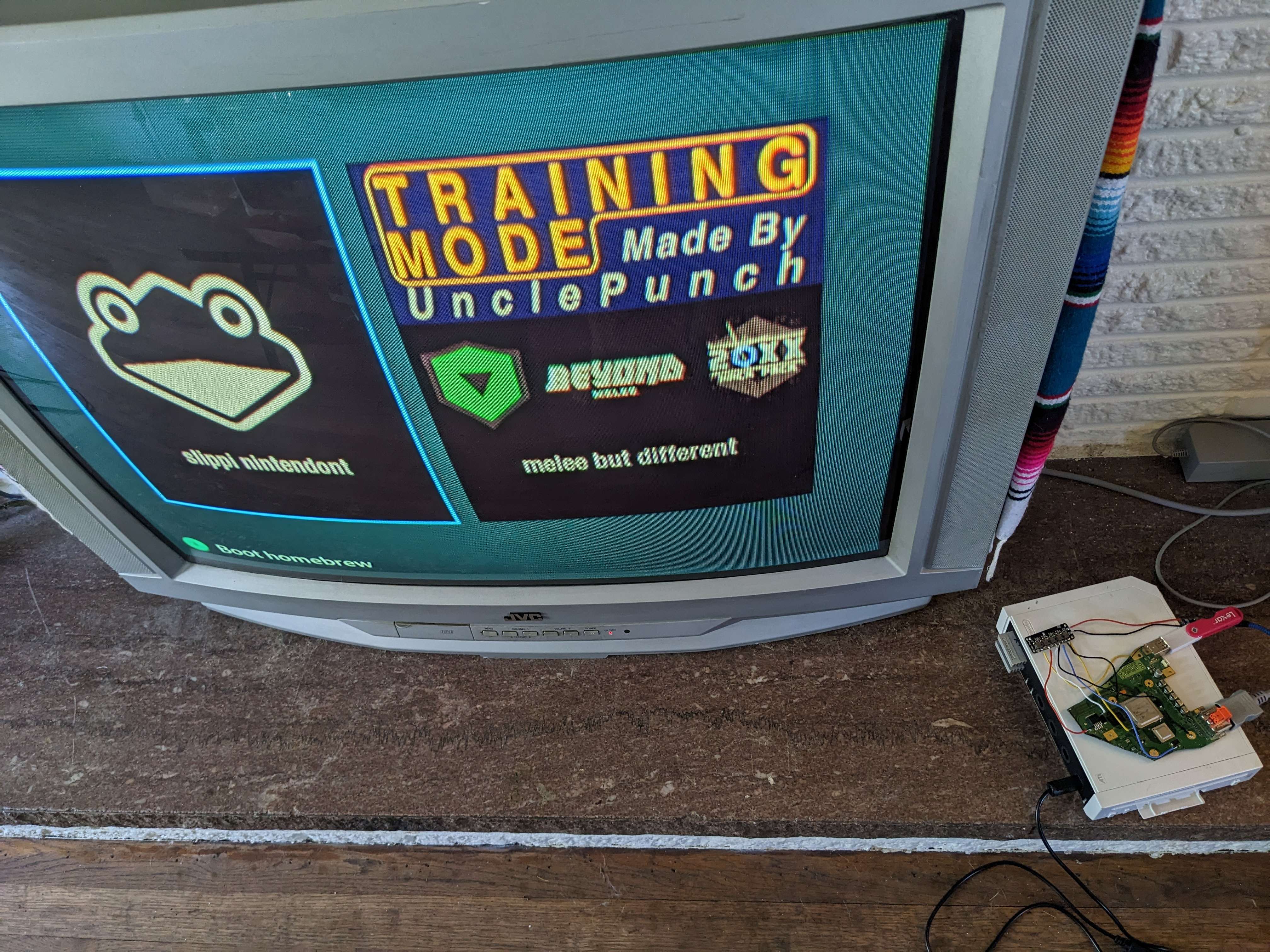
This thing is only ever going to play melee, so I changed the homebrew menu to only have room for two large choices to pick between
Slippi nintendont is a homebrew for playing competitive melee, then I would have regular nintendont as the second option so you could play melee romhacks or UnclePunch's Training Mode.
(I forgot to take a picture of the theme before I trimmed the wii )
The PSU-Plus arrived pretty quickly, and after a lot of double checking my trim wouldn't cut anything important I went for it.
The trimming was thankfully a lot less difficult than I expected and I had what I thought looked like a pretty good trim.
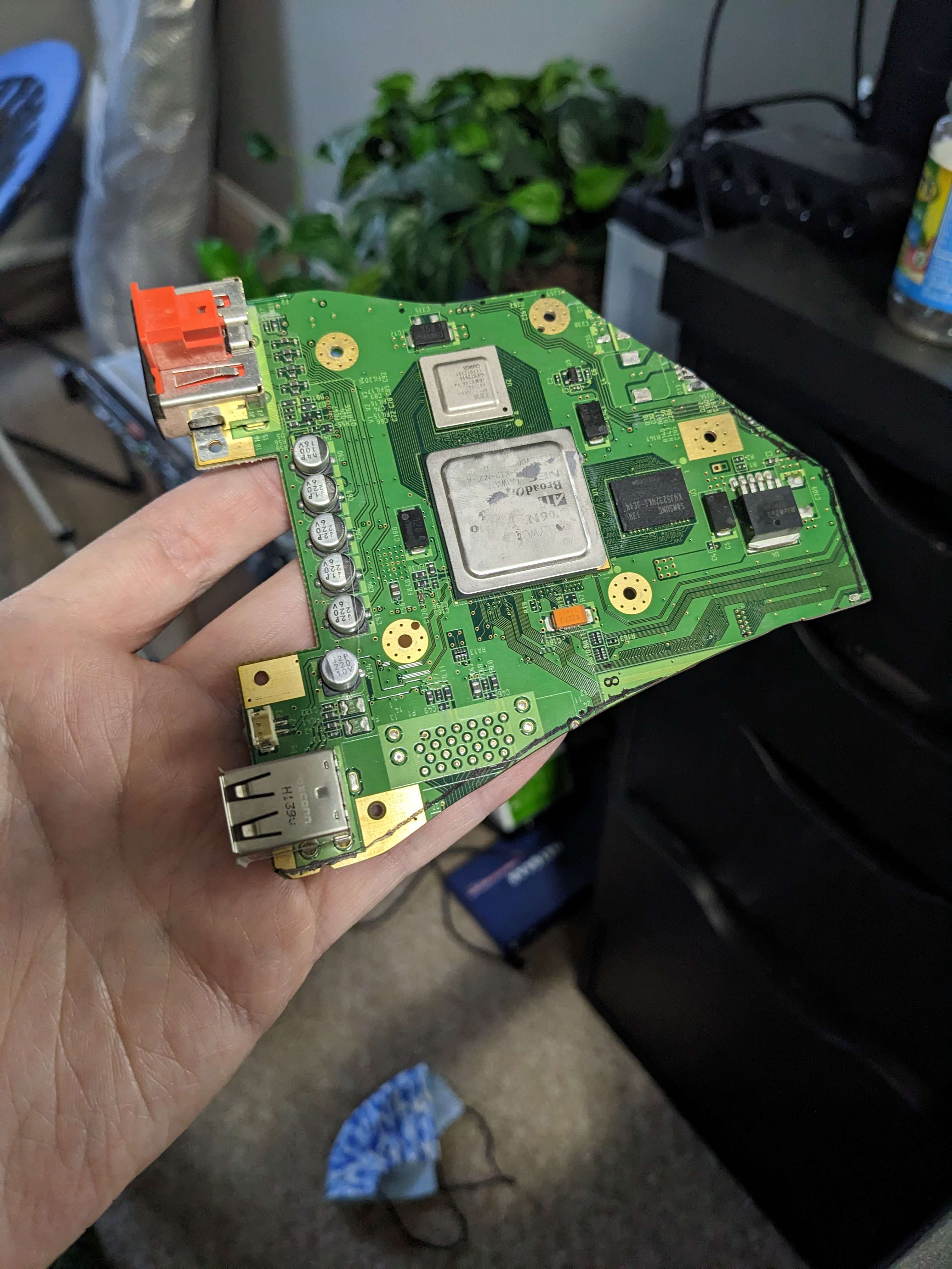
The U10 relocation was the smallest soldering I had ever done, but using 34 gauge wire in a via made it so much easier than I expected.
After wiring up all the voltages from the PSU-Plus I was ready for the moment of truth and plugged it in.
It booted! But it didn't recognize the USB. I double checked the continuity between various parts and the PSU-Plus but everything seemed to be okay, then I checked the voltages coming from the PSU-Plus and found that nothing was coming from 5V. I double checked the PSU-Plus page and realized that I needed to bridge the jumper pads.
After doing all that I plugged it in again and it loaded into RVLoader successfully!
The next step was to model a case so I could 3D print it, however I had very little cad experience and the project stalled here for a long time because I was too intimidated to start.
I lurked the bitbuilt discord for a while and watched other people do their projects, I have to say I am so impressed by this community and the amount of resources and help you put out there.
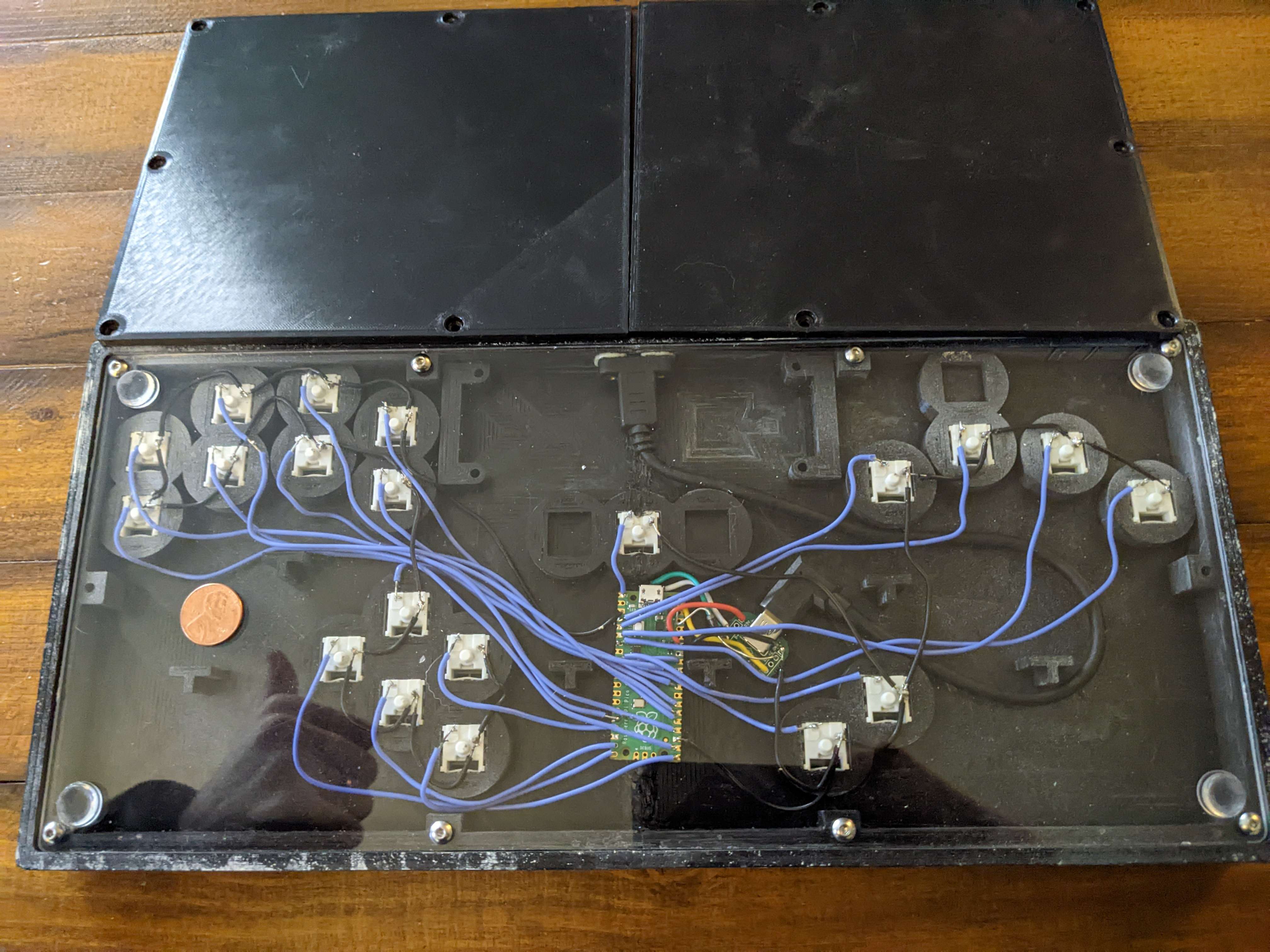
While watching other projects I suddenly had a revelation: I had 3D printed and built several box style controllers for playing melee and I was comfortable with that process, there's a good amount of empty space in these things so I could probably modify a box controller model to fit a wii inside.
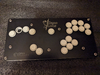
(picture of the controller I currently use for melee, I made it a long time ago so the build quality and soldering is bad but I love it)
The more I thought about it the more possible it seemed, it would have AV out on the front instead of the USB C port for the GCC cable, then three GCC ports on the side so other people could plug in and play with you. It's a portable melee setup that only needs a TV. I thought it would be a very fun thing to bring to events and that's what I needed to push me to actually learn to model a case.
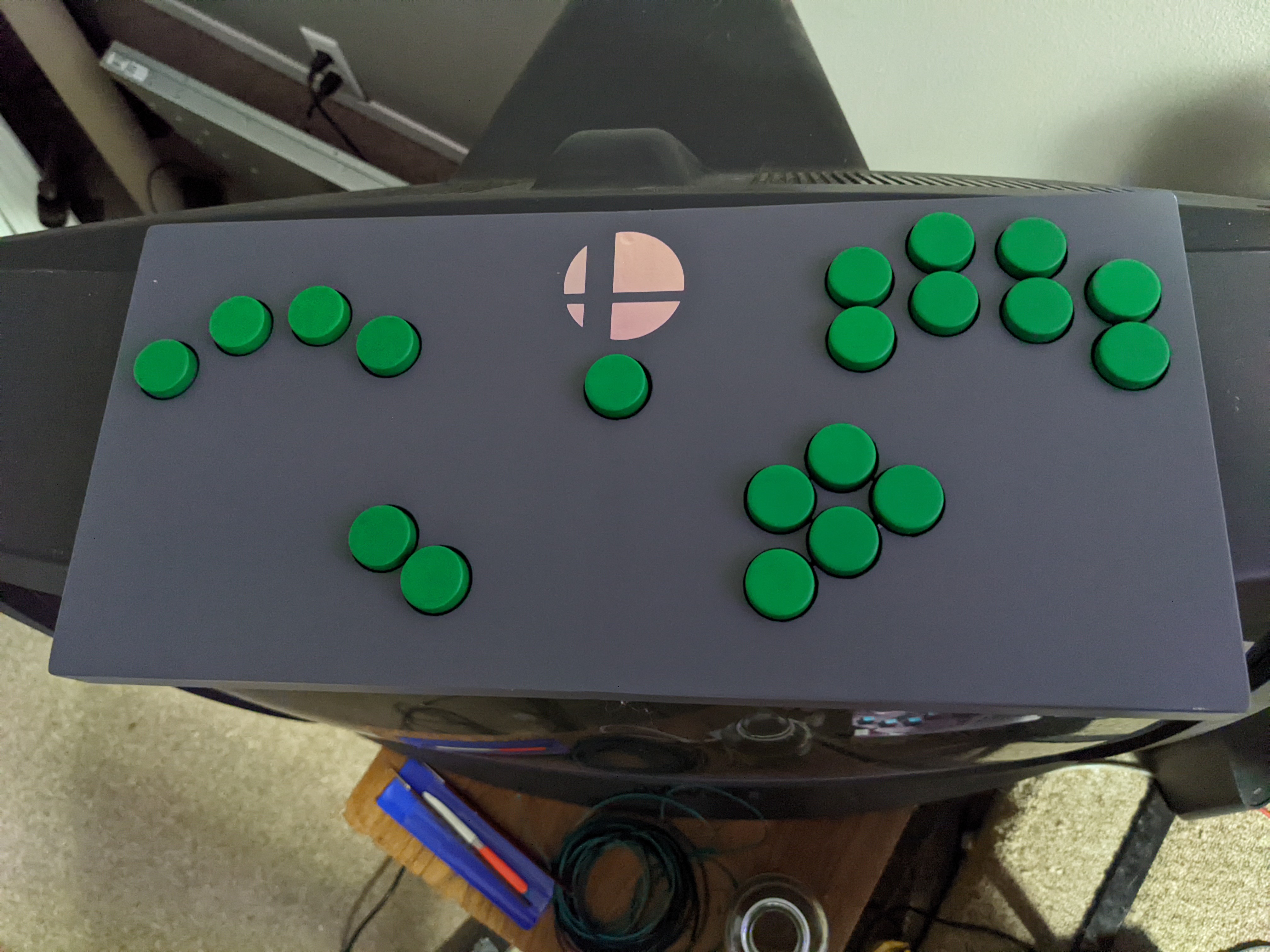
After a good amount of trial and error I've gotten a rough draft of my model design, I had to print out a lot of little prototype parts to test the fits on the GCC ports and RCA female to female connectors I am using. Initially I was going to include both composite and component outputs on the controller, but I realized that component plugs are usually in the back of the TV and I didn't want to have to plug in back there.
Here's my model right now, I've got three GCC ports on the right side and composite out in the front.
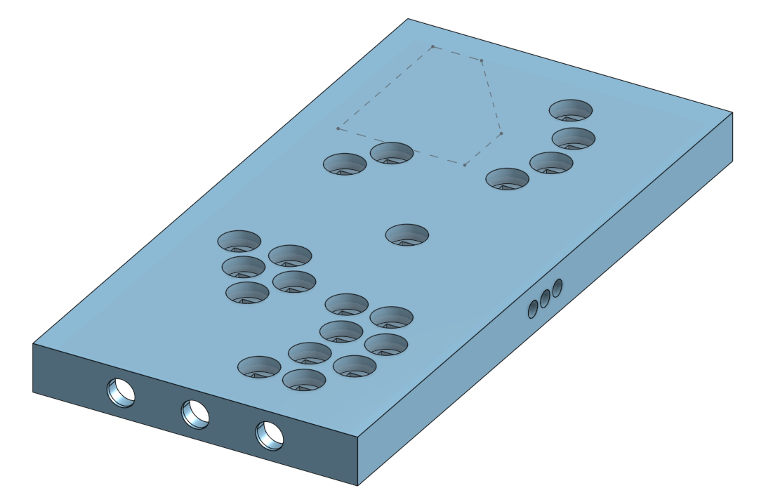
That's where I'm at currently, I printed a test print of just the top layer and found that my button placements need to be adjusted. In theory there is enough room for the wii on the left side of the controller but I'm not certain of what the final dimensions will need to be.
Right now I need to:
-Finalize the dimensions, I could move the button clusters inward to make room for the wii but it's not comfortable if they're too close together. I would like the controller to be as close to normal size as possible but I recognize I'll have to oversize it a little bit, I just need to figure out by how much.
-Put structures inside the controller to mount the wii and raspberry pi to.
-Add screw holes for the bottom cover and possibly support structures for that cover throughout the middle.
-Find a good power bank to allow this thing to run without plugging into a wall, for longer sessions I plan on plugging into the wall but it would be cool to be able to play for an hour or two without that.
-Figure out how I'm going to do cooling with this, this is the part I'm the most unsure about.
-Figure out what color/theme I'm going to go with once it's printed.
-Look into possibly booting straight into slippi or regular nintendont by holding different buttons on boot.
Any comments, opinions, or advice are welcome. Thanks for reading my rambling post!
Someone posted the video later in my local smash bros melee discord and asked if it would be possible to make a melee themed wii case redesign.
I thought this sounded like a fun project so I took another look at what I would need to do it and decided to give it a shot.
My plan was to try a simple wii trim and make something like Jefflongo's wii micro, then paint it up to be themed around the local weekly melee tournament. (https://twitter.com/adamsmashseries)
I ordered a PSU-Plus from CrazyGadget (thanks!) and traded an old CRT I wasn't using for a family edition wii.
At the start of this project I wasn't comfortable with soldering on the motherboard so I wanted to do as little of that as possible and keeping the USB and AV out made it much easier.
Size wasn't as much of an issue on this project as it would be for a portable, so the extra room needed wasn't a problem.
While I was waiting for the PSU-Plus to arrive I took my first shot at making an [ASS] theme for RVLoader.
This thing is only ever going to play melee, so I changed the homebrew menu to only have room for two large choices to pick between
Slippi nintendont is a homebrew for playing competitive melee, then I would have regular nintendont as the second option so you could play melee romhacks or UnclePunch's Training Mode.
(I forgot to take a picture of the theme before I trimmed the wii )
The PSU-Plus arrived pretty quickly, and after a lot of double checking my trim wouldn't cut anything important I went for it.
The trimming was thankfully a lot less difficult than I expected and I had what I thought looked like a pretty good trim.
The U10 relocation was the smallest soldering I had ever done, but using 34 gauge wire in a via made it so much easier than I expected.
After wiring up all the voltages from the PSU-Plus I was ready for the moment of truth and plugged it in.
It booted! But it didn't recognize the USB. I double checked the continuity between various parts and the PSU-Plus but everything seemed to be okay, then I checked the voltages coming from the PSU-Plus and found that nothing was coming from 5V. I double checked the PSU-Plus page and realized that I needed to bridge the jumper pads.
After doing all that I plugged it in again and it loaded into RVLoader successfully!
The next step was to model a case so I could 3D print it, however I had very little cad experience and the project stalled here for a long time because I was too intimidated to start.
I lurked the bitbuilt discord for a while and watched other people do their projects, I have to say I am so impressed by this community and the amount of resources and help you put out there.
While watching other projects I suddenly had a revelation: I had 3D printed and built several box style controllers for playing melee and I was comfortable with that process, there's a good amount of empty space in these things so I could probably modify a box controller model to fit a wii inside.
(picture of the controller I currently use for melee, I made it a long time ago so the build quality and soldering is bad but I love it)
The more I thought about it the more possible it seemed, it would have AV out on the front instead of the USB C port for the GCC cable, then three GCC ports on the side so other people could plug in and play with you. It's a portable melee setup that only needs a TV. I thought it would be a very fun thing to bring to events and that's what I needed to push me to actually learn to model a case.
After a good amount of trial and error I've gotten a rough draft of my model design, I had to print out a lot of little prototype parts to test the fits on the GCC ports and RCA female to female connectors I am using. Initially I was going to include both composite and component outputs on the controller, but I realized that component plugs are usually in the back of the TV and I didn't want to have to plug in back there.
Here's my model right now, I've got three GCC ports on the right side and composite out in the front.
That's where I'm at currently, I printed a test print of just the top layer and found that my button placements need to be adjusted. In theory there is enough room for the wii on the left side of the controller but I'm not certain of what the final dimensions will need to be.
Right now I need to:
-Finalize the dimensions, I could move the button clusters inward to make room for the wii but it's not comfortable if they're too close together. I would like the controller to be as close to normal size as possible but I recognize I'll have to oversize it a little bit, I just need to figure out by how much.
-Put structures inside the controller to mount the wii and raspberry pi to.
-Add screw holes for the bottom cover and possibly support structures for that cover throughout the middle.
-Find a good power bank to allow this thing to run without plugging into a wall, for longer sessions I plan on plugging into the wall but it would be cool to be able to play for an hour or two without that.
-Figure out how I'm going to do cooling with this, this is the part I'm the most unsure about.
-Figure out what color/theme I'm going to go with once it's printed.
-Look into possibly booting straight into slippi or regular nintendont by holding different buttons on boot.
Any comments, opinions, or advice are welcome. Thanks for reading my rambling post!