Worklog PiR8_BTY's N64 Portable Control Deck (N64HH)

Joined
Apr 12, 2020
Messages
131
Likes
260
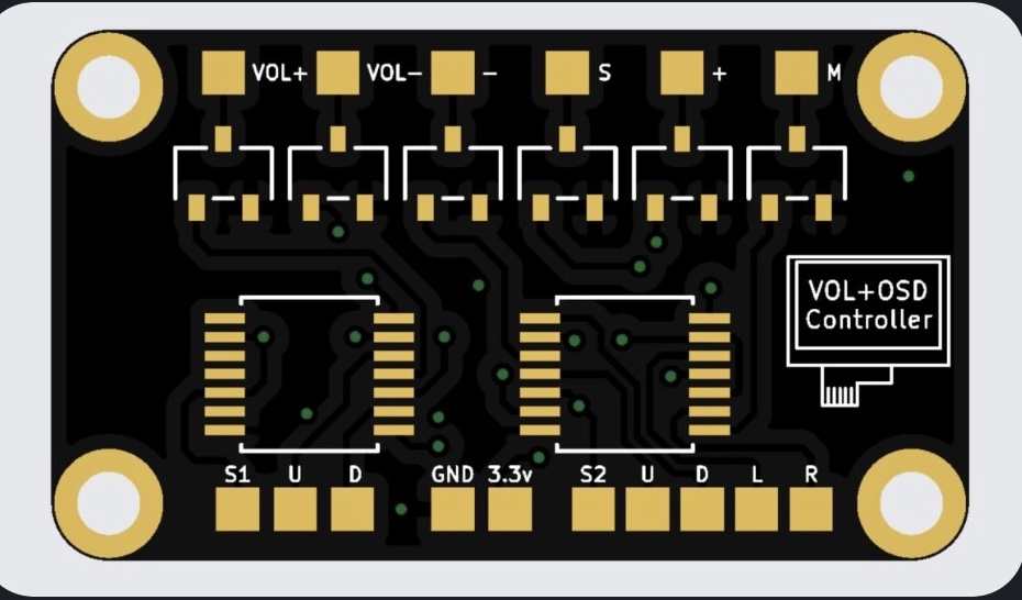
Update! I wired up the @CrazyGadget OSD control board (used in this case for volume control) and continued to wire everything up. I checked all the connections and noticed I accidenatlly wired C-Left to GND and GND to C-Left. All fixed. Waiting on a @atkfromabove RCP flex and then I should be set to continue.
IMG_0919.JPG

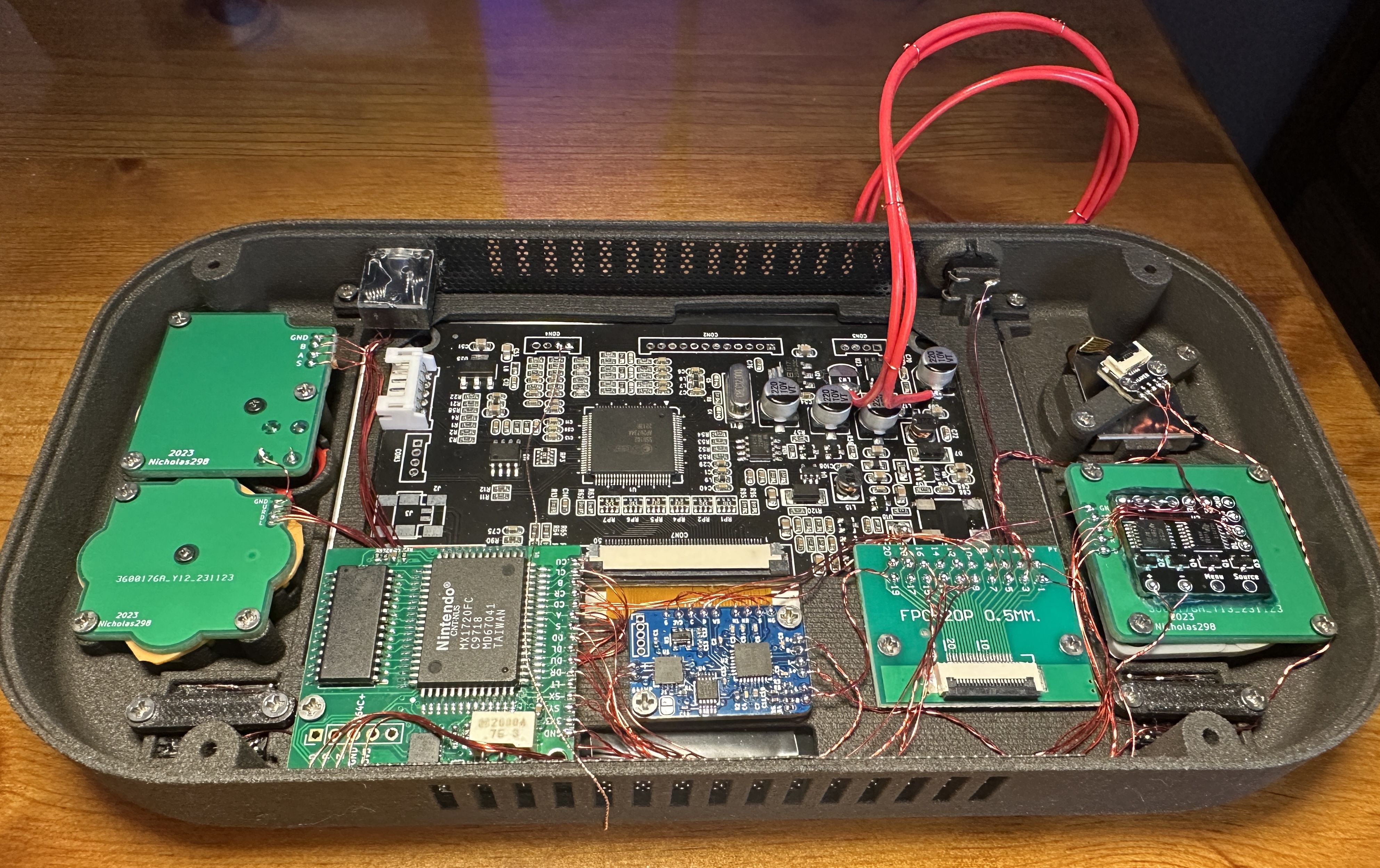
FYI, I know @Nicholas298 teased a VOL + OSD board, but I couldnt wait.
IMG_0909.jpeg
 
Last edited:
Joined
Apr 12, 2020
Messages
131
Likes
260
Let there be light (and charging)! I harvasted the thermistor and RGB LED from my now abandoned 4th Gboy kit as these components fit the vintage of the RVL board perfectly. Plus I plan to do an entire 4layertech Gboy component build someday with a hint of under-volting and a laminated screen.
IMG_0937.jpeg

I trimmed a little bit of the mounting bracket to make it fit perfectly. And the best part is the led itself keys precisely inside the 2x2mm square hole. I was thinking about sourcing a square 2x2mm light pipe to help diffuse the light though. I know your supposed to use a traditional led in the expansion slot behind, but I like this solution.
IMG_0939.jpeg

Additionally, I originally ordered 603 (Imperial) passives for the sparkleboard and I thought I could repurpose them for the control board designed by Gman. Unfortunately his design calls for 402 (Imperial) passives for the controller board. I need to redo my board because it did not pass continuity tests and I dont want my SMD components to be doing gymnastics.
 
Last edited:
Joined
Apr 12, 2020
Messages
131
Likes
260
Update! It would seem the big N was busy making at a few revisions of the jumper pak. With a 96,97, and 98 pcb date identified so far. Looks like the one with the (lower) 4 surface mount caps is the most desirable for trimming. Especially cause you can scratch away the solder mask at the higher trace and just add a jumper wire.
IMG_1070.jpeg

IMG_1072.jpeg

IMG_1095.jpeg

IMG_1096.jpeg

Next, I replaced the controller breakout board by populating, flashing and adding the CR0402 (imperial) passives. The silk screen on the MX chips are completely different.
IMG_1083.jpeg

Finished up the wiring for the FFC connectors on both sides and added a nice label for future reference.
IMG_1085.jpeg

IMG_1094.jpeg

now I need to work on testing the mobo, adding RAM, trimming the cartridge portion, wiring up the mobo with the help of an rcp flex cable, and trimming the jumper pak. Hopefully my screen isnt a dud. I also have some extra goodies in the wings, but i’ll save that for later!
 
Last edited:

CrazyGadget

Crazy Helpful, CrazyGadget
.
Joined
Jun 6, 2020
Messages
611
Likes
879
Location
Downing's Closet
Portables
???
Just a heads up, I believe you have to trim even more off, down to the row of vias (through the capacitor). You'll have to restore the one plane you cut off. That's going off of pics of Nicholas's original build, as well as Gunnar's
 
Joined
Apr 12, 2020
Messages
131
Likes
260
Just a heads up, I believe you have to trim even more off, down to the row of vias (through the capacitor). You'll have to restore the one plane you cut off. That's going off of pics of Nicholas's original build, as well as Gunnar's
I thought they both had revision NUS-RTC-10 where there is no cap that needs to be removed up to the vias. Then they just ran a jumper wire on that lone high trace. But yeah, it probably will either barely fit or not at all. :!:
 
Last edited:
Joined
Apr 12, 2020
Messages
131
Likes
260
*Update*! I noticed my D-Pad wasnt working correctly and after a conversation with gman, he pointed me in the right direction. The N64 D-Pad has 2 little protruding nubs that need to be removed with flush cutters to work properly. These nubs are on the top of the D-PAd as shown in the photo.
IMG_1434.jpeg

IMG_1432.jpeg

I got some more goodies from JLC. I found out how to order tiny parts! Just connect them with break away plastic like a modeling kit! I got SLS nylon mounting brackets and resin buttons to match the smoothness of the stock oem buttons.

Next, I fixed the looseness of the usb-c connector by adding some shims.

Additionally, I tried to test my trim but my screen of course is DOA. Now my build is waiting on a replacement screen gosh darnit. Till next time.
 
Top