
- Joined
- Oct 26, 2022
- Messages
- 15
- Likes
- 11
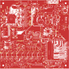
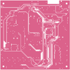
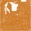
The goal of this project is to create an all in one PCB that would provide everything needed to create a portable console. The board will include all of the common components featured in portables. As it uses many open source projects as references, credits will be listed in the description or at the end of this post. The board itself is 100 x 100 mm and six layers, stacked signal, ground, power, ground, signal, signal. To mitigate heat a central controller will allow the disabling of unused components. The board will include the following, usb-c port, internal and external power system, audio system with left/right speakers and headphone jack, RGB to VGA upscaler, LCD display controller, gamepad component with connectors to buttons, an SBC to allow for basic emulation and file management, internal SD cards, and a system of USB switches.
Details of components included:
* This may not be necessary if I am able to adjust it via SDA/SCL from the SBC but will be included in this board until I figure that out.
This is a test board as I am not sure how certain things will work as such there are several redundancies or connections that will be removed in the final board. This is my first board of such complexity and I welcome feedback and holes being poked in it so I can fix whatever I have overlooked. For the most part I have just taken several working projects and condensed them all into one board and then interconnected them. The connections in theory should work but I will only know once the board is complete. I have completed the first revision of the schematic and the board but want to post to find any flaws or errors before ordering anything.
Credits
GMAN for his PMU and UAMP
YveltalGriffin for the Shinobi Scaler
BocuD and KerJoe for the work on RTD2660
Aurelio92 for the GC+
Mcranford13 for the PS2+
Bigbass1997 for the PIC-CNT64
Petit-miner for the Blueberry Pi
I am sure there are more that I am forgetting but I have been working on and off for months and am sure I have forgotten people whose work I was inspired by or referenced for that I apologize.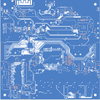
Details of components included:
- Usb -c port
- Main controller
- The main controller will be an Atmega328PB. This will control most of the systems.
- Internal power system
- Five components provide internal power, two TLV62095 provide 3v3 and 1v8 for most components, A TPS61230 provides 5v for some components,an LP5907MFX provides 2v5 for the Audio IC, and an AXP203 provides all the power needed for the SBC and its peripherals as well as handling battery charging.
- External power system
- Eight components provide external power for a multitude of consoles, six TLV62095 provide power of 1v, 1v15, 1v25, 1v8, 3v3,3v5. Two LP2992IM5 provide 1v75 and 2v5. These should cover most consoles, however a connection for the VSYS is available if needed.
- Audio system
- The Audio system is based on GMANs Uamp and uses a LM49450
- Upscaler
- The Upscaler is an integrated Shinobi scaler from YveltalGriffin
- LCD controller
- The LCD is a RTD2660 designed using BocuD’s work and KerJoe’s Github as reference
- Gamepads
- The gamepad on the board is only the ICs with two external connectors for the buttons, There are two ICs connected together so all of the inputs go together, a PIC16 is used for the external consoles and a RP2040 is used as a usb gamepad for the SBC.
- SBC
- The SBC is an Allwinner V3s which is used in the blueberry PI, it was chosen for its low power use and ease of design. Though low powered after seeing the Funkey handheld I am confident that it should be enough to emulate older systems. One issue is that it doesn’t natively have VGA support luckily I can use three SN74ALVs to output RGB from the LCD outputs
- SD cards
- There will be two internal SD cards one connected to the SBC and another for the external consoles it will be converted to Usb by a CP8121N
- Usb switches
- Three usb switches will be used to allow multiple connections to use the Usb-c port. Two FSUSB74 4 to 1 switches and TS3USB22 2 to 1 switch. A manual switch is used to control some I/O for programming purposes. I was going to explain in detail how all of the connections work but it was too wordy so I’ll just summarize.
- When power is off and programming is off the USB port goes to game SD card
- When power is off and programming is on the USB port goes to the TS3USB.
- When above a manual switch will allow for the selection of either the ATMEGA or RP2040 to allow for programming.
- If power is on and the programming switch is on the ESP will access the port.
- Default when power is on the USB port goes to the SBC and the game SD card goes to an external connection for consoles.
- A signal can be sent while power is on for the SBC to access the game SD card
- Other ICs - These are other ICs that provide extra functionalities.
- Attiny85 - used for fan control.
- MAX17055 - Battery gauge.
- RTL8723BS - provides wifi and bluetooth for the SBC.
- ESP8266 - used by the scaler for wifi programming*.
- STP08CP - a shift register to control each of the external power ICs individually.
* This may not be necessary if I am able to adjust it via SDA/SCL from the SBC but will be included in this board until I figure that out.
This is a test board as I am not sure how certain things will work as such there are several redundancies or connections that will be removed in the final board. This is my first board of such complexity and I welcome feedback and holes being poked in it so I can fix whatever I have overlooked. For the most part I have just taken several working projects and condensed them all into one board and then interconnected them. The connections in theory should work but I will only know once the board is complete. I have completed the first revision of the schematic and the board but want to post to find any flaws or errors before ordering anything.
Credits
GMAN for his PMU and UAMP
YveltalGriffin for the Shinobi Scaler
BocuD and KerJoe for the work on RTD2660
Aurelio92 for the GC+
Mcranford13 for the PS2+
Bigbass1997 for the PIC-CNT64
Petit-miner for the Blueberry Pi
I am sure there are more that I am forgetting but I have been working on and off for months and am sure I have forgotten people whose work I was inspired by or referenced for that I apologize.