
Discussion Where do I begin? (NOW FLIP'S FIRST WORKLOG)
- Thread starter tealflip
- Start date
tealflip
.
- Joined
- Oct 27, 2022
- Messages
- 66
- Likes
- 51
Howdy! Update time:
Firstly, the IRS pulled their heads out of their asses, and got the money to us. Secondly, multiple parts have been ordered.
3D Printer
PMS Plus
I plan to get started trimming next week as it is my April Vacation. I double checked measurements for gamecube ports thanks to a lovely pre-made model, and the sizes check out. The motherboard I have not been able to test yet, but I will do so after I print. Also, S/O to a few people for their help so far, ur help will not go unmentioned:
Thommothy: Offering guidance picking out a USB C board and how to power it. Still looking for a good board candidate but I'll keep an eye out.
CrazyGadget: Quite literally being a mad lad to include multiple U10 chips with my PMS Plus board. Thank you so much!
Wrental: Offering emotional support during the case design.
Ylveltal: Helping with ideas and how to approach a lot of parts of this project, currently helping me rn ironically lmao.
And of course, to Nold for the original design plans. This case is just a glorified version of his, couldn't do it without him.
The Fliptendo will COME ALIVE!
- Joined
- Feb 18, 2024
- Messages
- 69
- Likes
- 25
- Portables
- working on No.1
Like the name!The Fliptendo will COME ALIVE!
tealflip
.
- Joined
- Oct 27, 2022
- Messages
- 66
- Likes
- 51
Heres the not so daily update for this project:
All that is left is the power button, and then.... it's finished? Other than maybe a couple artistic details, it's done.... I.... did it? Thank you everybody for your help, this is gonna go crazy once it's done.
P.S: USB C Board is ordered, gonna order some buttons or harvest from other electronics I have, we are getting VERY close.
- Joined
- Feb 18, 2024
- Messages
- 69
- Likes
- 25
- Portables
- working on No.1
nice
tealflip
.
- Joined
- Oct 27, 2022
- Messages
- 66
- Likes
- 51
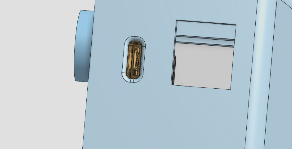
Double checked, they are good. Tomorrow I will begin wiring and printing out the case.View attachment 32867
These are very heavily rounded. How good are these? How can I check for shorts between voltage lines?
Yeah those figures are within margin
tealflip
.
- Joined
- Oct 27, 2022
- Messages
- 66
- Likes
- 51
Good and bad news:
One, shell came out WONDERFULLY. Minor blemishes but for a first print, it worked well.
Secondly, quality didnt matter since some measurements with the standoffs were WRONG! Im gonna take a bit of a break to relax and come back to this once my mental sanity is back in check.
One, shell came out WONDERFULLY. Minor blemishes but for a first print, it worked well.
Secondly, quality didnt matter since some measurements with the standoffs were WRONG! Im gonna take a bit of a break to relax and come back to this once my mental sanity is back in check.
tealflip
.
- Joined
- Oct 27, 2022
- Messages
- 66
- Likes
- 51
Update: Did some more checks, fixed the standoffs *hopefully* and a couple other things I realized didnt fit. A new USB C breakout board is on the way since we may or may not of fucked the original one up.... whoops... anyway, new case is going now.
tealflip
.
- Joined
- Oct 27, 2022
- Messages
- 66
- Likes
- 51
Good news: wired up. Bad news: no boot. Atleast I believe so.
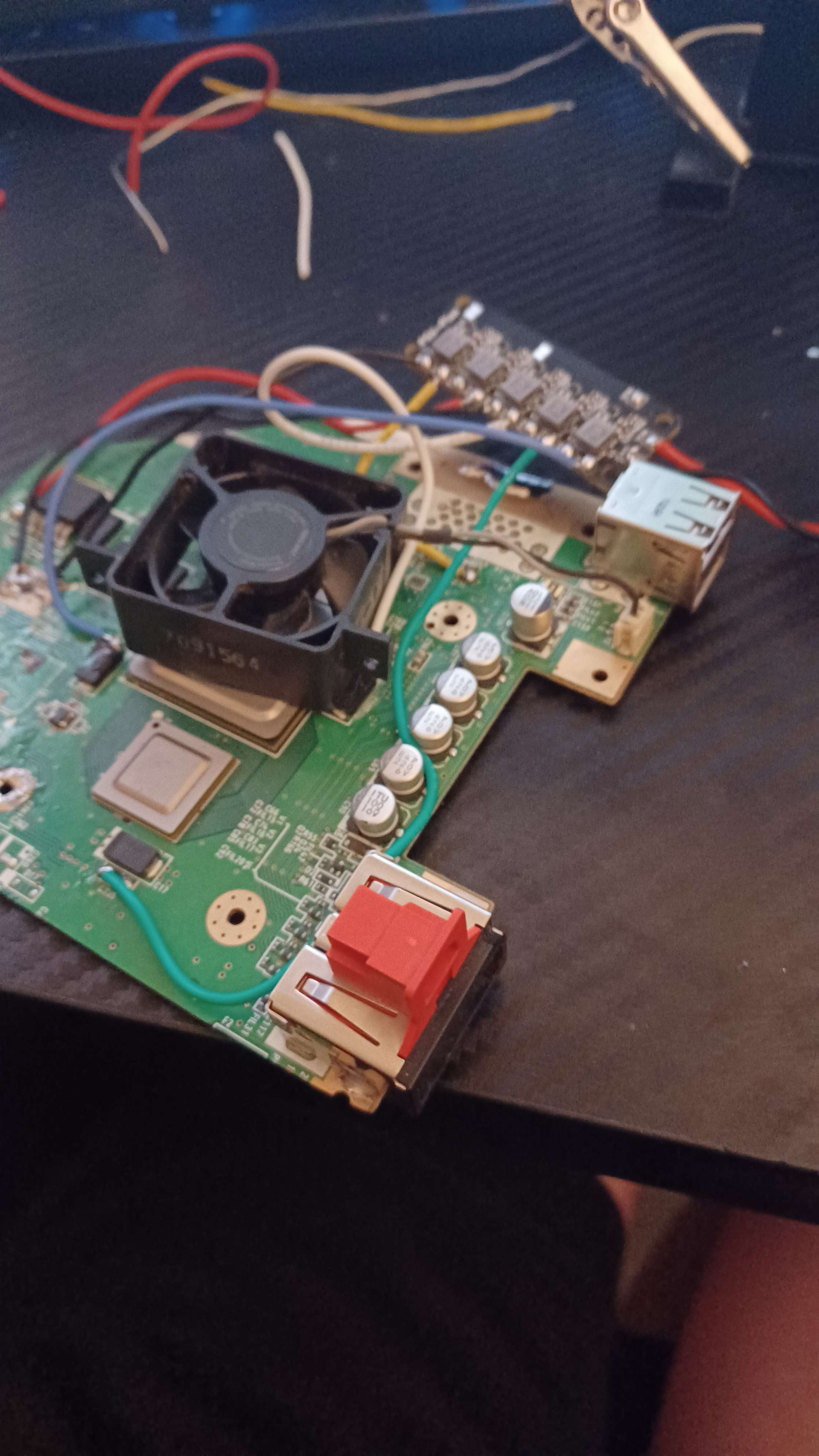
See, the cpu and gpu are warming up. However, no fan spin, no video, etc. I am gettin the correct voltages out of the PSU-PLUS, have two ground wires installed, and I am inputting 12v at 2A into the board. Any help is not just appreciated, but NEEDED.
See, the cpu and gpu are warming up. However, no fan spin, no video, etc. I am gettin the correct voltages out of the PSU-PLUS, have two ground wires installed, and I am inputting 12v at 2A into the board. Any help is not just appreciated, but NEEDED.
The fan isn't spinning because you haven't soldered the 5v jumper, and with the LDO still on the board you don't need to wire the 1.8v line from the PSU-PLUS
tealflip
.
- Joined
- Oct 27, 2022
- Messages
- 66
- Likes
- 51
Dumb question, where is the 5v jumper for the fan? Or in other words, how should I approach this? I connected 5v to the capacitor pads at c49 *bottom of it*The fan isn't spinning because you haven't soldered the 5v jumper, and with the LDO still on the board you don't need to wire the 1.8v line from the PSU-PLUS
Last edited:
The 5v jumper is this pair of pads on the PSU-PLUS. Put a solder blob across both pads to allow voltage to flow to the 5v regDumb question, where is the 5v jumper for the fan? Or in other words, how should I approach this? I connected 5v to the capacitor pads at c49 *bottom of it*