
- Joined
- Nov 4, 2019
- Messages
- 24
- Likes
- 169
This guide is the culmination of months of research and work and a failed contest entry.
I have put a lot of time and effort into this guide and there were a LOT of ups and downs, but I hope it is worth it as at the end of the day it shows you everything you need to know to do something that was anecdotally impossible for years, and that is pretty darn cool.
DISCLAIMER:
As always there is risk involved in doing any project like this. Follow along at your own risk.
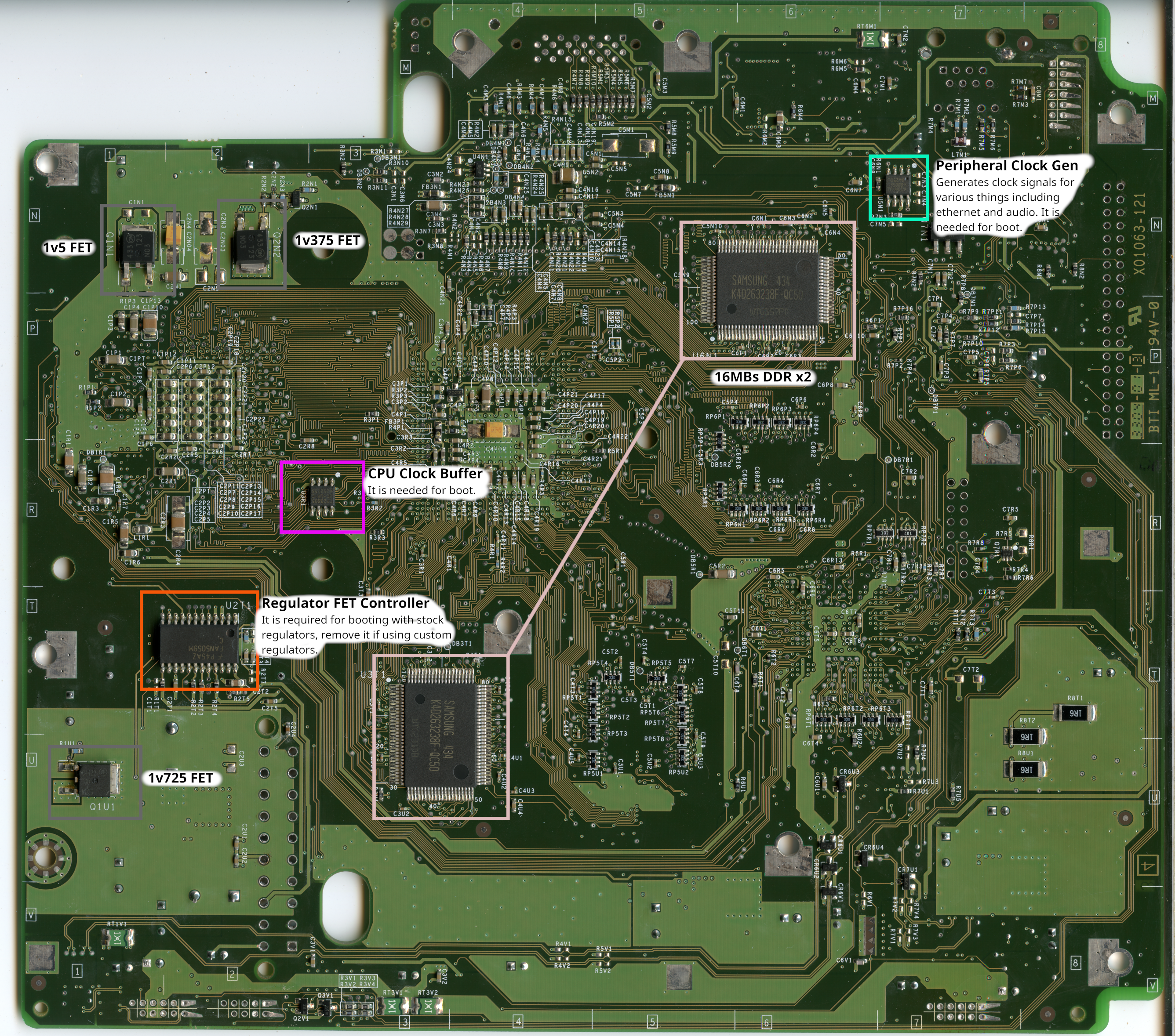
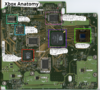
Additionally there are 3 retail Xbox motherboards. This guide is only for the 3rd and final board revision, X01063-121 or 121 for short. The 2 older PCBs are not suitable for portable use, they cannot be cut down as densely (or at all), and they draw up to 50% more power, and they lack a variety of hardware that amounts to making the 121 board perfect for the job. All research and documents pertain to the 121 board, and this is what is detailed in the Compendium document as well.
The following is the "anatomy" of the 121 motherboard, please get acquainted with it before proceeding.

USB RELOCATION:
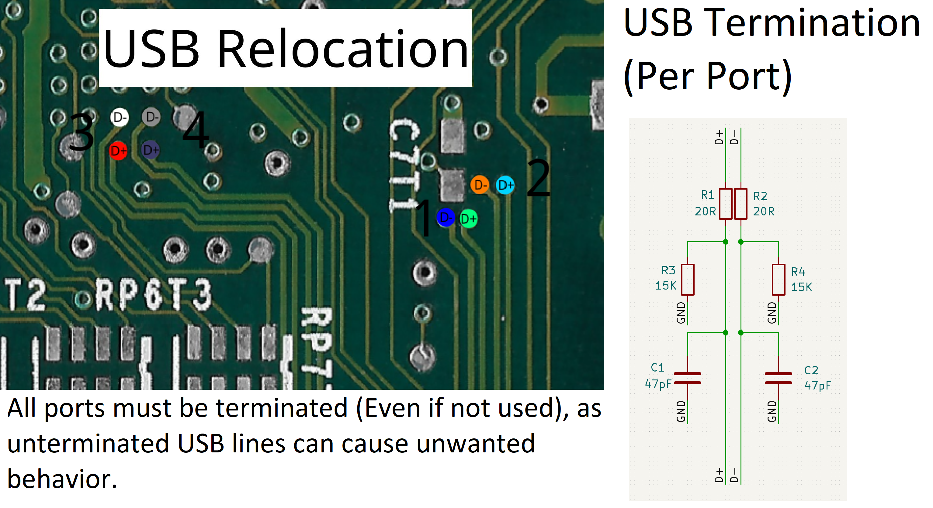
USB is used by the Xbox for controllers, and memory cards, and is a necessary relocation for proper function of the Xbox.
If each lane is not terminated, some BIOS and pieces of software can freeze, crash or in some cases not detect controllers. (Even if you terminate the lane you are using, if the others aren't terminated this can occur.)
Below you can find a diagram detailing USB via "pinout" as well as how to terminate each port.
XCALIBUR REBUILD:
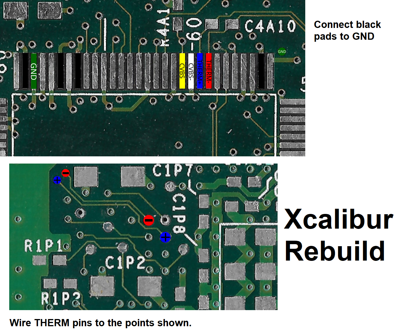
The Xcalibur chip is a custom video encoder that also handles tasks such as monitoring the CPU temp and reporting to the SMC when an overheat occurs.
It is at this time required for the Xbox to even boot. For the basic trim in this guide some vias are severed, so it will need some pins reconnected and rebuilt.
I2S AUDIO:
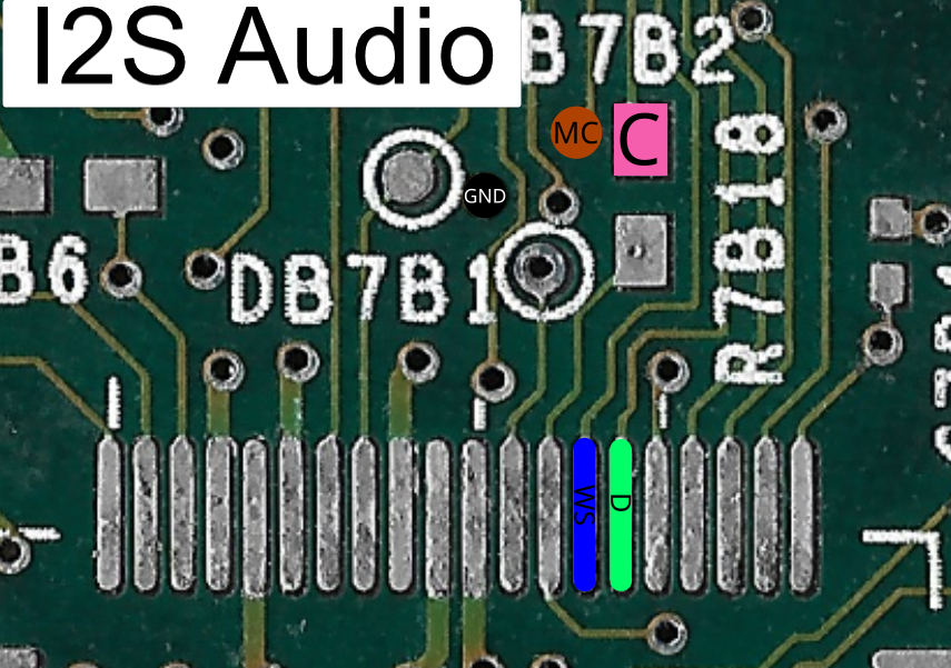
The Xbox MCPX outputs 2 types of digital audio, SPDIF, and AC97. SPDIF is routed straight to the AV output port for some AV output modes, and the AC97 is converted for analog audio.
On previous boards there is a dedicated AC97 DAC for this job, however the 121 uses the custom Xyclops SMC to convert AC97 to I2S, which then goes to a cheaper I2S DAC.
Thanks to this we can very easily use crisp digital audio in our portables.
It is possible to use the U-AMP2 to do this, however it isn't implemented just yet.
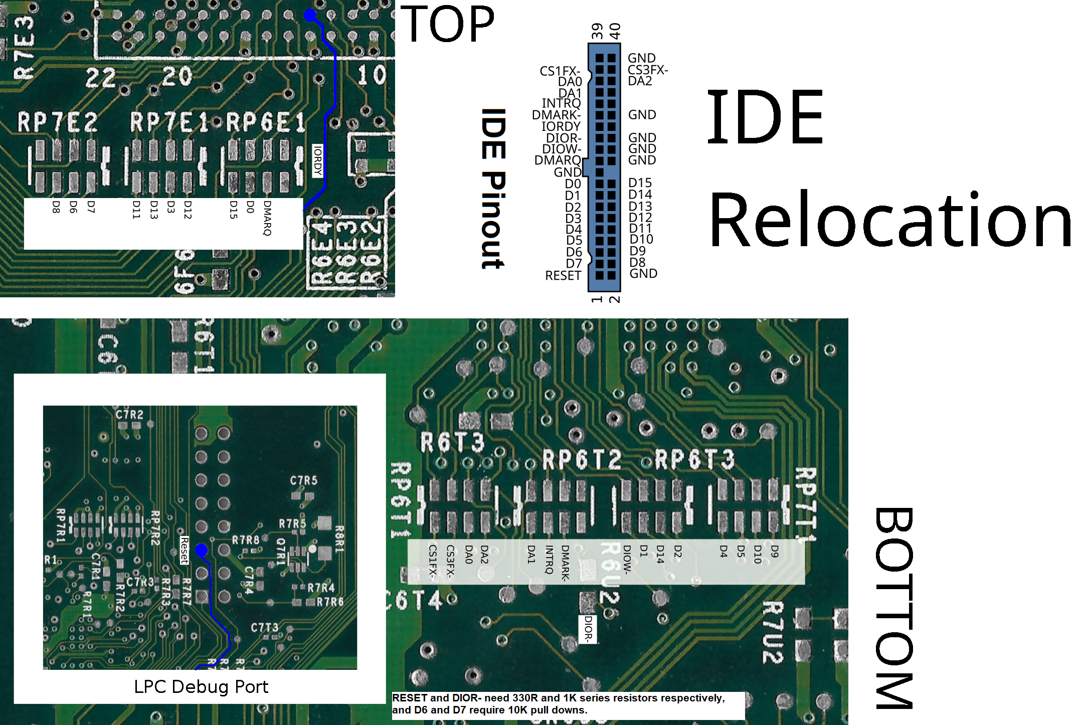
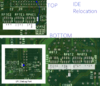
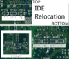
IDE RELOCATION:
IDE is used for the DVD and HDD drive connections in a stock unmodified Xbox.
It is currently the only means of attaching storage to the Xbox, as such it is a required relocation for an Xbox portable.
An Xbox will boot without storage but only as far as the boot animation and a subsequent error screen. (So you can test a trim without, but not really use it)
The DVD drive is similarly a requirement for a stock BIOS, so a modified BIOS that patches it out is required to bypass an error screen.
The IDE relocation is sorta involved without a flex but it is totally doable with or without one.
The following diagram will tell you everything you need to know.
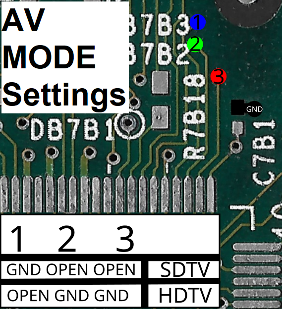
AV MODE:
The video output signal/type is set based on the state of 3 pins on the Xyclops SMC.
The following diagram is far from comprehensive as far as what all modes it can do, but it should be sufficient for portable use.
If no mode is set, the Xbox will fail to boot and flash the LED orange and green, so you must have at least some AV mode set.
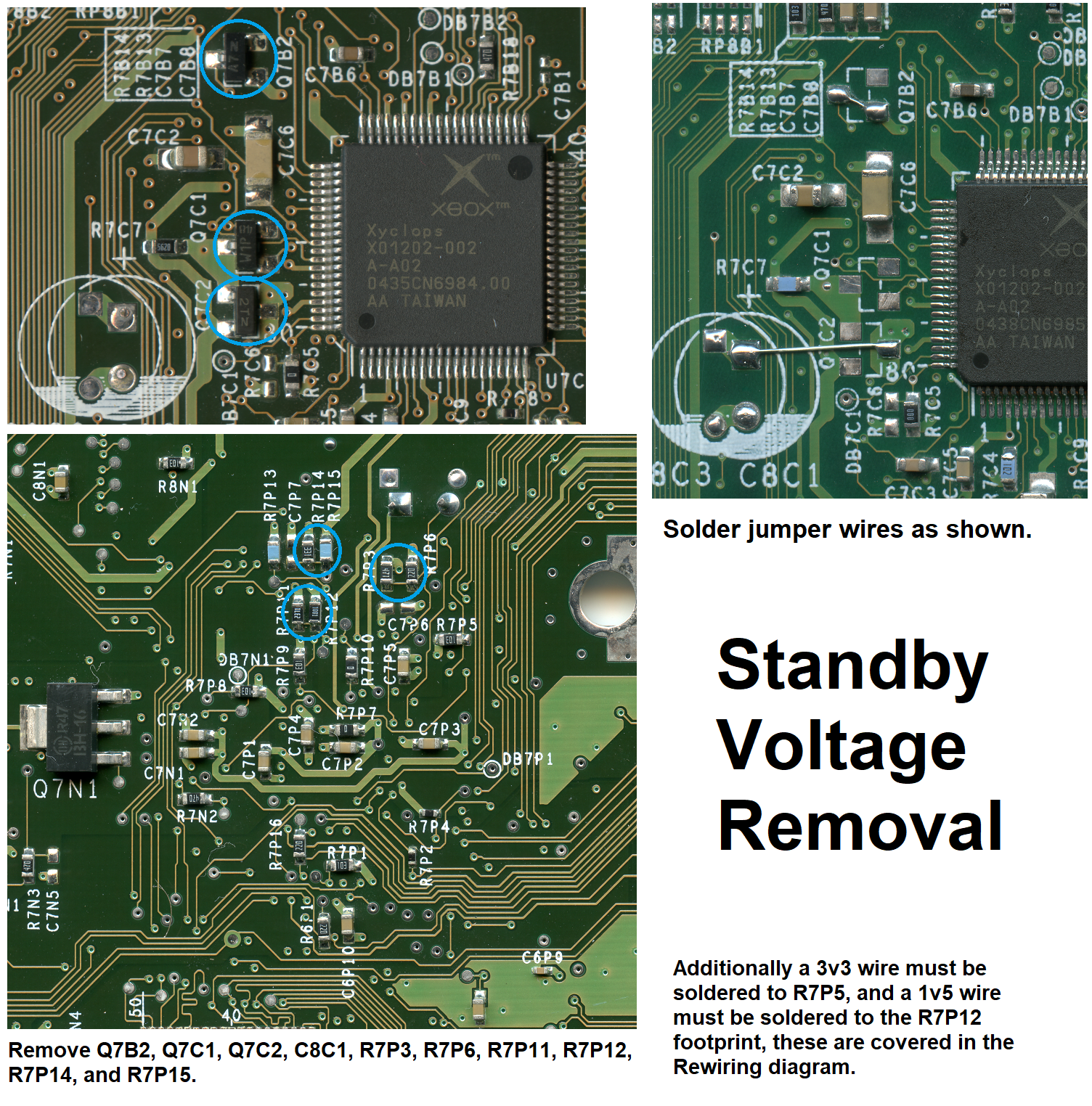
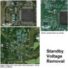
STANDBY REMOVAL:
In order to boot the Xbox without the stock regulators or PSU (Additionally because a continuous ~30mA draw isn't ideal for a portable device), we must remove the need for standby voltage.
While it didn't seem like it at the time while researching, it is relatively straight forward. It is recommended to do this mod and test it before you trim. (The PSU will need to be jumpered on)
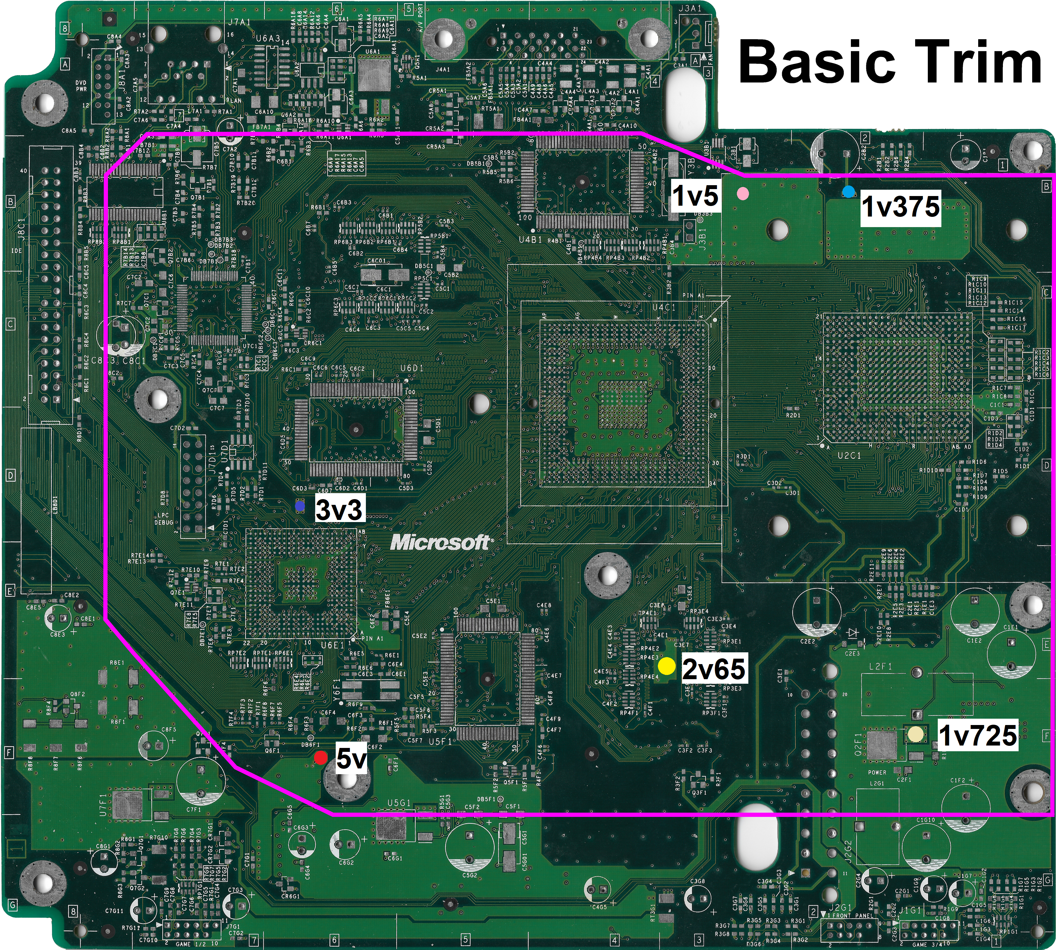
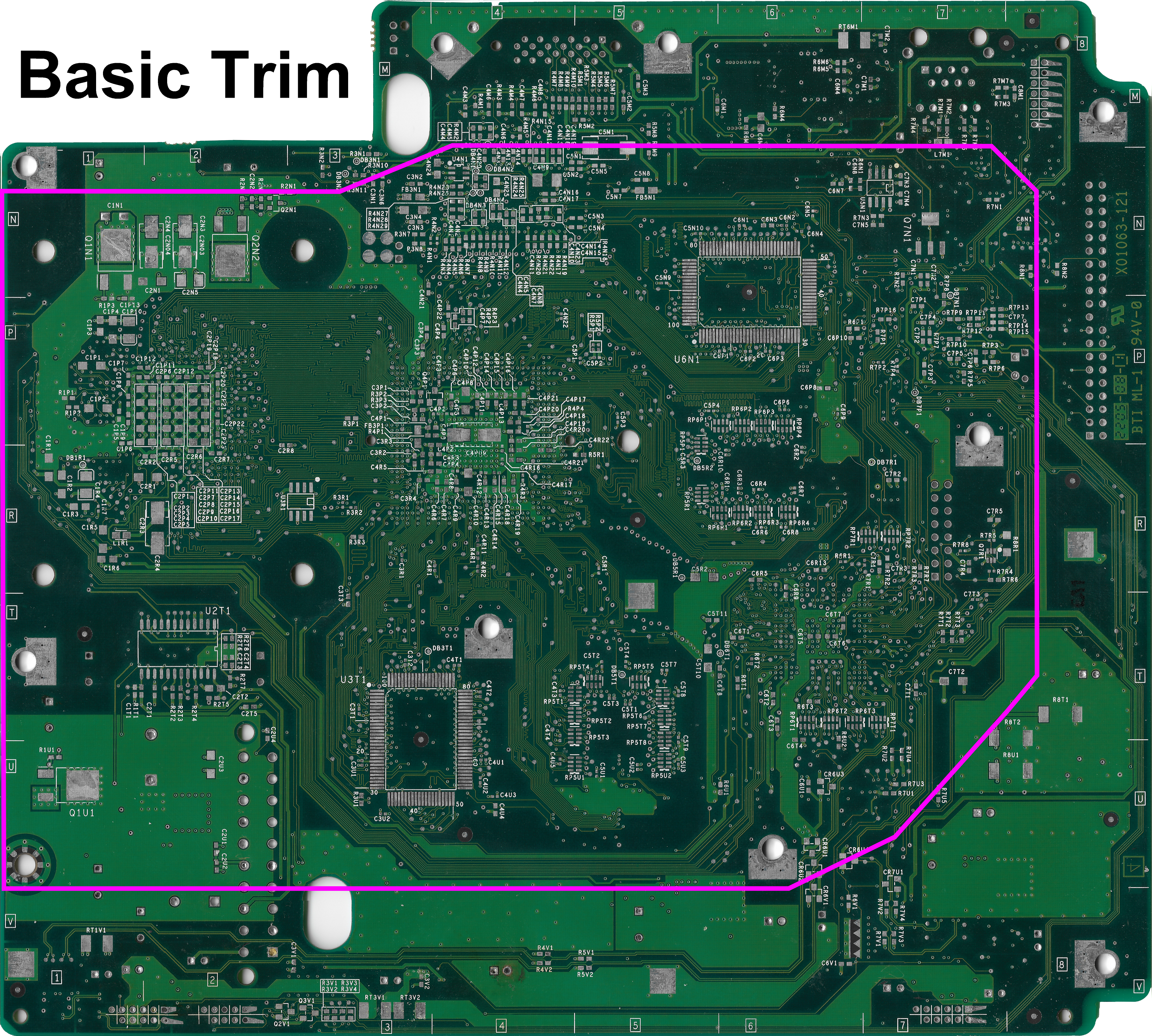
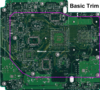
TRIMMING:
Before trimming it is recommended that you have a standby voltage free hardmodded (With a no-DVD BIOS) motherboard that is tested and working.
You should tape off at least the BGA chips, but preferably the whole area inside the trim line to save on conductive dust clean up later.
Use the following diagrams to mark out your trimline, and then cut slightly outside the line with a Dremel and a diamond cutting wheel, and then sand your way in to prevent damage to anything important.
Once trimmed you will need to sand the edges at an angle to separate the 4 copper layers of the PCB and remove/prevent shorts. It is recommended to work your way up to at least 600 grit in increasing increments.
During this process you should keep checking the various voltage rails for shorts with a multimeter in resistance mode, "continuity" mode is not sensitive enough for this and will give false positives.
A rough number for what resistance each rail should be is as follows:
* 1v375: 10Ω
* 1v5: 70Ω
* 1v725: 40Ω
* 2v65: 28Ω
* 3v3: 35Ω
* 5v: 3MΩ
(Most auto ranging meters won't be able pin down 5v resistance because it is so high, so just make sure it is above 0Ω.)
It will vary from board to board by some amount but the important thing is that they are close and even more so that they are above 0Ω.
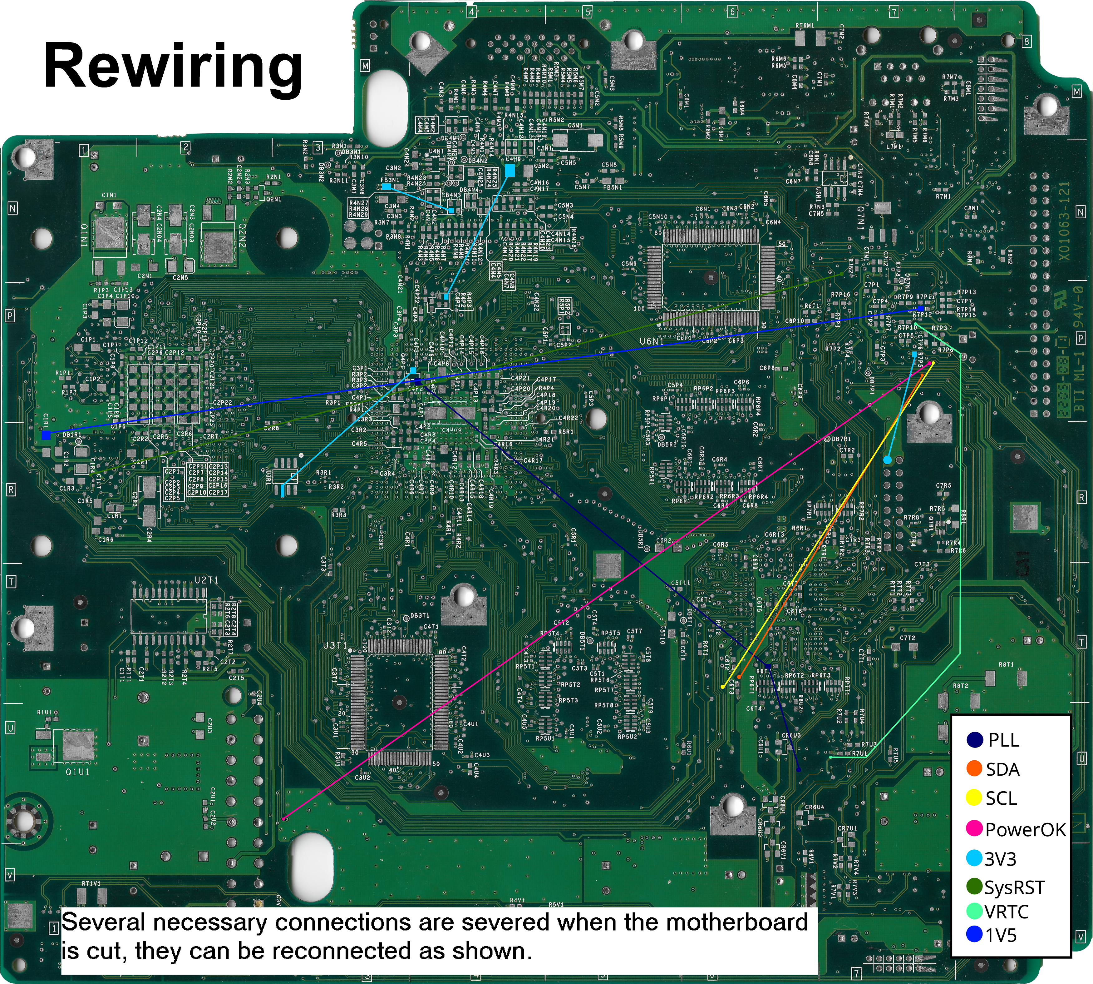
REWIRING:
When the board is trimmed a handful of connections are severed, these are required for the Xbox to boot and as such must be reconnected prior to using the trim.
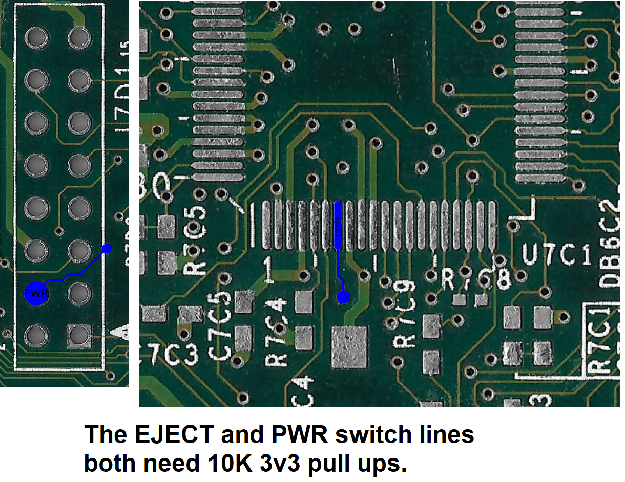
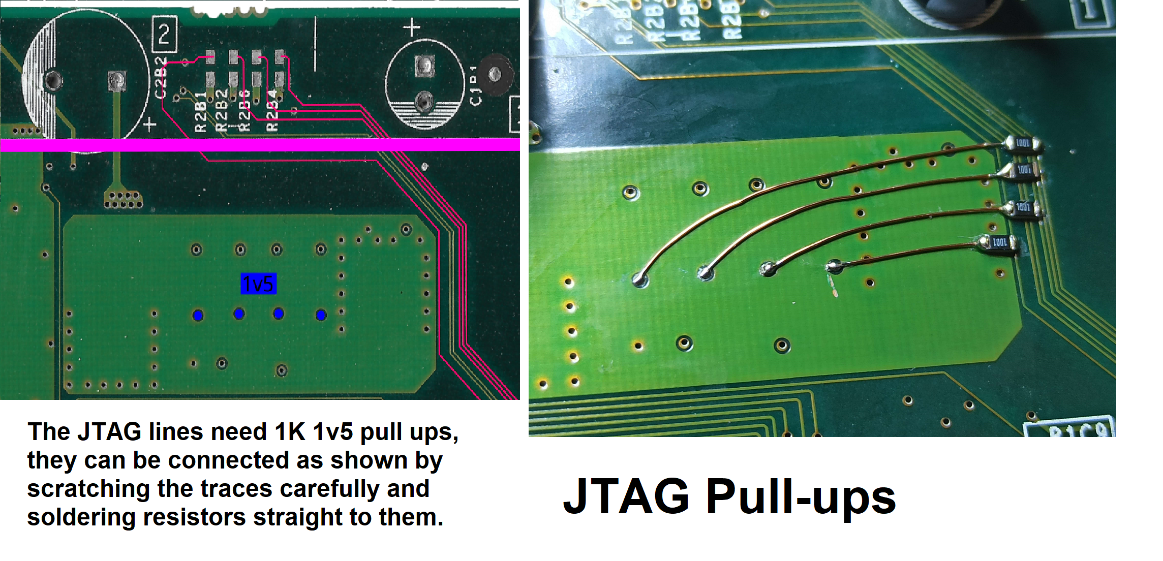
Additionally both the power and eject switch lines need pull up resistors in order for the Xbox to boot normally, and the CPU JTAG lines need 1K pull ups to 1v5. They are shown in separate diagrams.
THANK YOU:
I would like to thank a few people that helped make this possible, and they are as follows:
YveltalGriffin: Help with figuring out the Xbox I2S audio timings, advice on various PCBs in the portable which all of this was for, and just for always being helpful.
LoveMHz and Gaasedelen: Help with figuring out some of the inner workings of the Xbox when I was mapping it all out, and LoveMHz supplying scans for some of the materials used in the guide.
Ernegien: Help with understanding USB and termination for such when I was being dumb.
If I left anyone off it's only cause I am forgetful, you know I appreciate you.
Thanks!
I have put a lot of time and effort into this guide and there were a LOT of ups and downs, but I hope it is worth it as at the end of the day it shows you everything you need to know to do something that was anecdotally impossible for years, and that is pretty darn cool.
DISCLAIMER:
As always there is risk involved in doing any project like this. Follow along at your own risk.
Additionally there are 3 retail Xbox motherboards. This guide is only for the 3rd and final board revision, X01063-121 or 121 for short. The 2 older PCBs are not suitable for portable use, they cannot be cut down as densely (or at all), and they draw up to 50% more power, and they lack a variety of hardware that amounts to making the 121 board perfect for the job. All research and documents pertain to the 121 board, and this is what is detailed in the Compendium document as well.
The following is the "anatomy" of the 121 motherboard, please get acquainted with it before proceeding.
USB RELOCATION:
USB is used by the Xbox for controllers, and memory cards, and is a necessary relocation for proper function of the Xbox.
If each lane is not terminated, some BIOS and pieces of software can freeze, crash or in some cases not detect controllers. (Even if you terminate the lane you are using, if the others aren't terminated this can occur.)
Below you can find a diagram detailing USB via "pinout" as well as how to terminate each port.
XCALIBUR REBUILD:
The Xcalibur chip is a custom video encoder that also handles tasks such as monitoring the CPU temp and reporting to the SMC when an overheat occurs.
It is at this time required for the Xbox to even boot. For the basic trim in this guide some vias are severed, so it will need some pins reconnected and rebuilt.
I2S AUDIO:
The Xbox MCPX outputs 2 types of digital audio, SPDIF, and AC97. SPDIF is routed straight to the AV output port for some AV output modes, and the AC97 is converted for analog audio.
On previous boards there is a dedicated AC97 DAC for this job, however the 121 uses the custom Xyclops SMC to convert AC97 to I2S, which then goes to a cheaper I2S DAC.
Thanks to this we can very easily use crisp digital audio in our portables.
It is possible to use the U-AMP2 to do this, however it isn't implemented just yet.
IDE RELOCATION:
IDE is used for the DVD and HDD drive connections in a stock unmodified Xbox.
It is currently the only means of attaching storage to the Xbox, as such it is a required relocation for an Xbox portable.
An Xbox will boot without storage but only as far as the boot animation and a subsequent error screen. (So you can test a trim without, but not really use it)
The DVD drive is similarly a requirement for a stock BIOS, so a modified BIOS that patches it out is required to bypass an error screen.
The IDE relocation is sorta involved without a flex but it is totally doable with or without one.
The following diagram will tell you everything you need to know.
AV MODE:
The video output signal/type is set based on the state of 3 pins on the Xyclops SMC.
The following diagram is far from comprehensive as far as what all modes it can do, but it should be sufficient for portable use.
If no mode is set, the Xbox will fail to boot and flash the LED orange and green, so you must have at least some AV mode set.
STANDBY REMOVAL:
In order to boot the Xbox without the stock regulators or PSU (Additionally because a continuous ~30mA draw isn't ideal for a portable device), we must remove the need for standby voltage.
While it didn't seem like it at the time while researching, it is relatively straight forward. It is recommended to do this mod and test it before you trim. (The PSU will need to be jumpered on)
TRIMMING:
Before trimming it is recommended that you have a standby voltage free hardmodded (With a no-DVD BIOS) motherboard that is tested and working.
You should tape off at least the BGA chips, but preferably the whole area inside the trim line to save on conductive dust clean up later.
Use the following diagrams to mark out your trimline, and then cut slightly outside the line with a Dremel and a diamond cutting wheel, and then sand your way in to prevent damage to anything important.
Once trimmed you will need to sand the edges at an angle to separate the 4 copper layers of the PCB and remove/prevent shorts. It is recommended to work your way up to at least 600 grit in increasing increments.
During this process you should keep checking the various voltage rails for shorts with a multimeter in resistance mode, "continuity" mode is not sensitive enough for this and will give false positives.
A rough number for what resistance each rail should be is as follows:
* 1v375: 10Ω
* 1v5: 70Ω
* 1v725: 40Ω
* 2v65: 28Ω
* 3v3: 35Ω
* 5v: 3MΩ
(Most auto ranging meters won't be able pin down 5v resistance because it is so high, so just make sure it is above 0Ω.)
It will vary from board to board by some amount but the important thing is that they are close and even more so that they are above 0Ω.
REWIRING:
When the board is trimmed a handful of connections are severed, these are required for the Xbox to boot and as such must be reconnected prior to using the trim.
Additionally both the power and eject switch lines need pull up resistors in order for the Xbox to boot normally, and the CPU JTAG lines need 1K pull ups to 1v5. They are shown in separate diagrams.
THANK YOU:
I would like to thank a few people that helped make this possible, and they are as follows:
YveltalGriffin: Help with figuring out the Xbox I2S audio timings, advice on various PCBs in the portable which all of this was for, and just for always being helpful.
LoveMHz and Gaasedelen: Help with figuring out some of the inner workings of the Xbox when I was mapping it all out, and LoveMHz supplying scans for some of the materials used in the guide.
Ernegien: Help with understanding USB and termination for such when I was being dumb.
If I left anyone off it's only cause I am forgetful, you know I appreciate you.
Thanks!
Attachments
-
 3 MB Views: 23
 -
 2.8 MB Views: 20
 -
 3.8 MB Views: 22
 -
42.7 MB Views: 20
-
 24.6 MB Views: 17
 -
 10.4 MB Views: 27
Last edited: