hi guys here are the two and (I think) latest updates from yesterday and today:
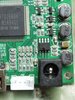
yesterday I started with the controller board swap with the new xenii designer (installed on his V3)
Currently I haven't tried it thoroughly compared to the old one (over 30 hours of use and using it the keys started working at the slightest touch) with this one they are immediately responsive so I imagine it can only still improve but they are already perfect as they are!
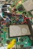
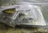
the second and significant update consists in eliminating the VGA and installing the fuji flex (poor man variant with no money lol):
why "poor man variant with no money"?
like other things (example xii flex and controller board with hasal and not gold) ,
there were these variations:
- flex always strictly 0.11mm instead of 0.12mm
- normal SOP8 eeprom instead of the smd one for availability (25p40)
- as above, the integrated circuit that generates 1.8v at 1.2... I wanted to use an ams1117 but then I remembered that the pms generates 1.15v... I read the fpga datasheet and I calmly read that the minimum voltage is 1v so..... integrated bypassed by a 0ohm resistor and the 1.8v pad connected to 1.15v of the pms
- various components recovered from ko PC boards - remaining boards for this project, even the flex connectors are different and the ground connection has been modified. Since the PCB is very thin, reinforcements were installed near the flex and the ground directly on the board

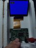
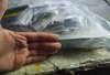
Let's say goodbye to the now disconnected and useless VGA cables... the next challenge was that I thought too late that the Fuji Flex was in conflict with the Xii Flex! so I had to solder two flexes on the motherboard which was practically crazy... the only solution to not go crazy and be sure of success was to cut the xii flex on the side so that the pads were in contact with the external edge, once this was done move it slightly back compared to the fujiflex pads and solder everything... easy, right?
I thought the two systems were in conflict and instead they work! , the screen seems ok even as margins compared to VGA seem unchanged
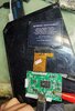
the nice and positive thing is that now if it needs to be dismantled the screen and the back can be separated without problems and without cables! (xii approved lol) only I didn't know where to take the 5v and I didn't like the cable that went from the fuji to the controller board, but I didn't even want to remove the motherboard.... fortunately there is a bit of space on the side of the PCB with the power lines, I pass the cable with targeted welding and there it is, our 5v in position and perfectly hidden
I would say at the moment the project is completely finished, I also chose the external eeprom for ease of updating if another fw comes out, it would be nice to have an fw that allows the pic controller to modify the gcvideo menu or a method


")