Plying Trac!! Isn't life just a barrel of monkeys!!!
Well we all know this to be true, and we also know that the urge to suddenly resume a project that you didn't even realize you'd stopped working on, (I don't understand it either) hits you like several kilograms of hurled cellulite... After you see @Mister M 's latest update.
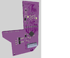
So here you go, some rather large images taken from the 3d render suite:
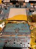
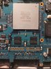
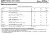
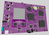
Motherboard front and back
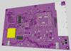
HDD adapter, now using an M.2 SATA III drive, and incorporating the Memory Card slot 1 port
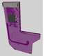
Thanks to this guy for the M.2 idea:
Right then, now for the explanations, and queries lol.
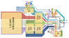
So as you can see, lot's of progress, lot's of changes. First and foremost, I'm not even going to attempt to make my own video converter. For this reason, the large patch of silk screen on the back of the main board is where I will place a lovely little Gem... a RetoGem to be precise! This will also give me the ability to use the 7 inch 1920x1200 MIPI LCD I have... So we'll see what happens, but hopefully it works!! They're kind enough to include a lot of pinouts and info, so it feels like a match made in Heaven.
You may have also noticed the large yellow square on the back of the board, which is going to be where the modchip goes. The Memory Card containing FMCB, and the controller IC however, are fully integrated.
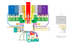
Anyway, what I'm working on right now is the power domains. Texas Instrument's BQ40Z50RSMR-R should make for a good Battery circuit, and I've been thinking of using the TLV62130 for some of the higher current domains, like the 1.2 volt. Then maybe a few TPS628511 for the lower current ones.
Which brings me to the first of my queries; How do I determine how much current each domain needs, and thus which specific regulator to use in terms of output? Given the heavy use of linear regulators in the earlier PS2 designs, I'm guessing the current requirements shown in the 70000 service manual are probably already geared toward the higher degree of loss. So, should I maybe just use a multimeter to see how much current is on each domain during heavy load (playing a game)? Do Buck Converters only output as much current as their load's are asking for? Are they like electrical Chakra pools?

Another query related to power; the CON 3.4 Volt rail, and the DIG 3.5 Volt rail, would seem to be fed by the same regulator, separated only by a 2 amp fuse, and a zero Ω resistor (bridge). The multimeter even says they're the same, so can I just let them be the same domain? Like merge the nets for CON 3.4 and DIG 3.5?
Honestly, some of the design choices they made back then...
Anyway, I hope everyone is well!!
Happy tinkering my Dudes!!
Well we all know this to be true, and we also know that the urge to suddenly resume a project that you didn't even realize you'd stopped working on, (I don't understand it either) hits you like several kilograms of hurled cellulite... After you see @Mister M 's latest update.
So here you go, some rather large images taken from the 3d render suite:
Motherboard front and back
HDD adapter, now using an M.2 SATA III drive, and incorporating the Memory Card slot 1 port
Thanks to this guy for the M.2 idea:
Right then, now for the explanations, and queries lol.
So as you can see, lot's of progress, lot's of changes. First and foremost, I'm not even going to attempt to make my own video converter. For this reason, the large patch of silk screen on the back of the main board is where I will place a lovely little Gem... a RetoGem to be precise! This will also give me the ability to use the 7 inch 1920x1200 MIPI LCD I have... So we'll see what happens, but hopefully it works!! They're kind enough to include a lot of pinouts and info, so it feels like a match made in Heaven.
You may have also noticed the large yellow square on the back of the board, which is going to be where the modchip goes. The Memory Card containing FMCB, and the controller IC however, are fully integrated.
Anyway, what I'm working on right now is the power domains. Texas Instrument's BQ40Z50RSMR-R should make for a good Battery circuit, and I've been thinking of using the TLV62130 for some of the higher current domains, like the 1.2 volt. Then maybe a few TPS628511 for the lower current ones.
Which brings me to the first of my queries; How do I determine how much current each domain needs, and thus which specific regulator to use in terms of output? Given the heavy use of linear regulators in the earlier PS2 designs, I'm guessing the current requirements shown in the 70000 service manual are probably already geared toward the higher degree of loss. So, should I maybe just use a multimeter to see how much current is on each domain during heavy load (playing a game)? Do Buck Converters only output as much current as their load's are asking for? Are they like electrical Chakra pools?
Another query related to power; the CON 3.4 Volt rail, and the DIG 3.5 Volt rail, would seem to be fed by the same regulator, separated only by a 2 amp fuse, and a zero Ω resistor (bridge). The multimeter even says they're the same, so can I just let them be the same domain? Like merge the nets for CON 3.4 and DIG 3.5?
Honestly, some of the design choices they made back then...
Anyway, I hope everyone is well!!
Happy tinkering my Dudes!!
Last edited: