Another OMGWTF Troubleshooting Thread

Joined
Feb 16, 2023
Messages
21
Likes
24
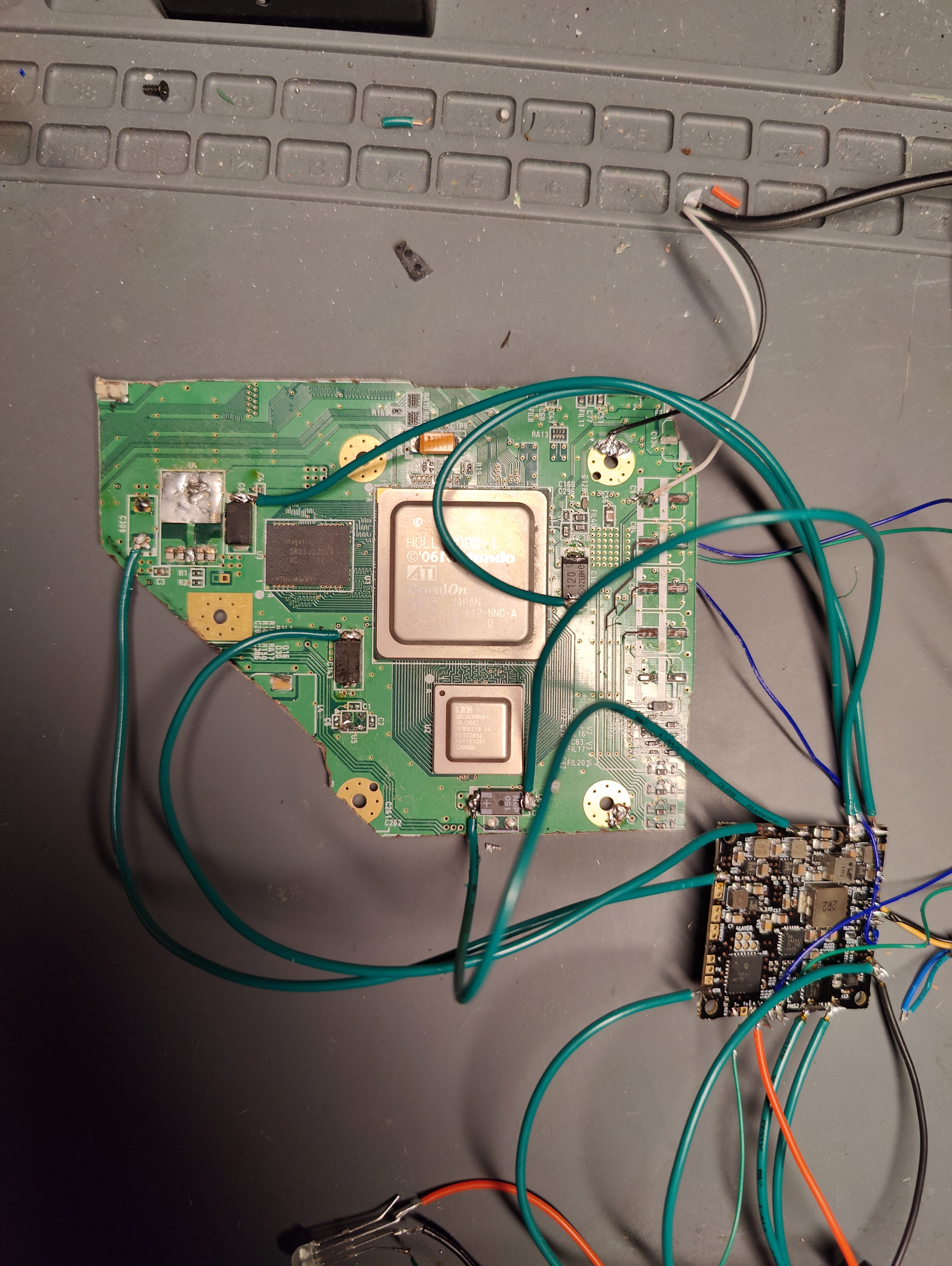
Evening, all. So I did the OMGWTF trim on a 4 layer board and tried to reference several videos to try and get it as accurate as I could. I also got an RVL-PMS-2 and attempted to wire everything together (after doing the U10 relocation because I apparently can't read) and am not getting anything.

I made sure to sand the edges using the appropriate grits as well as check all the resistances and everything checked out. I get nothing when I give the PMS power and I've tried soldering things in several different places based on different guides and videos I could find with no luck.

Any ideas on something obvious I might be missing? (If any soldering looks gross, it's on purpose because I was hoping to do a quick-and-dirty test to verify the trim was successful before I dumped a bunch of time into other things like designing my case/etc.)


Here are my SCW, SDW, and U10 connections (the seem solid. I pulled on them and they didn't budge, but I taped them anyway just in case):

IMG20230609183103.jpg


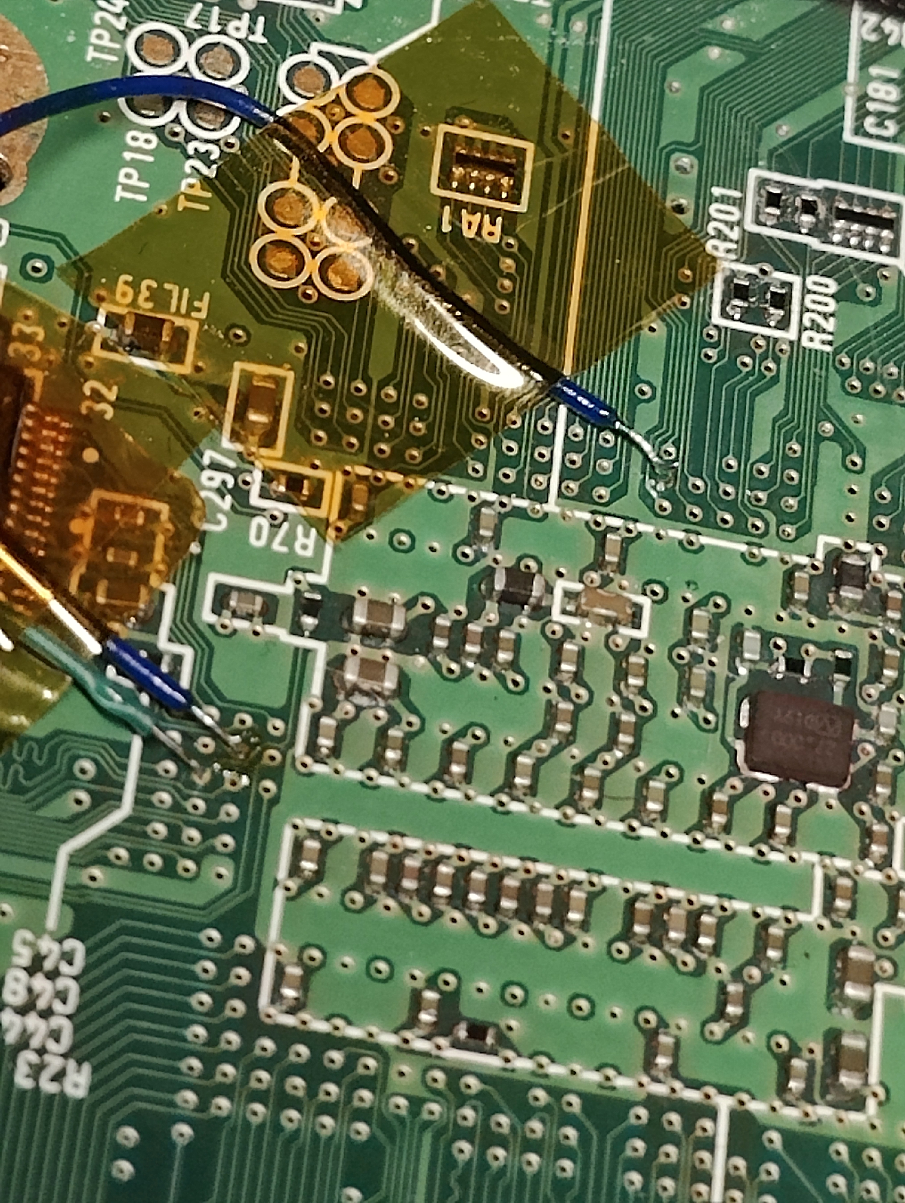
Sorry everything is green. It's the only 22awg I had on hand lol
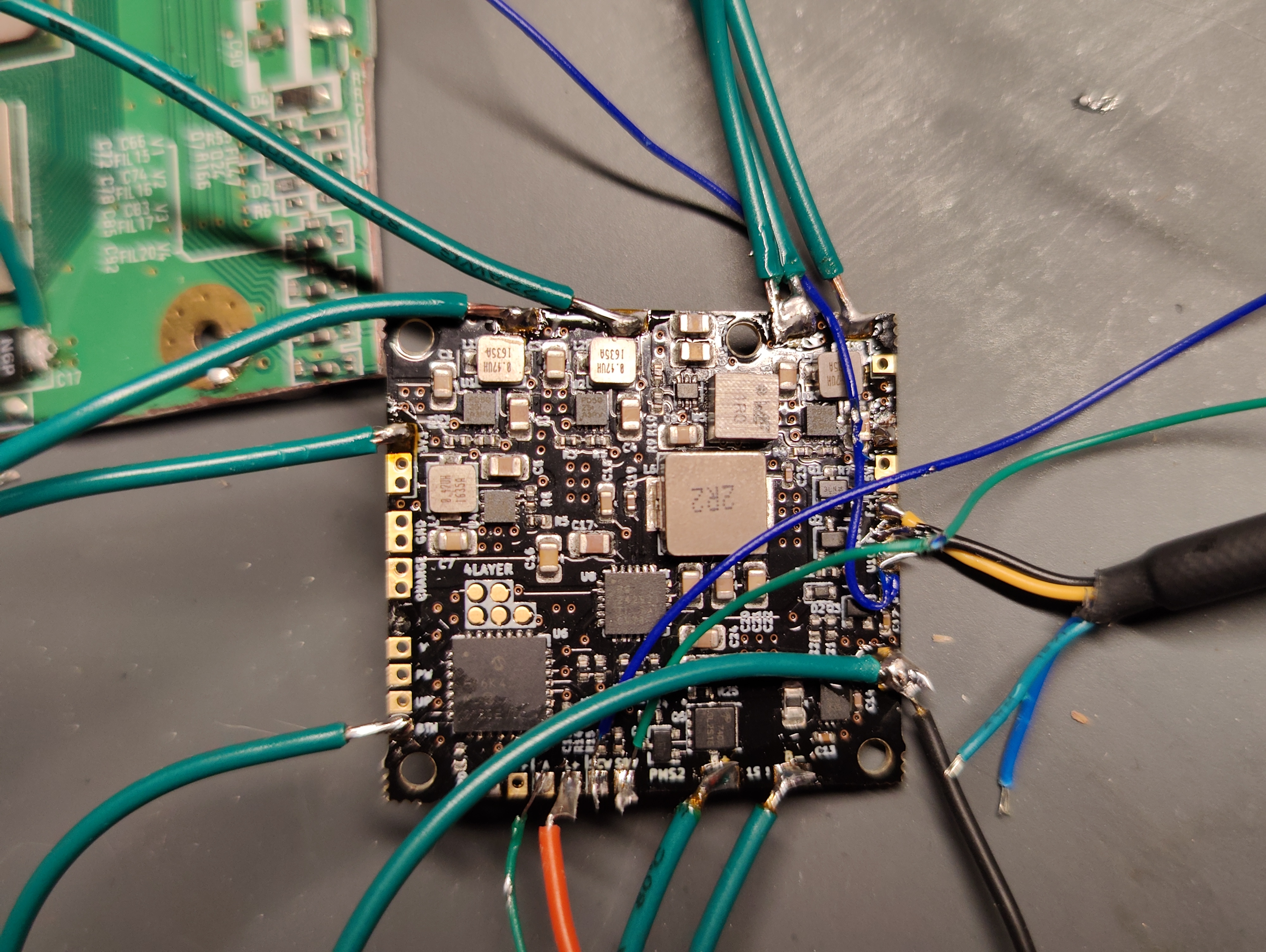
IMG20230609195412.jpg


The PMS 2:
IMG20230609195450.jpg


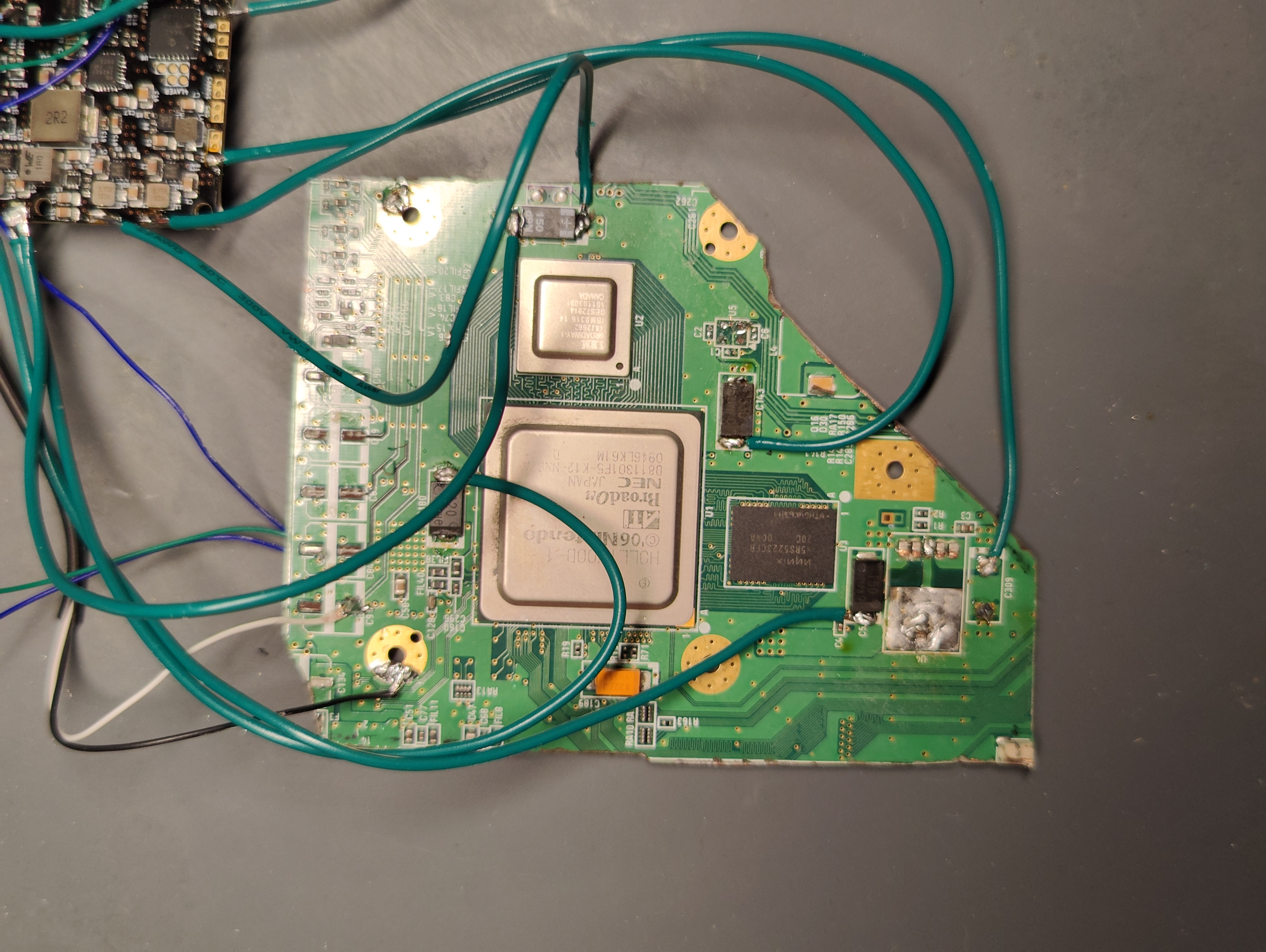
Slightly better picture of the overall trim:
IMG20230609195550.jpg
 
Last edited:

Stitches

2 and a Half Dollarydoos
Staff member
.
.
Joined
Feb 5, 2017
Messages
3,853
Likes
3,026
Location
Banana Bender Land, Australia
Portables
6
When you say you gave the PMS power, did you connect a charge voltage or did you wire in lithium cells to the battery pads?

Also, the overexposed wires are giving me hives. There's a hundred potential shorts there
 

CrazyGadget

Crazy Helpful, CrazyGadget
.
Joined
Jun 6, 2020
Messages
612
Likes
882
Location
Downing's Closet
Portables
???
  • Those edges look rough. What grits did you use, and what's your resistances chart looking like? It would be good to get a second set of eyes on all of that.
    • It would be best to try to smooth out the sides that have a couple gouges in them, if possible. It's hard to sand in gouges like that and make way for shorts between the layers.
  • Those solder joints are also very rough. You have too much bare wire exposed on all of the wires, which leaves a lot of opportunity for bridging.
    • They also look very cold, with the solder not covering the entire pad, and like the wires were not properly tinned.
    • I would recommend practicing your soldering on the remains from the trim until you feel more comfortable getting solid connections.
  • SCW and SDW are not necessary to see boot.
  • Your composite line is on the wrong side of where the DC blocking cap was, but it looks like the other pad got ripped off. Solder to the composite via on the other side of the board, marked in the Definitive Wii Trimming Guide.
I hope this helps!
 
Joined
Feb 16, 2023
Messages
21
Likes
24
When you say you gave the PMS power, did you connect a charge voltage or did you wire in lithium cells to the battery pads?

Also, the overexposed wires are giving me hives. There's a hundred potential shorts there
Bench power supply. Tried several different voltages based on what I could find in the forums. Specifically 3.7 and 4.2.

Yeah I tried to make sure the wires didn't bridge and didn't catch anything odd with continuity but it probably wouldn't hurt to just do a better job and rule that out lol
 
Joined
Feb 16, 2023
Messages
21
Likes
24
  • Those edges look rough. What grits did you use, and what's your resistances chart looking like? It would be good to get a second set of eyes on all of that.
    • It would be best to try to smooth out the sides that have a couple gouges in them, if possible. It's hard to sand in gouges like that and make way for shorts between the layers.
  • Those solder joints are also very rough. You have too much bare wire exposed on all of the wires, which leaves a lot of opportunity for bridging.
    • They also look very cold, with the solder not covering the entire pad, and like the wires were not properly tinned.
    • I would recommend practicing your soldering on the remains from the trim until you feel more comfortable getting solid connections.
  • SCW and SDW are not necessary to see boot.
  • Your composite line is on the wrong side of where the DC blocking cap was, but it looks like the other pad got ripped off. Solder to the composite via on the other side of the board, marked in the Definitive Wii Trimming Guide.
I hope this helps!
All good suggestions!

As for grits, I did 80, 100, 200, 400, and 1000. But I should probably go back and clean up the gouges and give it another pass to rule that out.

Resistances were almost all perfect and the only times they were off, they were higher than what was listed (which from what I've found on some other forum posts from Wesk seems to indicate it should be fine). But I'll go through and make a formal chart once I clean things up.

Solder joints are admittedly pretty bad as I was hoping for a "good enough" job to verify it worked and then was gonna make it cleaner. But I think I just need to invest the time in planning out the layout I want and doing a better job just to rule out any possible weirdness with bridging.

For the composite, I tried on both sides (with the caps and without) but didn't have any luck (probably due to other issues) but I'll be sure to relocate that as well.

Thanks for the tips!
 

Stitches

2 and a Half Dollarydoos
Staff member
.
.
Joined
Feb 5, 2017
Messages
3,853
Likes
3,026
Location
Banana Bender Land, Australia
Portables
6
Bench power supply. Tried several different voltages based on what I could find in the forums. Specifically 3.7 and 4.2.

Yeah I tried to make sure the wires didn't bridge and didn't catch anything odd with continuity but it probably wouldn't hurt to just do a better job and rule that out lol
I've seen a few people now say they used a bench supply with no luck. I wonder if the PMS doesn't like the fixed voltage...........
 
Joined
Feb 16, 2023
Messages
21
Likes
24
I've seen a few people now say they used a bench supply with no luck. I wonder if the PMS doesn't like the fixed voltage...........
Oh really? That's a new one for me.

I've got some 18650s lying around. I'll top those off and give it a shot once I clean up everything. Thanks for the idea of another thing to test!
 
Joined
Feb 16, 2023
Messages
21
Likes
24
Alright @Stitches and @CrazyGadget, Round 2 lol Redid everything and am still not seeing anything (no light, no fan, or video)

Here are the resistance values with nothing attached to the board as well as a similar board and values:
resistances.png


Here are some of the freshly sanded edges.
IMG20230609233537.jpg

IMG20230609233551.jpg


Next is the composite stuff moved to the other side of the board:

IMG20230611165051.jpg


Finally, all of the connections and redone solder joints. I tried several different temperatures between 370 and 400C just to try them out. But hopefully the closer lengths helps your hives, @Stitches lol
IMG20230611164729.jpg

IMG20230611164708.jpg
 
Joined
Feb 16, 2023
Messages
21
Likes
24
Small development, the TV registers that I'm getting a signal, but the screen is black. So that gives me something to start googling at least
 

CrazyGadget

Crazy Helpful, CrazyGadget
.
Joined
Jun 6, 2020
Messages
612
Likes
882
Location
Downing's Closet
Portables
???
Looking better! When you turn on the PMS, are all of the output voltages correct? And is your U10 line still solid?
 
Joined
Feb 16, 2023
Messages
21
Likes
24
Looking better! When you turn on the PMS, are all of the output voltages correct? And is your U10 line still solid?
All voltages are reading perfect and the U10 still feels solid

I did dig around the forum a little and saw a comment on someone else's worklog about the composite cable possibly being too long? Mine is like 3 feet lol would that be causing any attenuation issues?
 

Stitches

2 and a Half Dollarydoos
Staff member
.
.
Joined
Feb 5, 2017
Messages
3,853
Likes
3,026
Location
Banana Bender Land, Australia
Portables
6
Now that looks heaps better! I'd clean off this clump of burnt stuff on the edge of the trim tho.
1686532904509.png

Carbonised burnt stuff can cause transient shorts
 
Joined
Feb 16, 2023
Messages
21
Likes
24
Thanks!

Now that looks heaps better! I'd clean off this clump of burnt stuff on the edge of the trim tho.
View attachment 28075
Carbonised burnt stuff can cause transient shorts
Not a bad idea. I'll go through and give it a more thorough clean.

I did manage to get it to run with a bench power supply, by the way! Again, it registers a signal but it's just a black screen.

I'll be on to work on it in a bit
 
Joined
Feb 16, 2023
Messages
21
Likes
24
Trimmed the cable to like 6-7" and still no video so that ain't it. More digging required!
 

Stitches

2 and a Half Dollarydoos
Staff member
.
.
Joined
Feb 5, 2017
Messages
3,853
Likes
3,026
Location
Banana Bender Land, Australia
Portables
6
Also it looks like you might have hit C47. Should probably remove those passives on the edge there
1686546223190.png

Got a picture of the back side of the Wii?

Having spent a few hours digging through forum posts (and subsequently finding a lot of your comments) I can say that you're pretty good at spotting those lol

But alas, after cleaning it up, no dice.

Gonna reflow some stuff and see if that magically works
I worked as a handyman for like 7 years and learned to do everything from painting and locksmithing to deck building and tree lopping. When half your job is fixing mistakes left behind by the last cheap jackass hired to do a job, it trains your eye to spot imperfections rather quickly
 
Last edited:
Joined
Feb 16, 2023
Messages
21
Likes
24
Also it looks like you might have hit C47. Should probably remove those passives on the edge there
View attachment 28087
Got a picture of the back side of the Wii?


I worked as a handyman for like 7 years and learned to do everything from painting and locksmithing to deck building and tree lopping. When half your job is fixing mistakes left behind by the last cheap jackass hired to do a job, it trains your eye to spot imperfections rather quickly
Good catch. Removing now.

And yeah I can see how that much experience would bleed over and be super helpful.

Not sure what changed but before, I needed to press the button to turn on the PMS but now it's starting up as soon as I give it power. So either something is bridged (which I redid everything and double-checked it so I'm pretty sure it's not that) or something internally has broken and part of the PMS may be dead lol Time to start probing
 
Joined
Feb 16, 2023
Messages
21
Likes
24
Also it looks like you might have hit C47. Should probably remove those passives on the edge there
View attachment 28087
Got a picture of the back side of the Wii?


I worked as a handyman for like 7 years and learned to do everything from painting and locksmithing to deck building and tree lopping. When half your job is fixing mistakes left behind by the last cheap jackass hired to do a job, it trains your eye to spot imperfections rather quickly
As requested:

IMG20230612001437.jpg
 
Joined
Feb 16, 2023
Messages
21
Likes
24
Good catch. Removing now.

And yeah I can see how that much experience would bleed over and be super helpful.

Not sure what changed but before, I needed to press the button to turn on the PMS but now it's starting up as soon as I give it power. So either something is bridged (which I redid everything and double-checked it so I'm pretty sure it's not that) or something internally has broken and part of the PMS may be dead lol Time to start probing
Just confirmed that I'm getting continuity between PWR and GND :( Not sure how that happened as I've kept all the contacts away from each other and didn't have any bridging, but that pretty much confirms it's dead and I'll need to replace the battery management circuits
 
Top