Worklog Ashida First Portable Worklog

Joined
Mar 20, 2023
Messages
18
Likes
8
Location
United States, Kansas
Hello! I'm so excited to finally start this worklog, and in turn, this project. I'm building an Ashida and I've recieved a lot of my parts. Most of you know the specs, so I won't go into them, but I will talk about some goals with this.

I want to do these things:
  • Wifi Relocation
  • Bluetooth Relocation
  • MX Chip Relocation
So basically all the relocations. I mainly want to do them all so that I get some practice with them if I ever need to add them to a future build. I can live without the MX Chip, but I would really love both bluetooth and wifi.

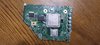
An additional thanks to @CrazyGadget for his Driver Board. It allows me to keep all the buttons assigned to their intentional spots while still being able to easily access the screen's menu.

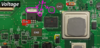
I've disassembled the Wii and I'm about to draw the outline to trim it. As I'm doing the Ashida build, it will be an OMGWTF trim. And man is it tiny. I'll post pictures of my setup and Wii with the outline after I get it all set up. I just wanted to post this to get the whole worklog process started. The goal of today is to get it trimmed and sanded, while possibly doing the relocations today. The only issue is that I need Kapton tape and it isn't here yet and I want to start the trimming process, so I'm gonna just hope I can do the relocations. If I mess up on any (but hopefully not all) it shouldn't be a big deal, but I will definitely be heartbroken.

Anyways, that's the introduction. I'll be back shortly to post my trim outline and possibly double check if it it won't destroy my Wii, but I'm gonna cut far outside the line and give myself a lot of room for error.
 
Last edited:
Joined
Mar 20, 2023
Messages
18
Likes
8
Location
United States, Kansas
Here's my outline. I tried to be very cautious with my line. I'm still gonna cut outside of it, and hopefully it'll be all okay. If anyone is quick enough, could you double check this? I think as long as I'm cautious, this will be okay. I just want to be as careful as I can.

Thanks everyone!

EDIT: I'm also gonna put tape all on the inside of the outline, that'll help me too!
 

Attachments

Joined
Feb 12, 2023
Messages
9
Likes
20
Location
CA
Portables
1
Trim lines look good! Tape on the inside of the outline is also a good idea - particularly on top of the main chips/nand to make sure nothing gets underneath during the cut and causes a short later. I used masking tape for this, and didn't use kapton tape until actually doing electronic connections/wire routing.

For any large components the trim line passes through (like the capacitors bottom-center and top-right) I would remove before you start trimming. Anything surface mounted that gets cut through should be desoldered after the trim.

Best of luck!
 

Stitches

2 and a Half Dollarydoos
Staff member
.
.
Joined
Feb 5, 2017
Messages
3,857
Likes
3,027
Location
Banana Bender Land, Australia
Portables
6
Also, it's helpful to cut off entire lengths of the PCB, rather than trying to cut the trim section out of the middle like surgery. Example:
1680479131251.png

The first cut line takes off nearly half of the PCB, reducing the weight and giving you an easy entrance to cuts 2 and 3. If you like you can flip cuts 3 and 4 around and do cut 4 first to square the trim off, then do cut 3 afterwards
 

Stitches

2 and a Half Dollarydoos
Staff member
.
.
Joined
Feb 5, 2017
Messages
3,857
Likes
3,027
Location
Banana Bender Land, Australia
Portables
6
Thanks guys, I'll definitely keep that in mind. Side question: What's the downside to having a cpu-40 compared to a cpu-60?
No downsides AFAIK, and there's no measurable performance difference between revisions. Board revisions after the CPU-40 were mainly to adjust for part availability and a few hardware exploit fixes, which doesn't affect our use case since we trim off all the non-essential stuff and use IOS patches.
 

Bozer

.
Joined
Mar 31, 2022
Messages
43
Likes
14
you should be fine, all of the NAND lines are intact so ur good. Just make sure to sand it good of course, and make sure you desolder any components you cut through
 
Joined
Mar 20, 2023
Messages
18
Likes
8
Location
United States, Kansas
MX Chip cut!
IMG_20230402_214403353.jpgIMG_20230402_214409477.jpg

I ordered all the sandpaper on Amazon and now I'm waiting till Tuesday for it to arrive. Soon I'll be getting the Ashida PCBs, GC+, and U-amp 2 and I'll solder all of those together.

Thanks for your help guys!
 

Stitches

2 and a Half Dollarydoos
Staff member
.
.
Joined
Feb 5, 2017
Messages
3,857
Likes
3,027
Location
Banana Bender Land, Australia
Portables
6
Looks good. You have some good room to sand before you hit anything vital.
1680492924085.png

Just make sure you don't sand past these red lines, or you'll hit the NAND traces
 
Joined
Mar 20, 2023
Messages
18
Likes
8
Location
United States, Kansas
Hey guys I got a quick question: I know I sand at an angle with each grit listed on the Wii trimming guide, but how long should I sand for each individual grit?

Also, I got my GameCube controller in and I'm gonna desolder the needed parts, do I use the blob method like on the U10? I don't have a hot air station here, but I have a family member that has one, so if it's absolutely necessary I can get to one.

Thanks guys!
 
Joined
Nov 25, 2022
Messages
89
Likes
14
Portables
1
Hey guys I got a quick question: I know I sand at an angle with each grit listed on the Wii trimming guide, but how long should I sand for each individual grit?

Also, I got my GameCube controller in and I'm gonna desolder the needed parts, do I use the blob method like on the U10? I don't have a hot air station here, but I have a family member that has one, so if it's absolutely necessary I can get to one.

Thanks guys!
i used a solder sucker and it worked great. I don’t think a blob method would work on a lot of the parts unless you have that de soldering solder that stays hot really long. But a solder sucker or solder wick will help with the controller parts

srry idk ab the time needed to sand - im sure someone will respond here soon
 
Joined
Mar 20, 2023
Messages
18
Likes
8
Location
United States, Kansas
Oh yeah duh, thanks I should've known that. I asked before I actually looked at the controller. What temp do you recommend to desolder at? Thanks for you help!

Edit (Additional Question): Where is the 1.8v at on the wii motherboard? I'm measuring my resistances before I sand it to see the change, but I can't find the 1.8v on the Definitive Wii Trim Guide. Thanks again!
 
Last edited:
Joined
Nov 25, 2022
Messages
89
Likes
14
Portables
1
No problem homie or homet, here is a picture of 1.8 lines that stitches gave me. You would desolder at the same temp you solder or maybe a little bit more depending on your method.

Check this vid on desoldering -
 

Attachments

Stitches

2 and a Half Dollarydoos
Staff member
.
.
Joined
Feb 5, 2017
Messages
3,857
Likes
3,027
Location
Banana Bender Land, Australia
Portables
6
Hey guys I got a quick question: I know I sand at an angle with each grit listed on the Wii trimming guide, but how long should I sand for each individual grit?

Also, I got my GameCube controller in and I'm gonna desolder the needed parts, do I use the blob method like on the U10? I don't have a hot air station here, but I have a family member that has one, so if it's absolutely necessary I can get to one.

Thanks guys!
If you have the sandpaper on the table and you're rubbing the PCB against it with minor downward pressure, maybe 5-10-ish seconds per side per grit? You just need to get the layer flakes off, so don't go too hard on it. Your trim has plenty of margin, but it can evaporate quickly with the lower grits

Oh yeah duh, thanks I should've known that. I asked before I actually looked at the controller. What temp do you recommend to desolder at? Thanks for you help!

Edit (Additional Question): Where is the 1.8v at on the wii motherboard? I'm measuring my resistances before I sand it to see the change, but I can't find the 1.8v on the Definitive Wii Trim Guide. Thanks again!
Most consumer electronics use lead free solder, so I find an iron temp of around 380 degrees C to be enough for that. If using hot air, I'd go for a flat 400C
 
Joined
Mar 20, 2023
Messages
18
Likes
8
Location
United States, Kansas
Thank you everyone! I've desoldered the two stick boxes and tommorrow I'll desolder the analog sliders for the L and R buttons.

Also, I've sanded my Wii and recorded the resistances. Do these look okay? All looks okay except the resistance between the 3.3v pins to everything else is roughly 2kΩ less than Nold's. I assume this is just variations between Wiis (and the fact we're cutting them in half). Am I right in that assumption?

1680669625361.png


Thanks!
 

Stitches

2 and a Half Dollarydoos
Staff member
.
.
Joined
Feb 5, 2017
Messages
3,857
Likes
3,027
Location
Banana Bender Land, Australia
Portables
6
There will always be some variance between trims and board revisions. Your numbers look okay to me
 
Joined
Mar 20, 2023
Messages
18
Likes
8
Location
United States, Kansas
Hey guys, I'll be getting my 4layer boards in today and I'm gonna try to boot the Wii. As of right now, the PMS-PD is out of stock. I know I'll probably need to be charging the batteries and I was wondering if there was a safe way to do that without the PD.

Thanks again!
 

Stitches

2 and a Half Dollarydoos
Staff member
.
.
Joined
Feb 5, 2017
Messages
3,857
Likes
3,027
Location
Banana Bender Land, Australia
Portables
6
Hey guys, I'll be getting my 4layer boards in today and I'm gonna try to boot the Wii. As of right now, the PMS-PD is out of stock. I know I'll probably need to be charging the batteries and I was wondering if there was a safe way to do that without the PD.

Thanks again!
IIRC the PMS accepts 5v to 15v charging input. A 3 amp 9v or 12v supply would probably be easiest
 
Joined
Mar 20, 2023
Messages
18
Likes
8
Location
United States, Kansas
Okay! I've done a lot of progress today! I soldered on the U AMP 2 board along with the GC+2.0. Then I soldered on the stick boxes and shoulder button pots. Lastly I finished up the peripherals on the Ashida boards.

GC+2
IMG_20230415_141442414.jpg
IMG_20230415_141449709.jpg

Shoulder Pot
IMG_20230415_141456352_HDR.jpg
C-Stick Box
IMG_20230415_141506008.jpg
UAMP-2
IMG_20230415_141514122.jpg
IMG_20230415_141522436.jpg
Extra Peripherals
IMG_20230415_141528484.jpg
IMG_20230415_141533861.jpg
IMG_20230415_141540208.jpg
Left Analog Stick Box
IMG_20230415_141545967_HDR.jpg
Left Shoulder Pot
IMG_20230415_141552123_HDR.jpg


I think now I'll move onto the PMS-2 and see if I can turn on the Wii. Any suggestions or help for how to do that with minimal risk of damage?

EDIT: I understand that the PMS has the U10 emulation, and that all the regulators should be in that board as well. WiFi is patched out, along with Bluetooth not being necessary. Then I should be able to connect the screen to the Wii with composite? Even if I have the VGA patch? I unplug and plug it back in correct? Would that be all I'm looking to do?

For the voltage regulator, am I just straight up connecting the PMS 2 to the Wii? And keep what's left of the regulators on the Wii itself?
 
Last edited:
Top