Worklog Ashida Worklog

Joined
Jun 8, 2022
Messages
7
Likes
7
Location
Banana Hoard
Portables
Ashida (WIP)
Hey all! I've started working on my Ashida and have had some questions, so I figured I'd make a worklog in case someone has the same questions as me. I'm not new to soldering, but I'm also not exactly an expert at it, especially for projects like this. I mostly just mod simple functional mods for gamecube controllers so bear with some of my stupid questions lol. I'm already somewhat into this build, so here's some stuff I've done so far:

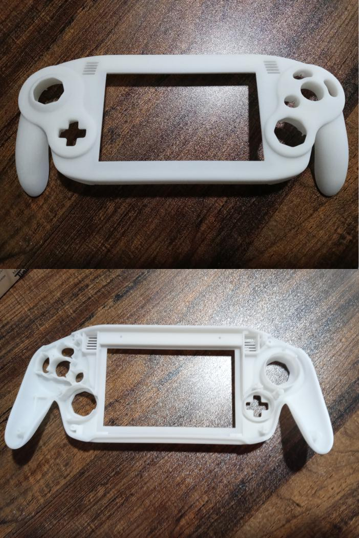
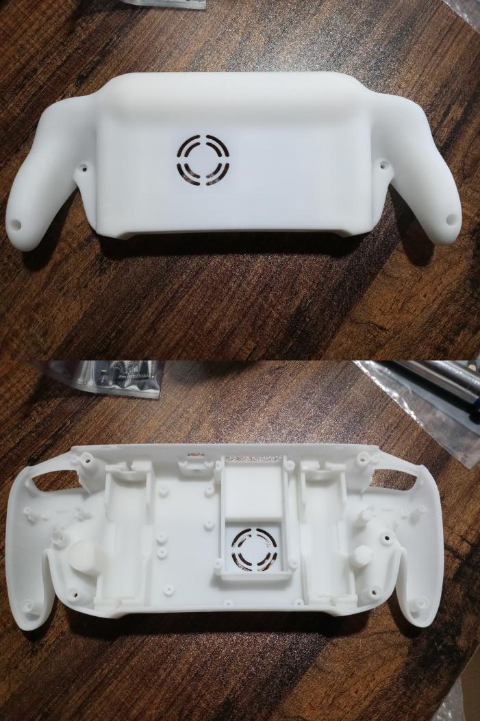
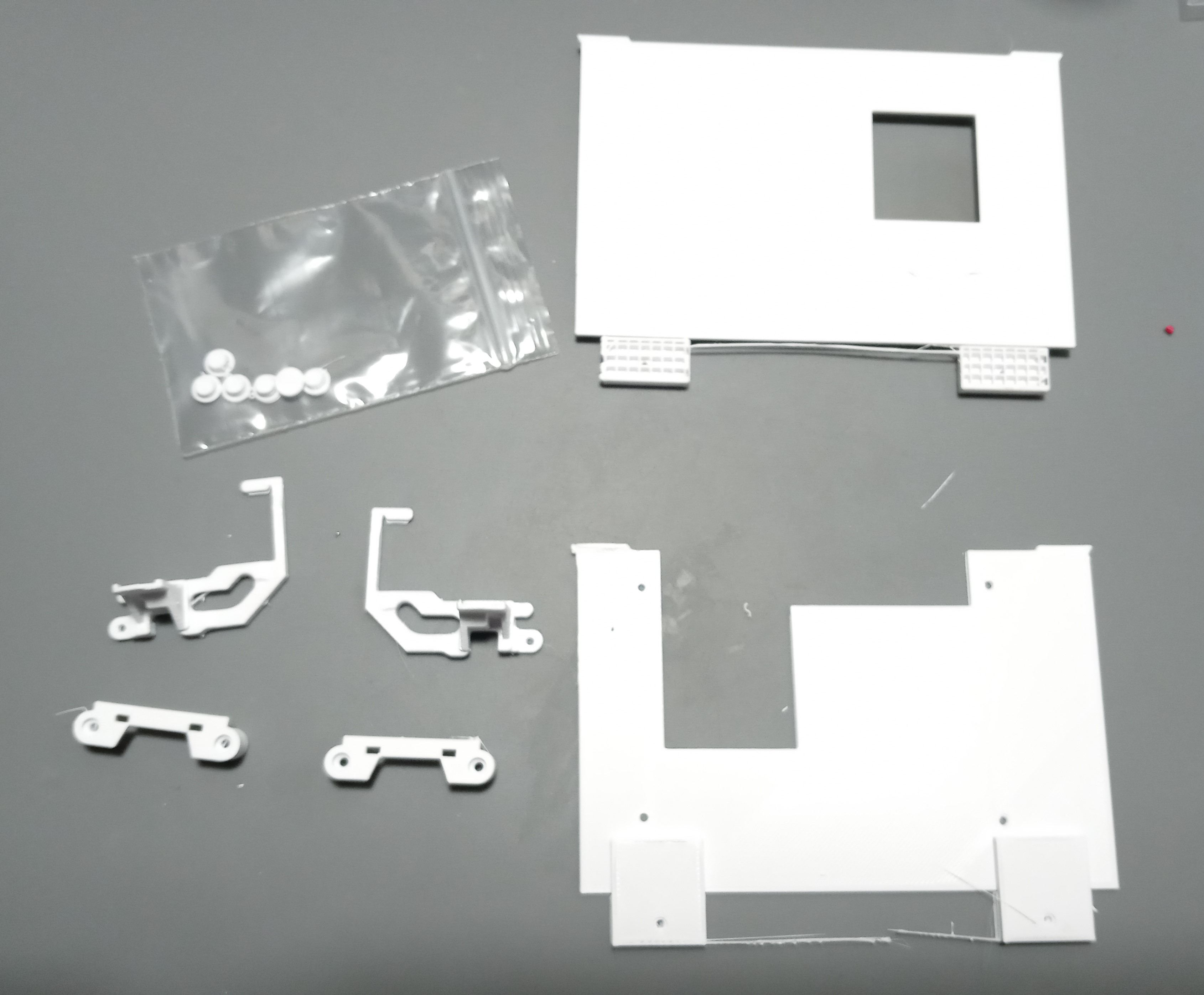
First off I got my shell. I got it from JLCPCB as an 8000 Resin print. Total cost for me with shipping was about $40 (was actually $50 but first time customers get a $10 coupon I guess.) They turned out really well! I got a simple white as I plan to theme my Ashida around the colors of a Wiimote. I wish it was a more vibrant white but I'm not willing to get it spray painted (it looks better on camera than irl)

Warping seems to be very minimal if at all, and a bit of wet sanding with some 800 - 1,500 grit sandpaper made this thing silky smooth (Pictures are pre-sanding). Still has a few visual imperfections, but they're somewhat hard to notice.
AshidaFrontPics.png

AshidaBackPics.png


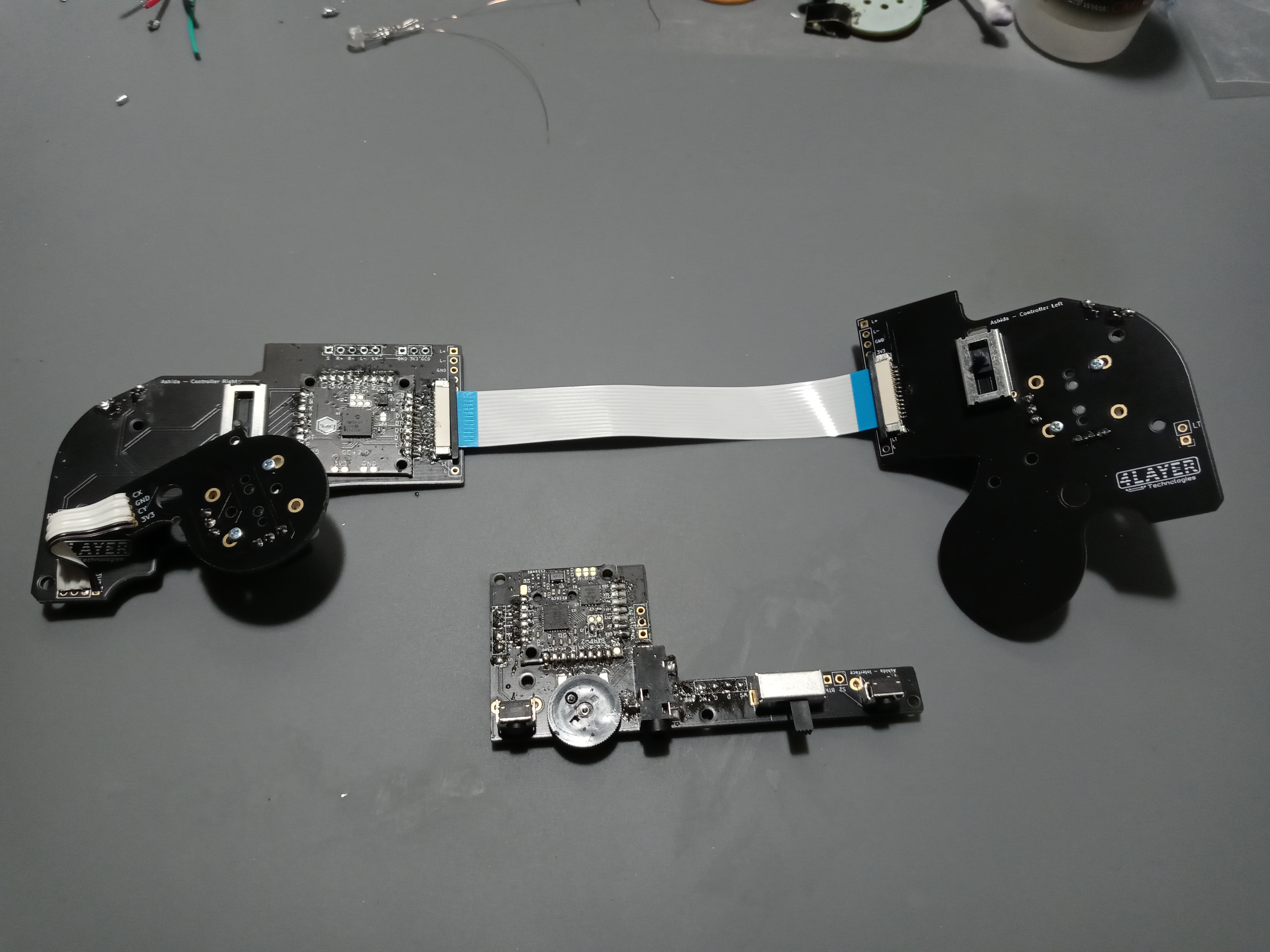
For the electronic side of this project, I started with the Ashida-specifc PCBs. I had wired them together and to the PMS but my wiring was iffy so I desoldered most of them and plan to redo them once I know the trim works. I got my stickboxes from a new Smash Ultimate Gamecube controller. For the Z buttons I got the OMRON 150gf switches according to the Fire's Tactile Z Mod Guide.

AshidaPCBs.jpg


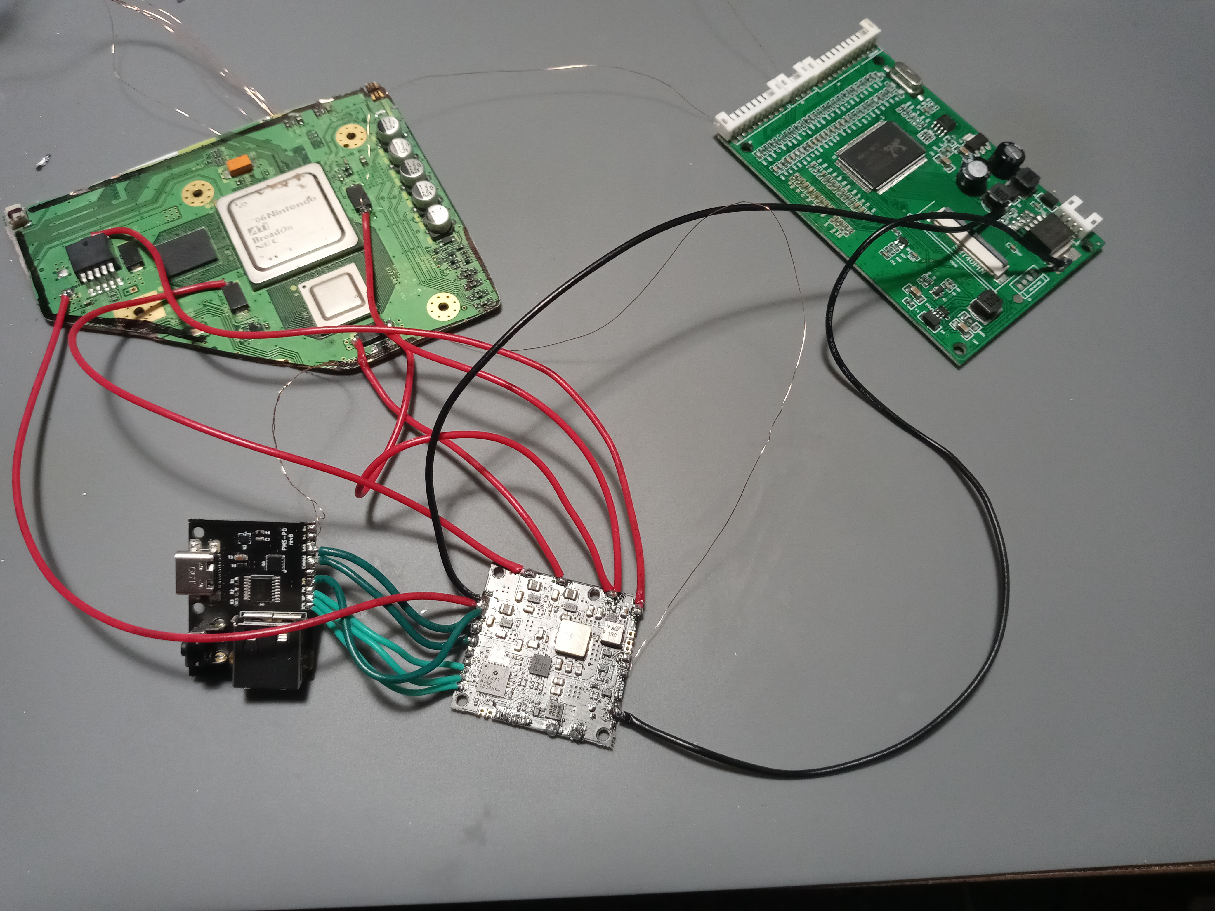
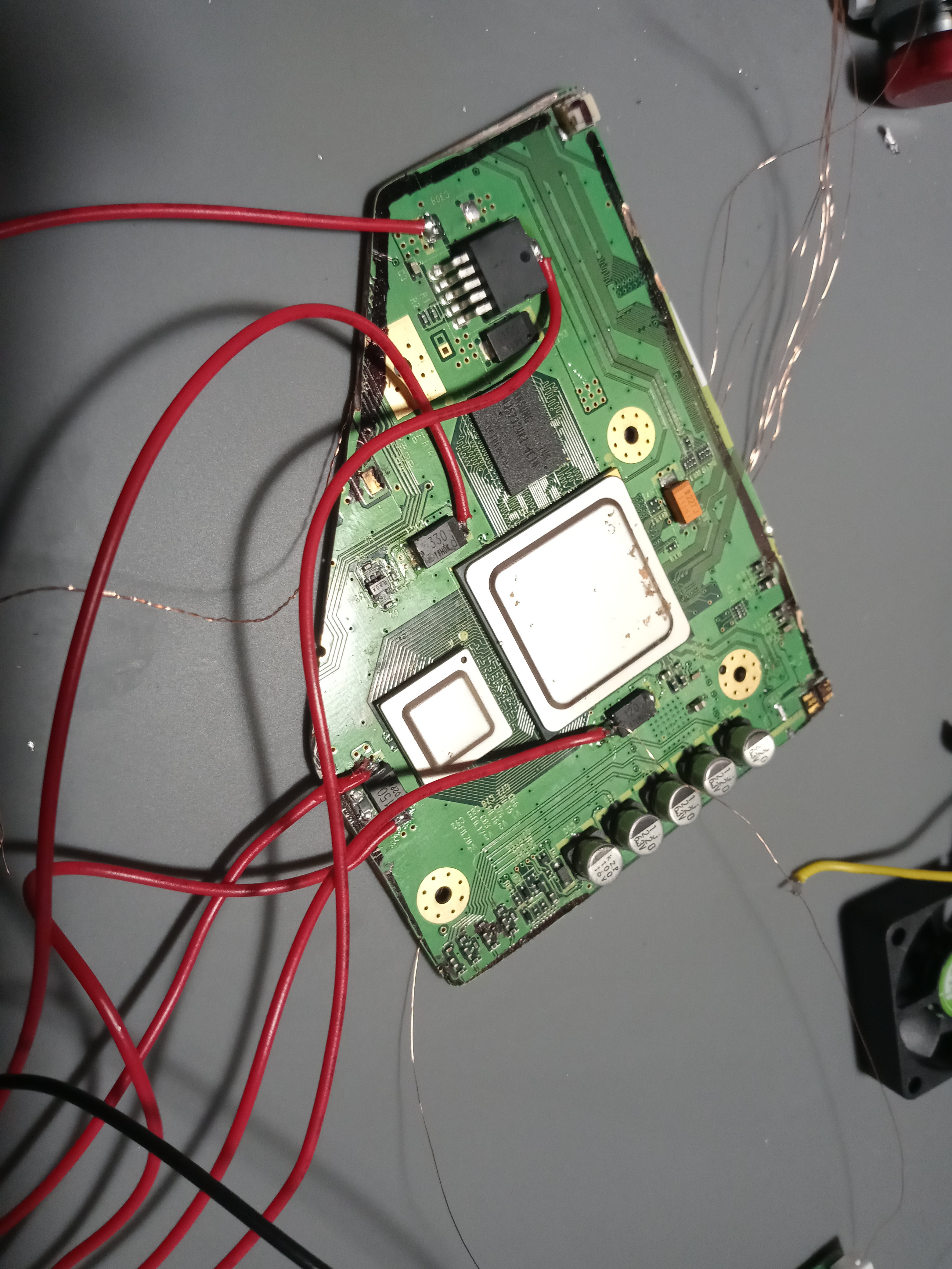
Next, I wired up everything I'm pretty sure I need to test the trim. I have a PMS-Lite so I kept the 1.8v regulator on the wii mobo. I got the PMS-PD 2 hooked up along with the D+ & D- for USB, and the PMS-Lite hooked up to the wii mobo, PMS-PD, and the driver board. I'm keeping the LCD wrapped up until I actually plug it in just in case (I'm a bit clumsy.) Haven't wired the batteries up yet since I'd like to get confirmation that I haven't done anything crazily wrong yet.

NOTE: I know the wires are a bit long, these are just temporary to test the trim itself. Once I know the trim works I'm gonna re-wire everything cleanly. The D- on the PMS-PD & GND from the driver board still need to be soldered in (didn't get enough enamel melted the first time for a good joint) but other than that all the wires should be good-to-go.
test1.jpg


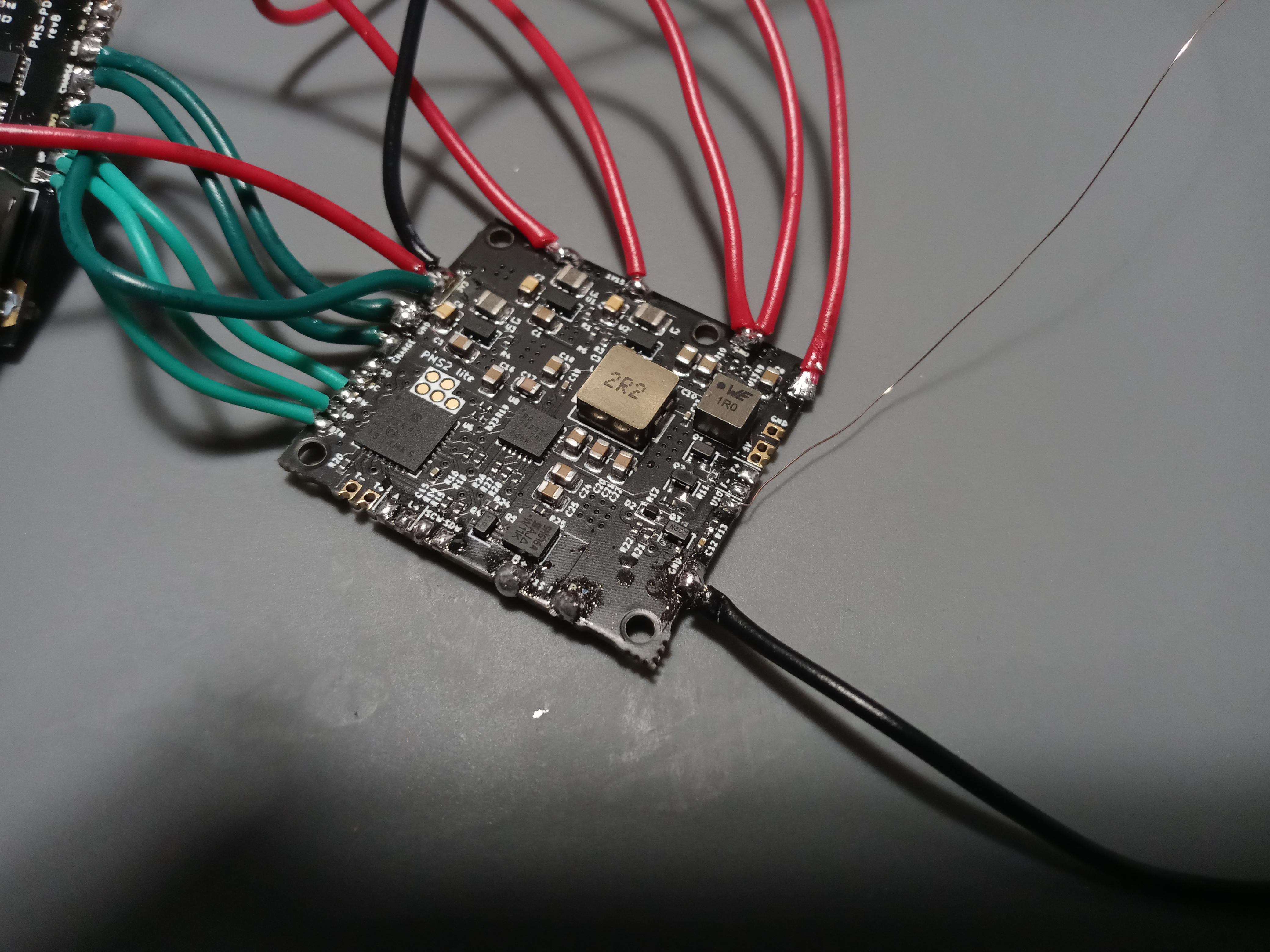
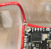
Here's my wiring for my PMS-Lite, The 1.8v wire definitely needs to have a better solder joint but other than that I think it should work.
test2.jpg

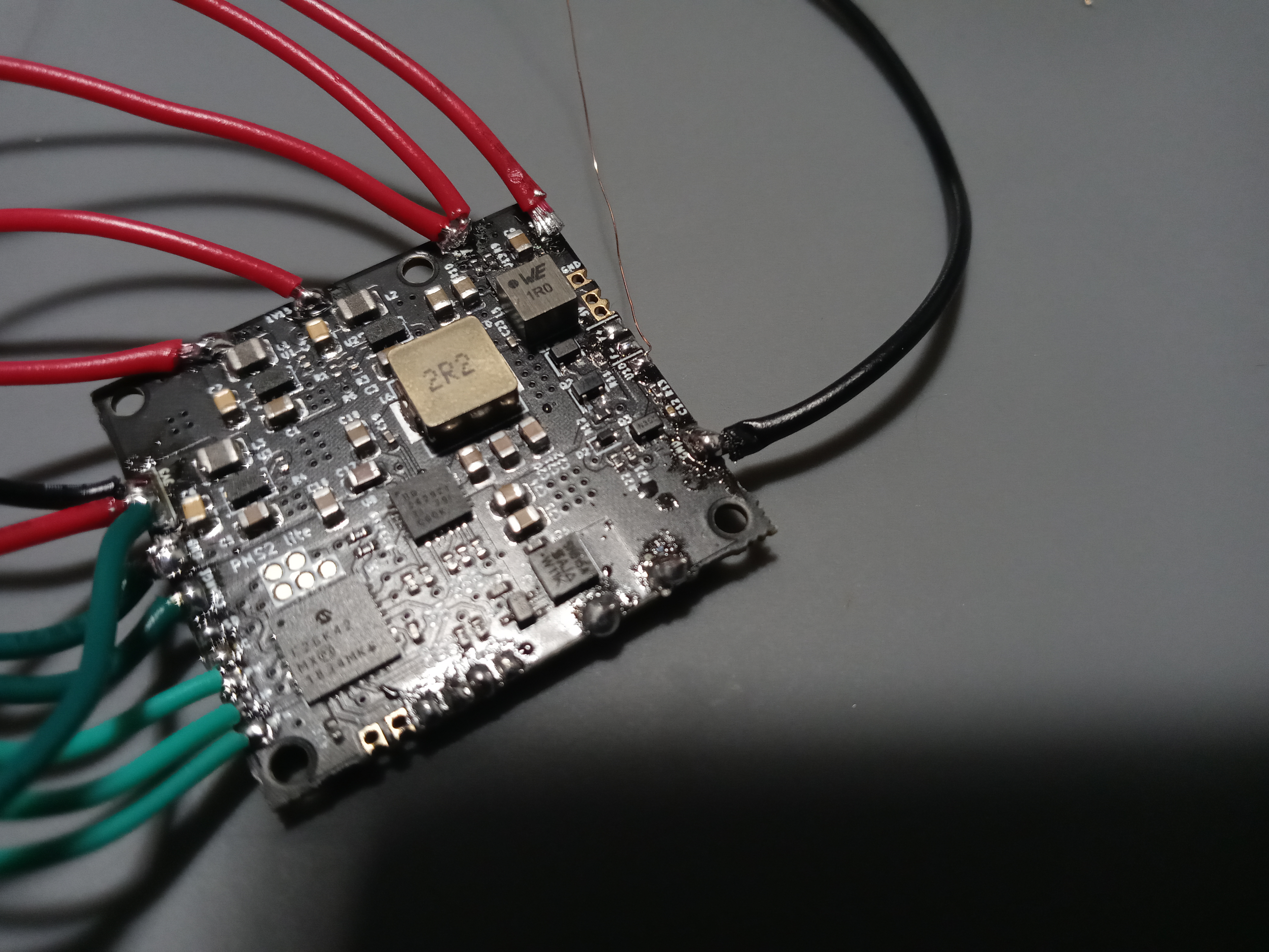
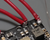
Different angle for the PMS-Lite.
test3.jpg


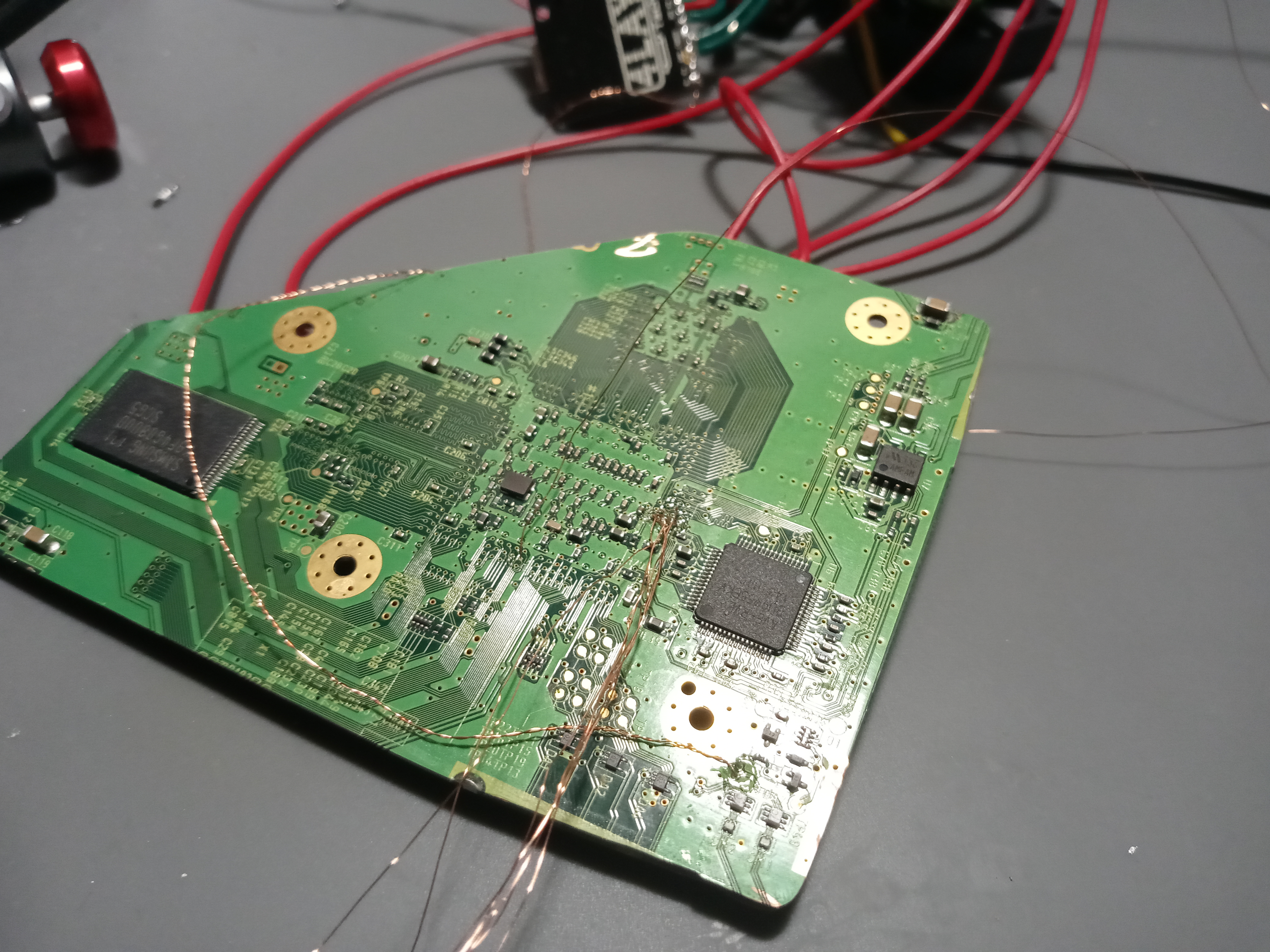
Note that I don't yet have the RVL-NTC soldered, I actually did at first. I tried to solder the T wire to it and the solder pad instantly fell off so I had to order a replacement.
test4.jpg


All of the extra magnet wire are for the many vias that need to be wired to. They're not currently connected to anything (except U10 & the USB wires) but I left them in since they're somewhat of a pain to solder to.
test5.jpg


I'm lucky enough to have a friend with a 3D printer that was willing to print everything for me. I still need to clean them up, but they turned out pretty good!
3Dprintmounts.jpg


This is where I'm at so far. If someone is able to confirm that I should be good to continue with testing my trim I'd appreciate it! I'm just anxious about accidentally frying my PMS-Lite lol. Also, I read from Gman in the 4Layer discord that the trim should be tested with fully charged batteries. Before turning the trim on should I just hook up the batteries and plug in a charger through the PMS-PD and will they charge that way? Just wondering about that, and if anyone can direct me to a battery mount I can buy to use for testing I'd appreciate it. Thanks for reading!
 

jefflongo

Broke BitBuilt
Staff member
.
.
Joined
Dec 15, 2016
Messages
1,017
Likes
1,361
Location
Santa Barbara, CA
Portables
3
The 1.8v wire definitely needs to have a better solder joint but other than that I think it should work.
Quick tip, since the PMS lite is not powering the 1.8V rail (and just needs the 1.8V as a reference), you can use a much thinner wire for it.

I'm just anxious about accidentally frying my PMS-Lite lol.
If you handle the batteries safely then there is little risk of frying things.
- Never solder to the PMS (or really anything, for that matter) when you have batteries in-circuit.
- Triple check that you connect your batteries in parallel and not in series
- Be extra cautious never to accidentally short the B+ and B- on the PMS
If you follow those 3 things you will not fry anything. It also helps to add an in-line power switch on the B+ rail so you can quickly disconnect the battery whenever needed.

Also, I read from Gman in the 4Layer discord that the trim should be tested with fully charged batteries. Before turning the trim on should I just hook up the batteries and plug in a charger through the PMS-PD and will they charge that way?
You can charge the batteries via the PMS/PD before powering up the Wii for the first time. Of course, check that nothing is shorted (i.e. voltage rails) with a multimeter before attempting to power up for the first time.
 
Joined
Jun 8, 2022
Messages
7
Likes
7
Location
Banana Hoard
Portables
Ashida (WIP)
Quick tip, since the PMS lite is not powering the 1.8V rail (and just needs the 1.8V as a reference), you can use a much thinner wire for it.
Ah, I knew it used it as a reference but didn't know I could use smaller wire. Does that mean magnet wire will suffice or just a slightly smaller wire? Either way, thanks!

- Be extra cautious never to accidentally short the B+ and B- on the PMS
Gotcha, and which would be a better way to wire the batteries up to the PMS? The picture on the left (wire splicing) or the picture on the right (both wires to the same solder pad)? (For both the B+ & B- pads)
solderjoint1.PNGsolderjoint2.PNG
If you follow those 3 things you will not fry anything. It also helps to add an in-line power switch on the B+ rail so you can quickly disconnect the battery whenever needed.
I think I understand what you mean here but just to make sure: do you mean to solder an extra power switch between wires coming from the batteries and the B+ pad on the PMS? I bought an extra switch (same one used on the interface of the Ashida PCB), should I just wire to these pins?
switchquestion.PNG


You can charge the batteries via the PMS/PD before powering up the Wii for the first time. Of course, check that nothing is shorted (i.e. voltage rails) with a multimeter before attempting to power up for the first time.
I figured that's how it was intended but just wanted to make sure. Thanks for your help, really helped to clear some of the anxiety I have about the PMS already lol. Thanks again!
 

jefflongo

Broke BitBuilt
Staff member
.
.
Joined
Dec 15, 2016
Messages
1,017
Likes
1,361
Location
Santa Barbara, CA
Portables
3
Ah, I knew it used it as a reference but didn't know I could use smaller wire. Does that mean magnet wire will suffice or just a slightly smaller wire? Either way, thanks!


Gotcha, and which would be a better way to wire the batteries up to the PMS? The picture on the left (wire splicing) or the picture on the right (both wires to the same solder pad)? (For both the B+ & B- pads)
View attachment 23117View attachment 23118

I think I understand what you mean here but just to make sure: do you mean to solder an extra power switch between wires coming from the batteries and the B+ pad on the PMS? I bought an extra switch (same one used on the interface of the Ashida PCB), should I just wire to these pins?
View attachment 23116


I figured that's how it was intended but just wanted to make sure. Thanks for your help, really helped to clear some of the anxiety I have about the PMS already lol. Thanks again!
1. I don't quite remember what 1.8v is used for on the PMS besides pulling up the Wii i2c rails, it's possible that that's all it's for. Maybe just use like a 26 awg wire just in case.

2. Neither, really. What I did in my ashida is connected the battery clips in parallel and then had a single power and ground wire go to the PMS. Then put the batteries in after the soldering was done.

3. You'd have to check the specs for that switch but I doubt that switch will be able to handle ~3A of current (it just toggles a microcontroller pin for the PMS). If you want to have an in-line switch for the battery you'll probably want one of those flip switches.
 
Joined
Jun 8, 2022
Messages
7
Likes
7
Location
Banana Hoard
Portables
Ashida (WIP)
1. I don't quite remember what 1.8v is used for on the PMS besides pulling up the Wii i2c rails, it's possible that that's all it's for. Maybe just use like a 26 awg wire just in case.

2. Neither, really. What I did in my ashida is connected the battery clips in parallel and then had a single power and ground wire go to the PMS. Then put the batteries in after the soldering was done.

3. You'd have to check the specs for that switch but I doubt that switch will be able to handle ~3A of current (it just toggles a microcontroller pin for the PMS). If you want to have an in-line switch for the battery you'll probably want one of those flip switches.
1. Gotcha, I think I have some 28 awg wire that should work perfectly for it.

2. Can't believe the thought to wire them like that didn't seem more obvious to me, I'll definitely just wire em like that.

3. Yeah that's not super surprising, just figured I'd check if somehow it could work. I'm on somewhat of a time crunch so I might go without the switch for testing

Thanks again for your help! I feel way more confident about this now, I'll make sure to update this thread with my results soon!
 

Carbon

.
Joined
Jun 10, 2022
Messages
2
Likes
0
Where did you get the files for the case from? IDK where to look :/. Other than that the build looks nice!
 
Joined
Jun 8, 2022
Messages
7
Likes
7
Location
Banana Hoard
Portables
Ashida (WIP)
UPDATE: I tested my trim and it worked! Not the best setup for testing but it was temporary and did the job.
testedbuild.jpg


After testing, I started to wire up some of the other things more cleanly. I also started to wire VGA & audio and have come across a problem....
whoops.jpg


As you can see, the pins on the right are very messed up. I was trying to wire up audio when I noticed I had bridged two pins on accident, and only made it worse trying to remove the solder with some wick. I don't think they'll still work, but if anyone knows for sure please let me know. The audio pin should be fine but I think a 3.3v pin is bridged to GND now and I've been unable to remove the solder since my iron isn't small enough.

If it is toast (as I expect), I still have a back-up 4Layer wii that I can use.
 

Wesk

Undervolting....
Staff member
.
.
Joined
Jul 12, 2017
Messages
868
Likes
2,167
Location
Queensland, Australia
Why are you wiring directly to the AVE when you can wire to the vias next to it?, the only wires that need to be wired directly on the AVE legs are H and V sync.
 
Joined
Jun 8, 2022
Messages
7
Likes
7
Location
Banana Hoard
Portables
Ashida (WIP)
Somehow it never occurred to me while looking at the video relocation diagram that I should just wire to the vias. Now that I'm looking at it again it seems pretty obvious, would've saved me quite a headache lol. I have the H & V wired up but I'll relocate the other wires to the proper vias if you think trying to salvage my solder job on this chip is worth it. Either way, thanks!
 

jefflongo

Broke BitBuilt
Staff member
.
.
Joined
Dec 15, 2016
Messages
1,017
Likes
1,361
Location
Santa Barbara, CA
Portables
3
Rule of thumb, don't use solder wick on SMD components with the intent to remove all of the solder. It won't happen. It's fixable but it depends on your skill level and patience. What you will have to do is heat the bent pins, and push them back into place with tweezers while the solder is molten. Then to fix the bridging you want to add a generous amount of flux and drag your iron across the pins (Google drag soldering).
 
Joined
Jun 17, 2022
Messages
36
Likes
24
Drag soldering isn't necissarily the best way to deal with bridging on this type of chip. It is very useful the bridging isn't too bad, but it is mostly just spreading around the solder that is on the pins, if you have too much solder you are just going to move the bridge or make more. Another approach that will helpis to very thoroughly clean your tip, then place your iron perpendicular to the pins adjacent to the bridge and gently touch it to the bridge, then slowly pull the iron away from the pins. Some of the solder from the bridge should be pulled onto your iron and off of the chip, it might not remove enough solder all at once, but if there is still too much solder you can just clean the tip again and repeat. Using that in combination with drag soldering can pretty much always fix bridging on these types of chips, but I would never put wick anywhere close to those small pins, it is way too easy to bent pins or rip pads when stuff is that small and close together
 
Joined
Jun 8, 2022
Messages
7
Likes
7
Location
Banana Hoard
Portables
Ashida (WIP)
UPDATE:

Thanks for the advice about the chip! I went on vacation after the last update and then got sick right after so I haven't had a chance to work on this until today. I tried what you guys said and it actually seemed to be working until I put too much pressure on one of the pins and snapped it off :/

While preparing to start working on an Ashida a few months ago I had the good idea of buying 2 4Layer Wiis in case I messed something up. So luckily I had a better condition backup to use instead of the trim I've messed up. After trimming it and wiring it up, it works just fine!
trim2test.jpg

(Ignore the mess lol)

The D+ and D- wires are backwards so that's why the USB wasn't detected, just gotta swap those around. Next I'll wire up VGA without messing it up (hopefully lol). One last thing I'm wondering about: are my wires from the PMSLite to Wii mobo too long? They were just for testing but I'm wondering how much shorter I should make them, like 1/2? 1/3? Thanks!
 

CrazyGadget

Crazy Helpful, CrazyGadget
.
Joined
Jun 6, 2020
Messages
607
Likes
871
Location
Downing's Closet
Portables
???
Looking good! Those wires from the PMS to the Wii don't look too long to me at all, although the 3v3 line could probably come down a bit. The goal is to have it as short as possible, so just long enough for the mobo to fit in its spot in the case.
 
Top