Black Screen When Testing Wii Trim

Joined
Apr 22, 2023
Messages
33
Likes
11
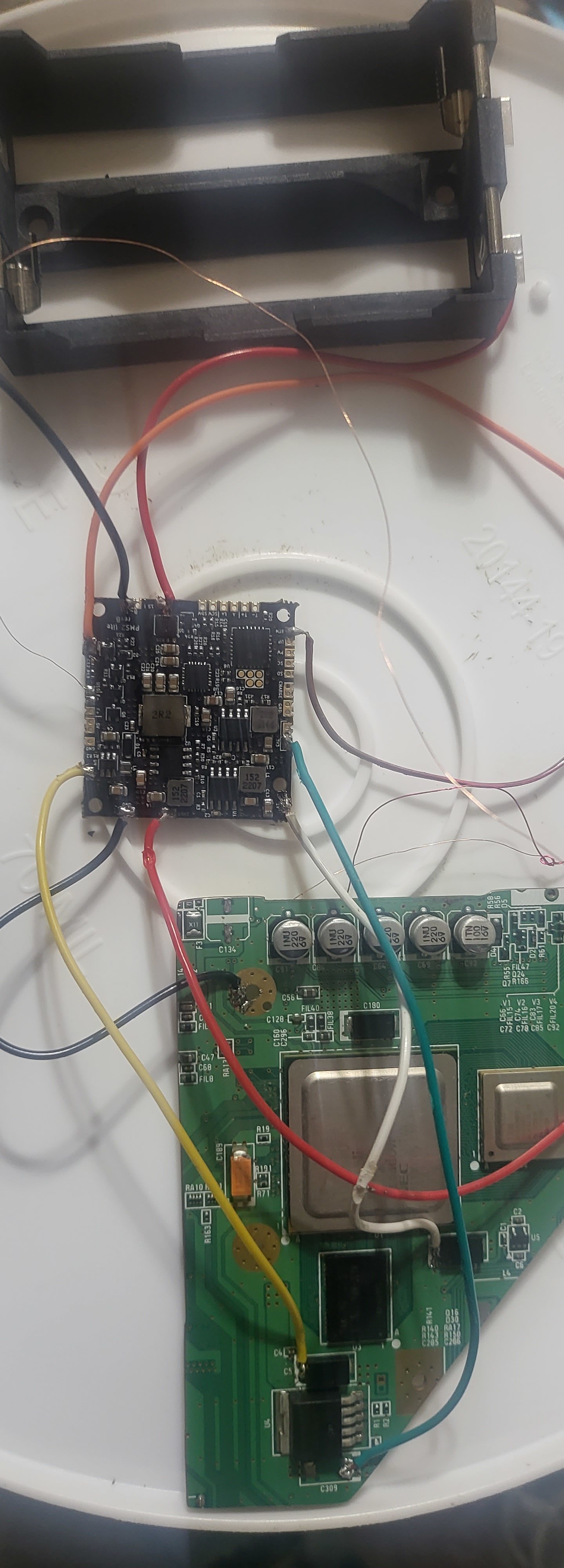
I trimmed a couple of 4 Layered Wiis. I've been testing them out for the last couple of days but no success.
They worked fine prior to the trim as I did all the prerequisites(building a Ashida).
I don't recall all the ohm values off hand and they seemed comaparabel to the chart from here. I can disconnect
the lines from the wii trim and grab them.

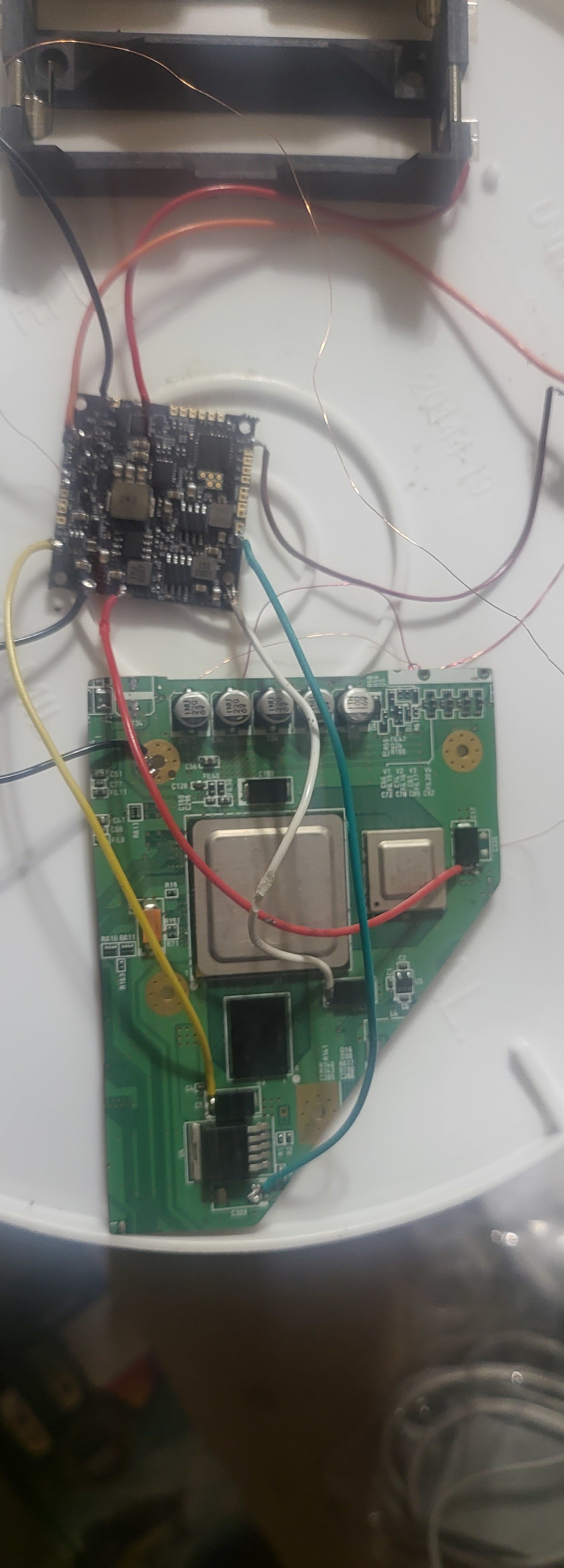
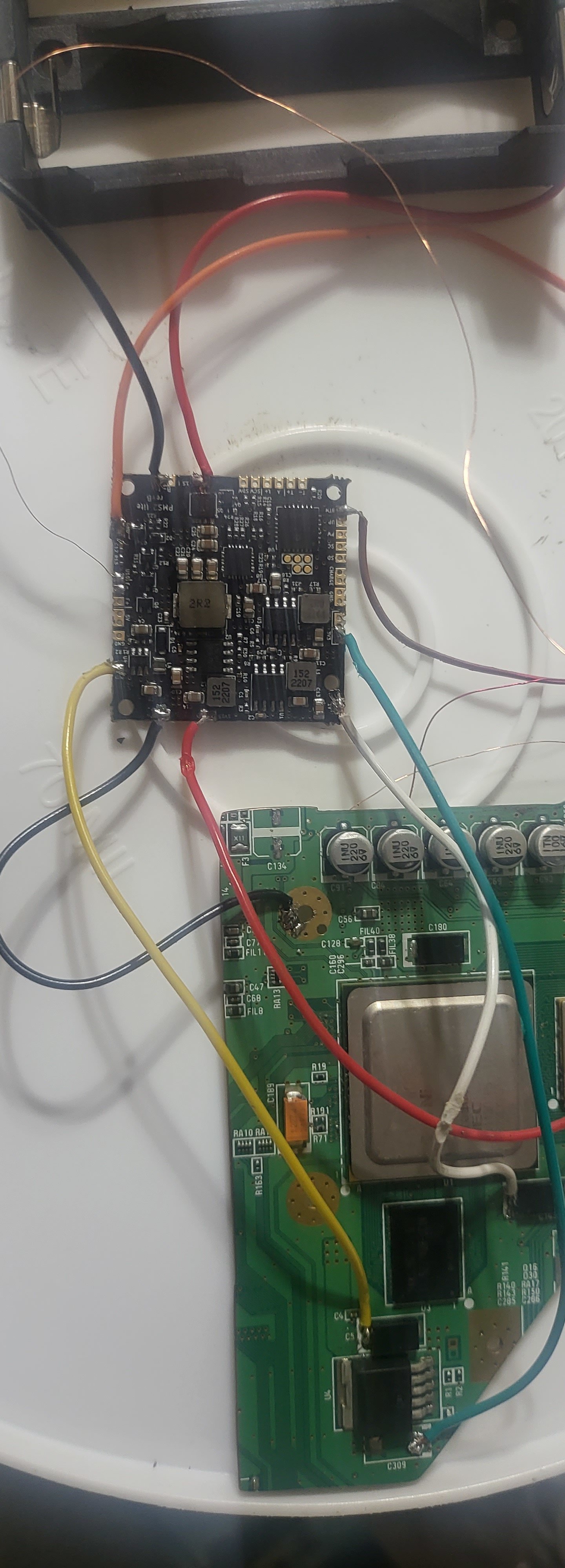
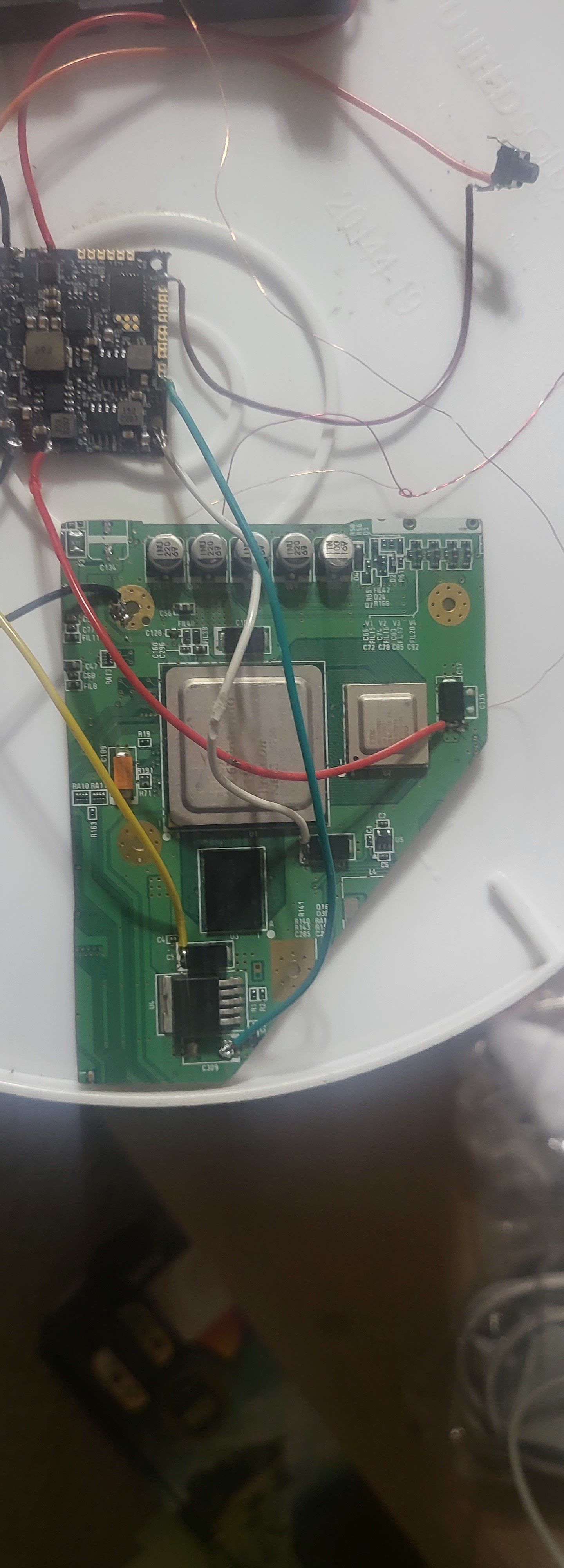
Voltages checked from pms : 3.17, 1.77, 1.03, and 0.82 respectively from the 3.3, 1.8, 1.15, and 1 volt lines on the wii.

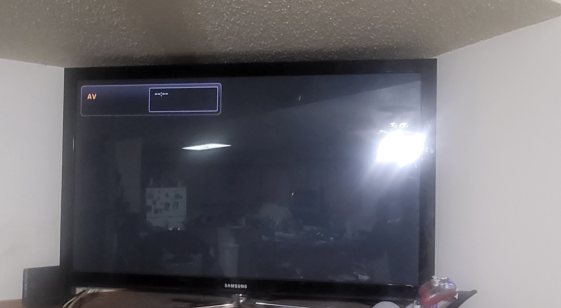
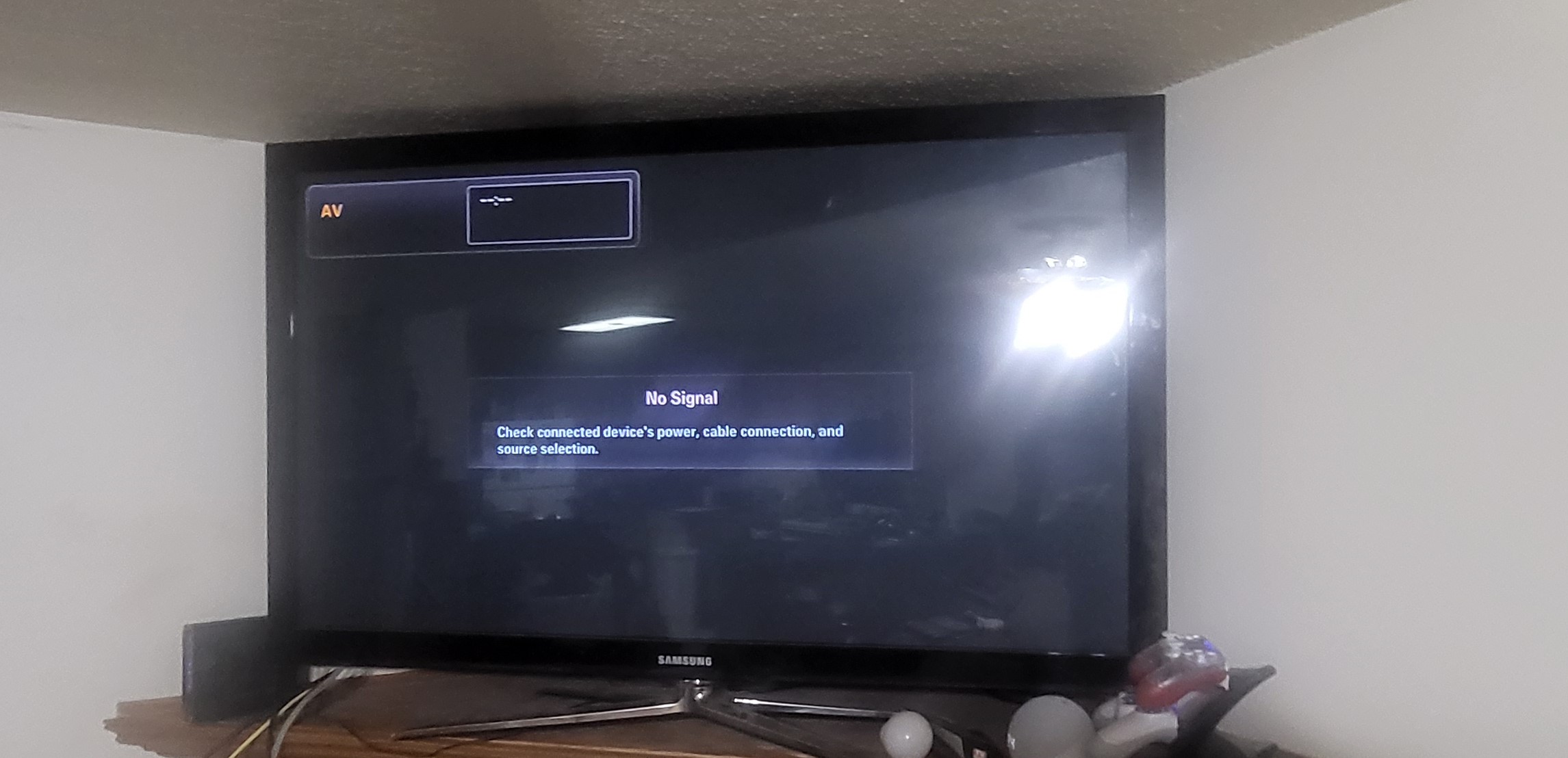
I get a black screen when I power the pms from a no signal. I was expecting a error message I asssumed but it stayed black.
The board did get warm. I rechecked connection and charged battery, think it as pretty low on initial testing.

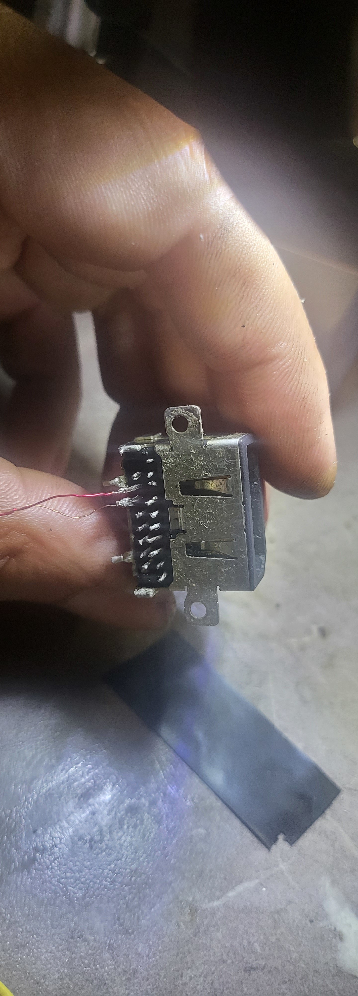
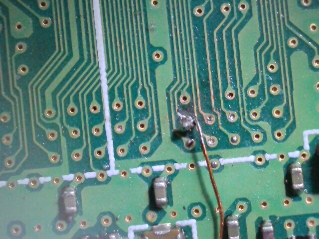
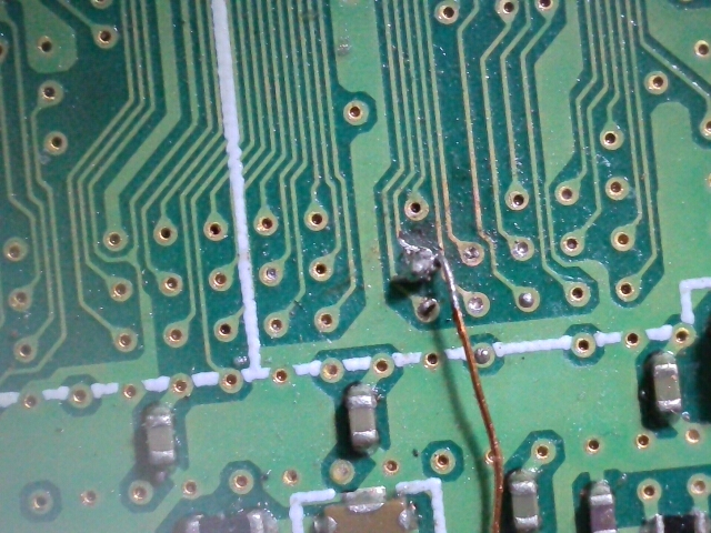
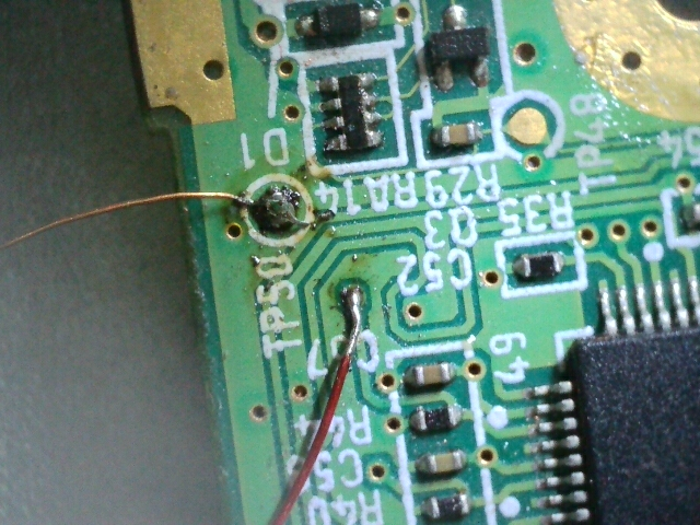
I used 34 awg magent wire for the u10 via.

Should I get a black screen with a error message that should appear briefly after applying power to wii trim?
I didnt want to continue untill I have working wii trim.

This my 1st portable attempt by the way.

Thanks for any replies.


20230616_210124.jpg
20230616_212255.jpg
20230616_212309.jpg
20230616_212316.jpg
20230616_212319.jpg
20230616_212436.jpg
20230616_212452.jpg
Image_2023-06-16 21_11_40_520.png
Image_2023-06-16 21_11_42_282.png
Image_2023-06-16 21_12_27_516.png
 

Retro95

.
2023 3rd Place
Joined
Mar 29, 2023
Messages
180
Likes
235
Location
Oregon
Portables
2
You should indeed get a failure screen stating that RVLoader could not initialize the FAT32 device.

As for your voltage ratings. Those ratings are far too low to properly boot the Wii. You want to see a 5 percent drop max.

The voltage drop is likely an issue of cold solder joints. Some of those power rails don't have adequately tinned wire conductors and have cold joints. What's your soldering iron set to?

This could also be from low input power. What's your battery voltage at? Optimal voltage should be around 3.6-3.7 volts.

Also I'm not sure if that U10 solder is gonna cut it.. it looks pretty obliterated.

EDIT: I see you only have 1 GND connection to the Wii. You'll want a minimum of 2 GND wires from PMS to Wii.
 
Last edited:
Joined
Apr 22, 2023
Messages
33
Likes
11
Temperature is set to 385 (I realized that's too high, I had it lower).

Battery was 3.61. It is fully charged now at 4.12

What would you suggest about u10? I tried a 30 awg magent wire unsuccesfully. Then tried a 34 awg but had difficulty to get it insde via then solder.

Admittedly fatigue had been setting in.
 

Retro95

.
2023 3rd Place
Joined
Mar 29, 2023
Messages
180
Likes
235
Location
Oregon
Portables
2
Before attempting to resolder the very delicate vias. I would highly recommend getting some high quality flux.

Anything by Kester is amazing. It's on Amazon. Apply lots of flux to the U10 joint, and try reflowing it briefly. You'll notice the flux makes the joint nice and uniform and shiny.

Use the flux to redo all your PMS and Wii power connections as well. Adding an additional ground.

Then make sure all your power rails are within 5 percent tolerance at the Wii itself.

If it doesn't boot after that it's possible that the U10 via is not recoverable.


I too destroyed my first two Wii trims in a similar fashion.

If you want to build up your soldering skills there is a plethora of "Soldering practice projects" on Amazon for 15-20$ that come with PCBs, a bunch of different types of SMD components like LEDs, voltage regulators, resistors, etc.

They have fantastic documentation and it will allow you to develop your skills on soldering extremely tiny components so your next Wii trim will be a piece of cake!
 
Joined
Apr 22, 2023
Messages
33
Likes
11
Ok fixed the cold joints. Added 2nd ground(does it matter where on the trim ?).

3.28, 1.77, 1.13, and 0.97 respectively for the 3.3, 1.8, 1.15, and 1 volts lines.

I revisited the u10 via.

So far still just black screen with no error message.

Image_2023-06-17 13_30_22_174.png
 
Joined
Apr 22, 2023
Messages
33
Likes
11
Before attempting to resolder the very delicate vias. I would highly recommend getting some high quality flux.

Anything by Kester is amazing. It's on Amazon. Apply lots of flux to the U10 joint, and try reflowing it briefly. You'll notice the flux makes the joint nice and uniform and shiny.

Use the flux to redo all your PMS and Wii power connections as well. Adding an additional ground.

Then make sure all your power rails are within 5 percent tolerance at the Wii itself.

If it doesn't boot after that it's possible that the U10 via is not recoverable.


I too destroyed my first two Wii trims in a similar fashion.

If you want to build up your soldering skills there is a plethora of "Soldering practice projects" on Amazon for 15-20$ that come with PCBs, a bunch of different types of SMD components like LEDs, voltage regulators, resistors, etc.

They have fantastic documentation and it will allow you to develop your skills on soldering extremely tiny components so your next Wii trim will be a piece of cake!


Thanks for the input and help. Think I killed the u10 unfortunately. I had went back and redid what yo suggested prior to seeing this post.

Well I'll track down a couple more wiis and start again. I think the flux I have is ok (paste and liquid), but will look into gettind some kester.

I got careless and rushed the testing. Some valuable lessons learned and I will continue to keep learning.

Thanks again for taking the time to respond.


What I had on hand flux-wise.

Screenshot_20230617_180743_Amazon Shopping.jpg
Screenshot_20230617_180650_Amazon Shopping.jpg
 

Stitches

2 and a Half Dollarydoos
Staff member
.
.
Joined
Feb 5, 2017
Messages
3,853
Likes
3,026
Location
Banana Bender Land, Australia
Portables
6
Ok fixed the cold joints. Added 2nd ground(does it matter where on the trim ?).

3.28, 1.77, 1.13, and 0.97 respectively for the 3.3, 1.8, 1.15, and 1 volts lines.

I revisited the u10 via.

So far still just black screen with no error message.

View attachment 28196
Those voltages are much better and should allow a successful boot. How long is your composite wire?

Also the MG Chemicals flux you have is fine, you may just have not been using enough. The rosin stuff however is garbage, I'd bin it.
 
Joined
Apr 22, 2023
Messages
33
Likes
11
Those voltages are much better and should allow a successful boot. How long is your composite wire?

Also the MG Chemicals flux you have is fine, you may just have not been using enough. The rosin stuff however is garbage, I'd bin it.

I hosed the u10 via unfortunately.
I read through a lot of material on here and watched a couple of ginger of oz videos.

I didn't think of the length of the composite line. It was just over two feet in length. I used 2 lines of 30 awg magnet wire (twisted). I didn't recall seeing any specific details aside from using the correct pins from the bitbuilt diagram for the audio/video.
Should those be shortened and used with a bigger gauge?
 

Stitches

2 and a Half Dollarydoos
Staff member
.
.
Joined
Feb 5, 2017
Messages
3,853
Likes
3,026
Location
Banana Bender Land, Australia
Portables
6
The wire should definitely be shortened to be less than a foot, but I don't think the gauge matters terribly. It's only a signal line, so 30AWG magnet wire should be plenty sufficient
 
Top