
- Joined
- Jun 28, 2016
- Messages
- 8
- Likes
- 2
Will lipo batteries work with the 2s cmb?
They'll work, yes. They're just not recommended for first time builds due to safety concerns.Will lipo batteries work with the 2s cmb?
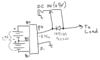
This is not enough. Lithium batteries can’t be charged with a constant voltage supplyCan't you do the same thing with a circuit like this? Just a switching DC Jack and a Diode. The forward voltage of the diode must be taken into account, but should be a simple solution. Apologies for the badly drawn schematic.
What Aurelio said and also a mechanical switch is far too slow even for a CPU switching at 93.75mhz (93,750,000 times a second); otherwise a relay would be a viable solution as well. Think of a transistor like a variable resistor, like a potentiometer that switches extremely quickly. However it never truly completely disconnects the battery, it just puts a massive amount of resistance between it and the load, like a volume pot. The voltage from the battery drops out as the input voltage from the external power switches the diode back around and the capacitor keeps the voltage from dropping. This switching is more analog with the parts working in beautiful harmony to maintain voltage.Can't you do the same thing with a circuit like this? Just a switching DC Jack and a Diode. The forward voltage of the diode must be taken into account, but should be a simple solution. Apologies for the badly drawn schematic.
Not really. Lithium batteries need first a constant current charging, followed by a constant voltage one. This is done because the internal resistance of lithium cells is very low, therefore applying a 4.2V/cell would push too much current in the batteries, destroying them and causing fire hazardYes you are right. The diagram I drew assumes the protection module has a circuit which stops charging the batteries once they reach 4.2V. I assume this is what you are talking about.
What Aurelio said and by abusing the over voltage protection of a battery protection board you can't get a full charge anyway. A smart charger switches from CC to CV while tapering the current down when it reaches 4.1-4.2 volts (see the graph in the original post). Without this switch the protection board will disconnect the battery at 70% charge.Yes you are right. The diagram I drew assumes the protection module has a circuit which stops charging the batteries once they reach 4.2V. I assume this is what you are talking about.
That board doesn't provide smart charging. The dead give way is generally a smart charger has a coil on board. If you are planning on a 2s battery just use the Red Board described above.I believe I understand now, thank you for clarifying. I was under the impression that the circuitry inside the protection module will provide the CC and switch to the CV at the correct time. I would think this depends on the protection module? For example does this protection module work the way you two describe, or will it do what a smart charger does? I would think it would still need a smart charger from what you are both saying. https://www.amazon.com/gp/product/B00N48RCS8/ref=oh_aui_detailpage_o01_s00?ie=UTF8&psc=1
Additionally, Miceeno are you talking about issues with switching speeds in the device being powered? Such as a CPU on an N64 freezing because of an insufficient switching time for when the battery power and the wall power switch?
I design guitar pedals for a living so I am familiar with the negative tip configuration, this is why I was hoping to use it.
Yeah sounds about right. Let us all know how it turns out. In my original post I ordered a handful of parts so I could build a demo circuit as fast as possible with the intention of fine tuning it later but I got busy with another project. It turns out my "let's hurry and body work and paint a truck before it gets too cold" project turned into a two vehicle, two month ordeal because of rust repair and weather.This is a PFET used for power switching in portable applications.
https://www.mouser.com/ProductDetail/Micro-Commercial-Components-MCC/SI2305-TP/?qs=sGAEpiMZZMshyDBzk1/Wi90KS4xNEreAqpw%2bazpwlG3n20a/hTm1HA==
I would imagine the schottky diode just needs a low forward voltage, I would imagine the 1N5819 would work for the circuit.
The pull down resistance is likely 100k or 1Meg. The cap value just needs to be big enough to hold a charge when the FET turns on or off.
") . However, I would like a long battery life and a small footprint for my battery. Using four 18650 3.7 3600mAh cells in a 2s2p configuration should give me about 4-5 hours of play time on a N64 portable and a small enough footprint.
. However, I would like a long battery life and a small footprint for my battery. Using four 18650 3.7 3600mAh cells in a 2s2p configuration should give me about 4-5 hours of play time on a N64 portable and a small enough footprint.You have to be careful with charging lithium ion cells. The faster you charge them, the more likely something bad could happen. Also, charging lithium ion cells fast can shorten the life of the battery.I would use the Red Board, but the charging current of 1A is annoying if my batteries are 6.8A. Its going to take a long time to charge. The TP5100 is a better option if I want to use a 2s2p configuration with my cells.