Worklog First portable and first Ashida build

Joined
Jul 20, 2023
Messages
17
Likes
5
Hey everyone, I am building my first Ashida. Wanted to make a worklog to track my progress as well as ask a bunch of questions because I am very new to this. I have read a couple other Ashida worklog threads, watched Ginger's Ashida build VOD four times now, gone through the Ashida BOM, G-boy guide and the 4layer schematics. (however I have never used KiCAD before and am having a tough time opening the .mod files)

This is also my first time on a forum and I will do my best to follow the bitbuilt rules and forum etiquette and will work to correct any mistakes I make in that regard.

THE PARTS:
  1. I am using an RVL-PMS-2, RVL-AMP, the Ashida PCB controller set with GC+ 2, and PMS-PD 2 along with the IPS screen and blue driver board that I modified.
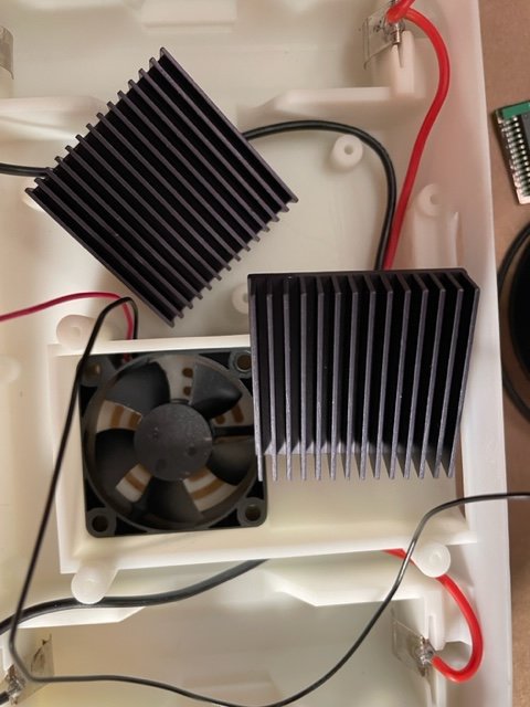
  2. the headphone jack, tact buttons, volume potentiometer, battery clips, ribbon cable, ribbon cable connectors, speakers, batteries and power switch are all the ones on the BOM. The fan I got is an Orion fan like on the bom but was missing a lot of the cooling information and the one on the BOM is backordered for a while. The heat sinks I also had to swap out because of backordering and believe I got suitable replacements. The screws I am harvesting from the wii.
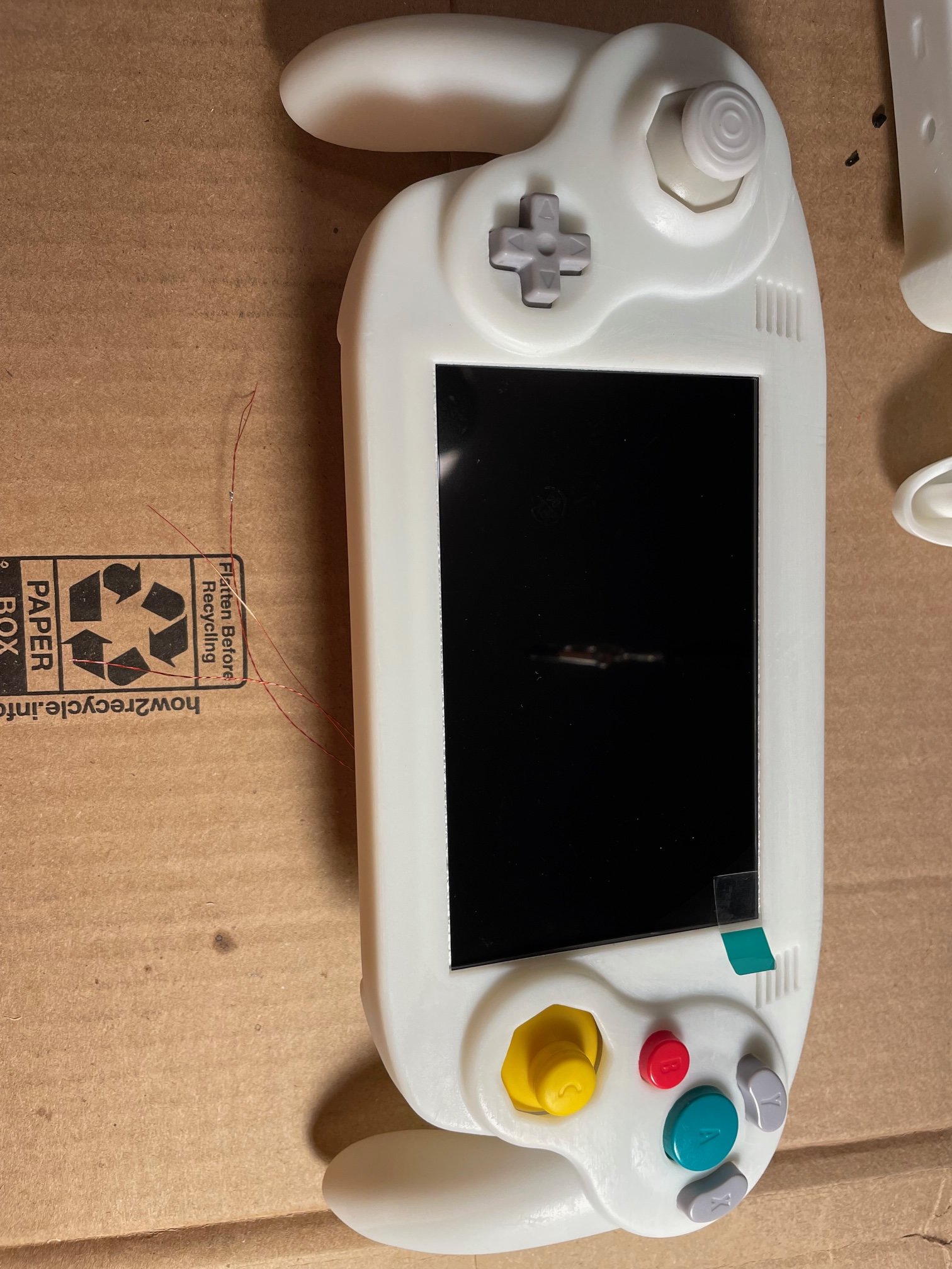
  3. The 3D prints I used PCBway, I did resin for the shell and tact buttons and ABS for the brackets and mounting parts.
  4. Populating the Ashida PCB controller set are OEM gamecube controller stickboxes, triggers, buttons, membranes, analog trigger potentiometers that I salvaged from two gamecube controllers I accidentally murdered a year ago when I was first learning to solder.
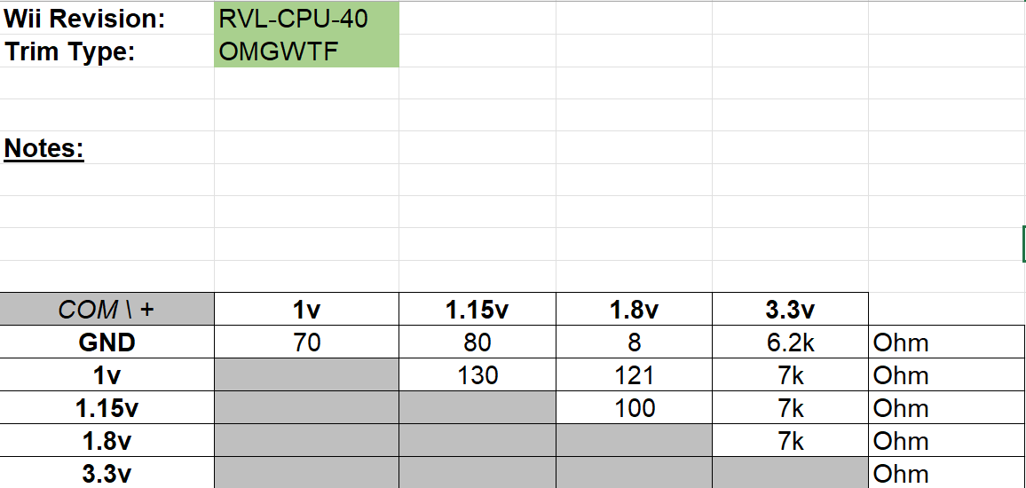
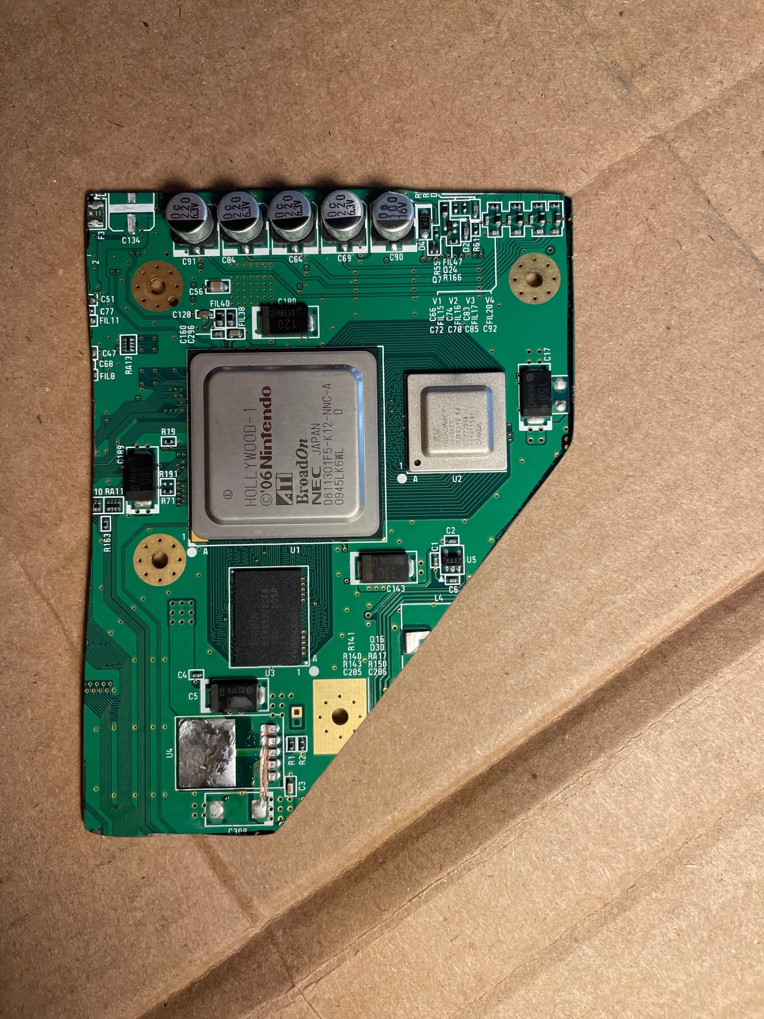
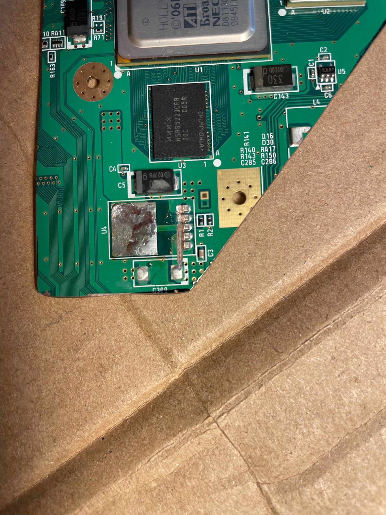
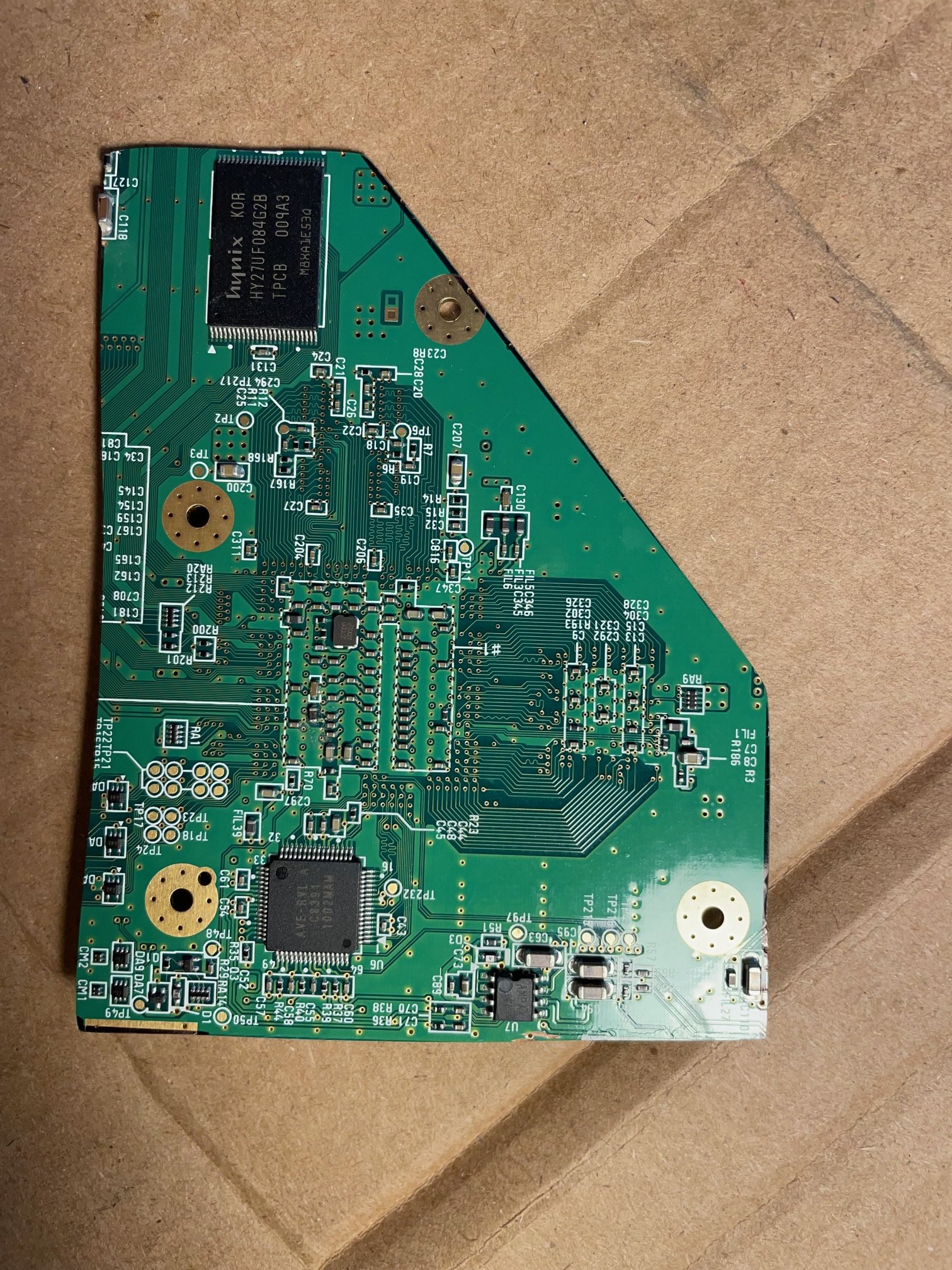
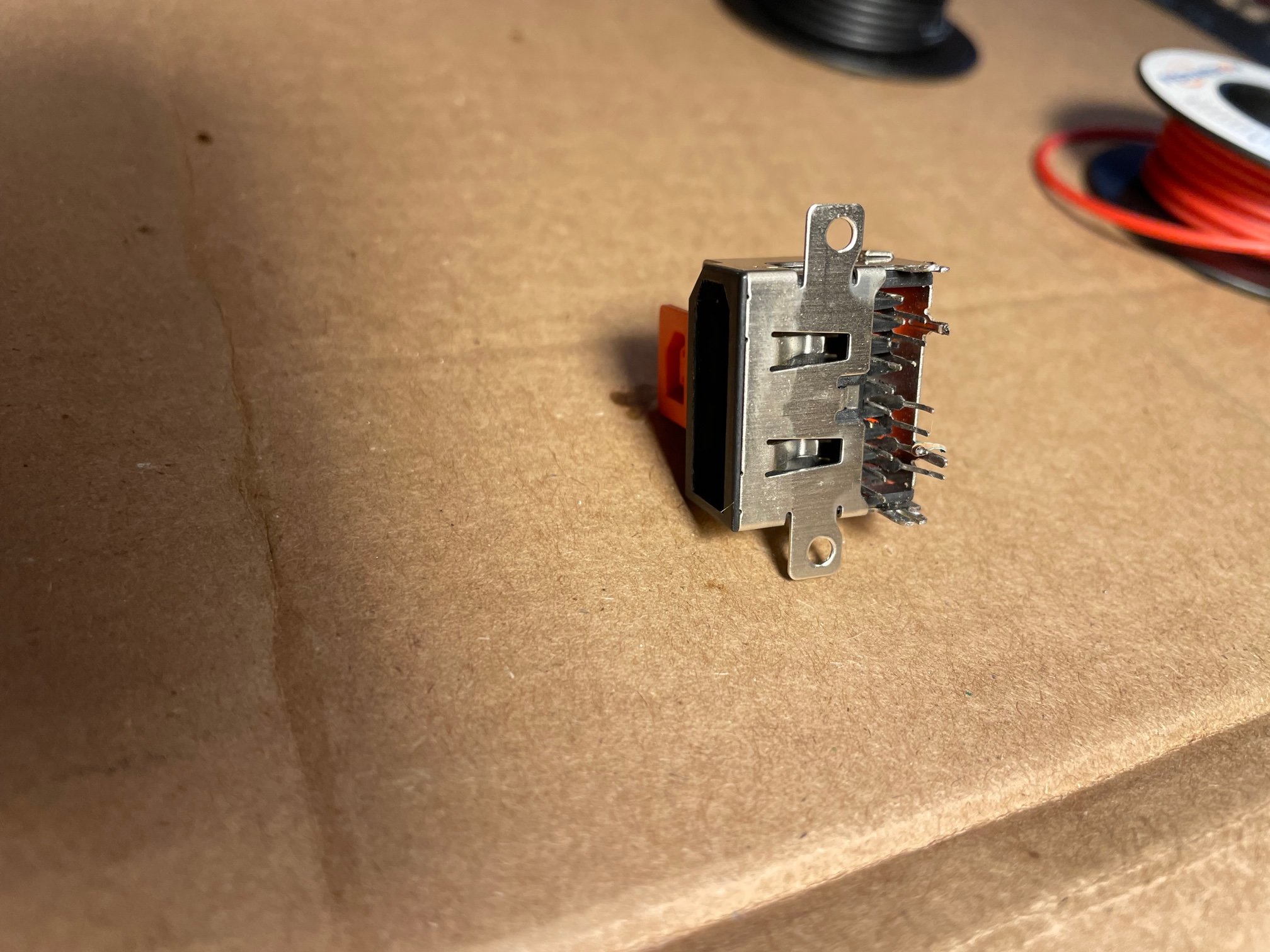
  5. I have trimmed the wii but havent tested it yet because I wasnt sure how to charge the batteries without hooking them up to the PMS and PD first. I am hoping to do an MX and bluetooth relocation. I also desoldered the AV connector on the wii to use for testing and I did Not anticipate that being so challenging but I got it. I checked the resistances on the wii and those are shown below. I think they're in reasonable range? I also removed the LDO but the dremel did go lower than I meant to and sliced the board a bit, unclear if that will be an issue or not.
Wii Trim Resistances.png
IMG_5970.jpg
IMG_5971.jpg
IMG_5972.jpg


THE PROGRESS
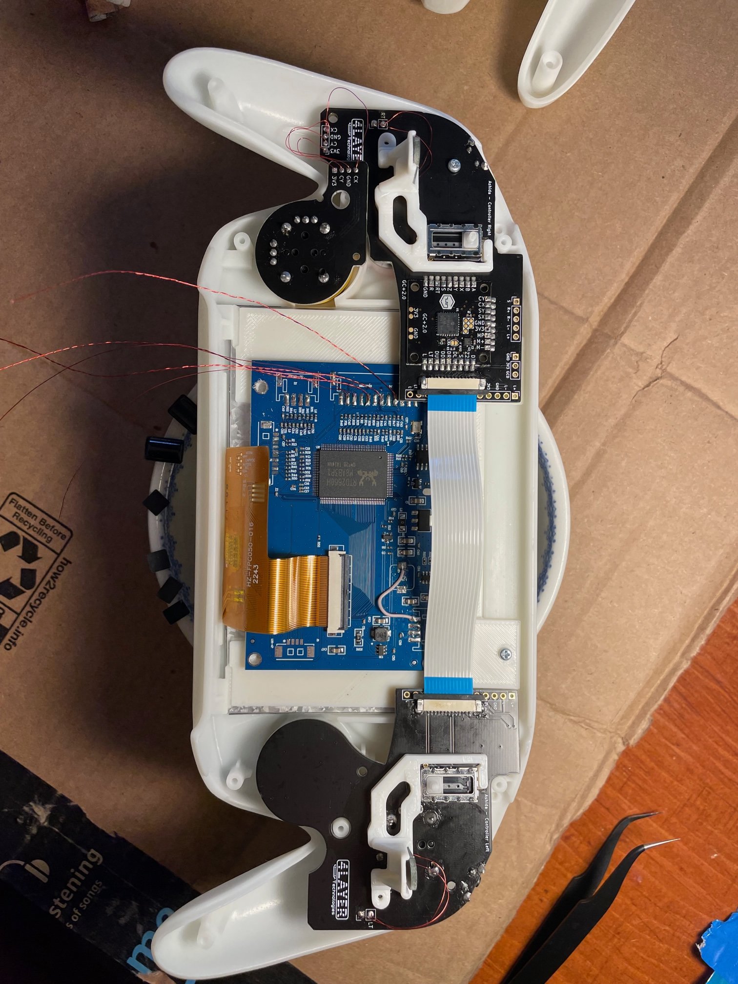
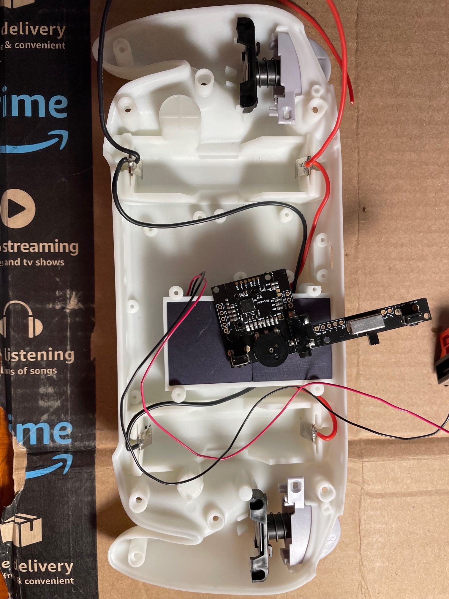
  1. So far I have plopped the triggers, battery clips, heat sink and fan in and populated all the boards.
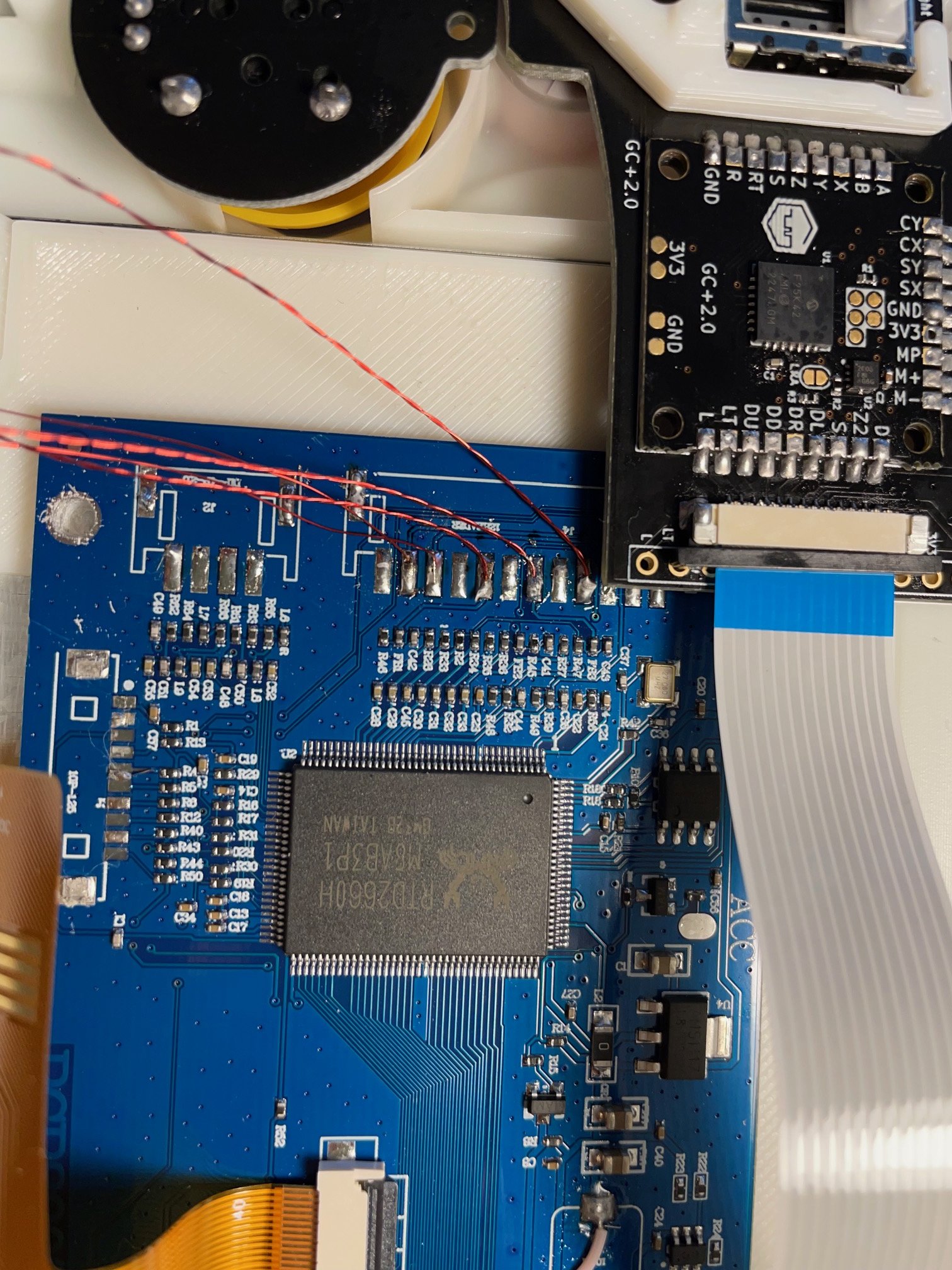
  2. I desoldered all the connectors on the driver board and ran a 30awg wire from the inductor to ground like how 4layer said to. I did end up ripping up some traces on one of the connectors (not the VGA one thank god) but Idk if that will cause a short or not.
  3. I used the mounting bracket and fixed in the IPS screen with the driver board behind it. I then twisted 34awg magnet wire for the red, blue, and green lines and used untwisted 34awg wire for the Hsync and Vsync.
  4. I then soldered on the ribbon cable connectors hopefully well (that was a little tricky) and soldered on the GC+ 2 in hopefully the correct orientation. I can 34awg wire to the trigger stops and the c-stick box (not sure if I made the wires to the C-stick box too long or not)
  5. Then I used the screws and bolted down everything along with the trigger stop mounts and connected the ribbon cable between the two halves.
  6. I soldered 20awg between the battery clips and that is as far as I got as of July 20, 2023.
IMG_5964.jpg
IMG_6049.jpg
IMG_6047.jpg
IMG_6050.jpg

IMG_6048.jpg
IMG_5966.jpg

NEXT STEPS:
  1. I need to order thermal pads for the heatsinks because I forgot those
  2. I am waiting on the buttons for the populated amp board because I forgot those when I ordered all the stuff from PCBway
  3. Then I am hoping to get that nailed down and wire it up to the PMS and then PMS to PD and the batteries in place and charge those puppies up so I can test
  4. Then testing
QUESTIONS:
  1. Do we think that slice next to the LDO will be a problem and are those resistances for the wii acceptable?
  2. Is the my method of charging the batteries going to be okay?
  3. Did I ruin the drive board by ripping up that trace?
  4. Are the wires for the c-stick too long?
  5. Are the GC+ and RVL-AMP in the correct orientation?

Thank you for any and all help I appreciate it! I tried to do as much of my own research as possible before starting this thread and asking questions but I apologize if any q's I have are dumb or already answered somewhere I failed to look.
 

Attachments

Viilmo

.
Joined
Jun 23, 2021
Messages
208
Likes
92
Location
Germany
Portables
1
The board slice might be a problem since 1v8 resistance is too low.
Remove all components you have on the side that you sliced through as they could also be causing a short.
 

Stitches

2 and a Half Dollarydoos
Staff member
.
.
Joined
Feb 5, 2017
Messages
3,848
Likes
3,026
Location
Banana Bender Land, Australia
Portables
6
8ohms from 1.8v to ground is way too low, probly got a transient short. I'd do as Viilmo said, and also take a knife and scrape away the material between all the LDO pads. If those copper flakes aren't causing the short I'll be very surprised
1689988520526.png
 
Joined
Jul 20, 2023
Messages
17
Likes
5
So I have been trying to get wii trims to work. I realized in my initial post of the wii resistance values that I posted the values of the trim before I nicked the board removing the LDO. The values after the LDO nick are posted below. They are way lower than they should be and I don't quite know how to fix a short on the slice (if anyone has any advice on that that would be excellent.
first wii trim after slice.png


After I realized that I got a new wii and attempted a second trim it went a little better, I should've used a heat gun instead of the dremel to remove LDO as I did end up slightly nicking the board again and I tested my resistances and they were slightly better but still low so I removed some sliced components and somehow made the resistances worse (like down to under 1k for the 3.3V tests), attempted to sand again, still no change so I trimmed a little bit father in as my first trim was kind of big and sanded again and the resistances are still pretty low
Screenshot 2023-08-04 115946.png

These are the pictures of the first trim:
wii 1 trim closer.jpg
wii 1 trim.jpg

these are the pictures of the second trim:
wii2 trim front.jpg
wii2 trim back.jpg
wii2 trim front closeup.jpg

I ordered another wii to attempt the trim again because I am at a bit of a loss on how to fix these.
 
Joined
Jul 20, 2023
Messages
17
Likes
5
I have trimmed the third wii, defiinitely a short somewhere because resistance check is giving 0
3rd trim back.jpg
3rd trim front.jpg
3rd trim edge3.jpg
3rd trim edge1.jpg
3rd trim edge2.jpg
 

Stitches

2 and a Half Dollarydoos
Staff member
.
.
Joined
Feb 5, 2017
Messages
3,848
Likes
3,026
Location
Banana Bender Land, Australia
Portables
6
There are a few components along the trim line that you have cut through. Those components can cause shorts and need to be removed. The 5 round electrolytic capacitors also need to be removed since you've damaged them quite badly
 
Joined
Jul 20, 2023
Messages
17
Likes
5
Okay so I have wired everything up, shout out to @CrazyGadget for help getting my trim to work and the relocations. Everything is together, I turned it on with just the batteries and fan and the fan turned on and stayed on which was cool. After wiring up everything, I attempted to turn things on and the fan came on for a second and then shut down. I checked resistances on the wii motherboard and somewhere there is a short with 3.3V, I don't know where it is and was wondering if anyone had any ideas. Build is pictured below. Any help is greatly appreciated. I used 20awg wire for all voltage wires to wii and kept the U10 relocation that Crazy Gadget did.
IMG_6346.jpg
IMG_6347.jpg
IMG_6348.jpg
IMG_6349.jpg
IMG_6350.jpg
IMG_6351.jpg
IMG_6355.jpeg
IMG_6356.jpeg
 
Last edited:
Joined
Jul 20, 2023
Messages
17
Likes
5
There are a few components along the trim line that you have cut through. Those components can cause shorts and need to be removed. The 5 round electrolytic capacitors also need to be removed since you've damaged them quite badly
And thank you @Stitches , that was exactly the issue
 
Joined
Jul 20, 2023
Messages
17
Likes
5
So I got the wii to work and RVloader and all controls work!!! However, I have not tested audio yet and the fan only stays on for a second and then cuts out and makes a clicking sound like it is trying to move but it won't. Does anyone have any ideas? The fan ran fine when the wii wasnt hooked up to the PMS . Audio is also not working
IMG_6380.jpeg
IMG_6379.jpeg
 
Last edited:

Stitches

2 and a Half Dollarydoos
Staff member
.
.
Joined
Feb 5, 2017
Messages
3,848
Likes
3,026
Location
Banana Bender Land, Australia
Portables
6
I'm guessing you're using i2c audio?
 
Joined
Jul 20, 2023
Messages
17
Likes
5
I'm guessing you're using i2c audio?
I believe so? I am using an RVLamp and I wired SDW and SCW to pms, ashida board and wii and wired MC twisted with ground, D, C, and WS from ashida board directly to the corresponding vias on the wii.

Audio is staticy (only static really) on headphones and speakers, volume control works fine and the speakers are soldered to the contacts
 

Stitches

2 and a Half Dollarydoos
Staff member
.
.
Joined
Feb 5, 2017
Messages
3,848
Likes
3,026
Location
Banana Bender Land, Australia
Portables
6
I believe so? I am using an RVLamp and I wired SDW and SCW to pms, ashida board and wii and wired MC twisted with ground, D, C, and WS from ashida board directly to the corresponding vias on the wii.

Audio is staticy (only static really) on headphones and speakers, volume control works fine and the speakers are soldered to the contacts
Are you able to shorten the wires at all?
 
Joined
Jul 20, 2023
Messages
17
Likes
5
Yeah I probably can, I just switched the MC wire from a 34awg magnet wire twist with 34 awg gnd wire to a wifi shielded wire from the wii and I am still getting only static. Do you think shortening would help? or tacton taping the audio lines together to help shielding?
 

Stitches

2 and a Half Dollarydoos
Staff member
.
.
Joined
Feb 5, 2017
Messages
3,848
Likes
3,026
Location
Banana Bender Land, Australia
Portables
6
I don't know if taping the i2c lines together would help with that, but it probably won't hurt to try. Wire length is a common source of trouble, so I'd try shortening them first tho
 
Joined
Jul 20, 2023
Messages
17
Likes
5
I don't know if taping the i2c lines together would help with that, but it probably won't hurt to try. Wire length is a common source of trouble, so I'd try shortening them first tho
So I shortened all the audio lines and reattached them and now I have a new problem. The fan, the LED and the screen all turn on and the wii gets hot so I assume there is power but nothing shows up on screen it is just black. No rvloader, not boot error message nothing. All the video lines are as connected as there were earlier and mode is still wired up, I dont know why nothing is showing up
 
Joined
Jun 9, 2023
Messages
49
Likes
28
Portables
2
Try wiring composite and make sure your u10 is solid. Also make sure to clean near the scw and sdw pads on the pms and everything else in general.
 
Top