- Joined
- May 10, 2019
- Messages
- 23
- Likes
- 15
Hi everyone! I recently got this new 7 inches screen, and right out of the box I tried running it with 5 v before modding. It did run, but the screen quality was lower than it was when running with 12V, very noticeable (Using a variable power supply helps a lot when testing these) and all the controls buttons from the screen were not working when using 5v (Power, menu, up and down, etc) just the contrast button was ´partially working but on the video selection button instead of it's right button.
I mapped some of it's voltage points but it's a tad confusing to me where I should inject 5v or what I should remove, because I'm getting some crazy readings here... (All tested with 12V supplied)
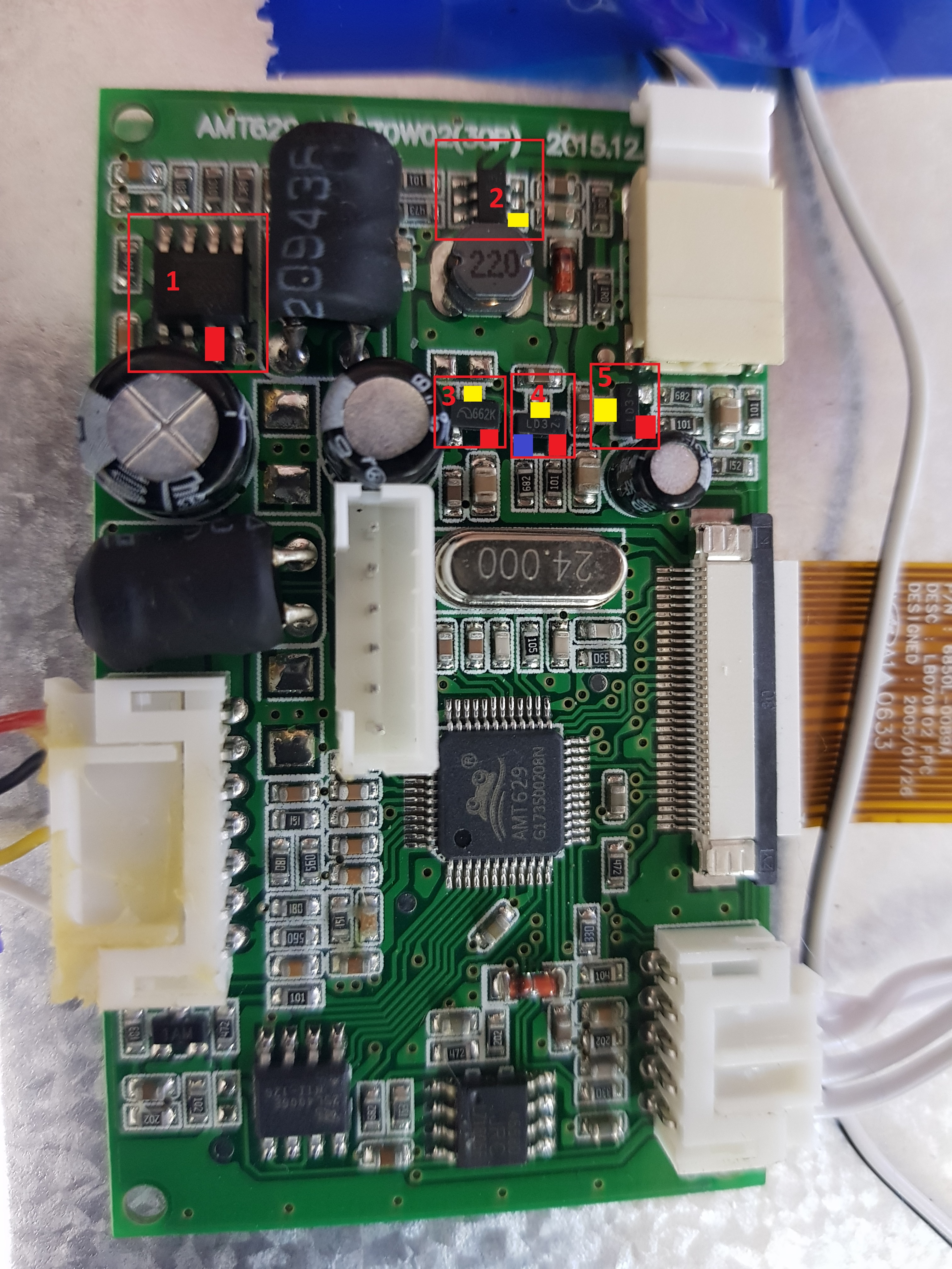
In order as I labelled them.:
1 - MP 1482 https://www.monolithicpower.com/pub/media/document/MP1482_r1.31.pdf
As the file says "The MP1482 is a monolithic synchronous buck regulator."
On point 3, as marked, it's output is + 5V
2 - PT4103 http://www.micro-bridge.com/data/CRpowtech/PT4103E.pdf
It says there "The PT4103 is a step-up DC/DC converter", I hope I got the right datasheet here, but it checks out, on pin one the output is + 5V as well.
3 - 662K voltage regulator (Didn't find this specific datasheet)
Yellow pin = +5V,
Red pin = +3.3v
(What I did find is that these 662K are 3.3v regulators so this checks out,
nothing to do here)
4 - LD3 (N? or Z? couldn't find anything about this one, nothing but a seller on aliexpress, with no description for it, but my guess it's also a voltage regulator?)
Yellow pin = + 9.3V
Blue pin: = + 5V
Red Pin: = + 14V
5- LD3 (N? or Z?)
Yellow pin = - 5 V
Red pin = - 8,5V
(Yup, they are negative)
So, should I just input 5v to that first IC's output? Tried that, did not work.
I mapped some of it's voltage points but it's a tad confusing to me where I should inject 5v or what I should remove, because I'm getting some crazy readings here... (All tested with 12V supplied)
In order as I labelled them.:
1 - MP 1482 https://www.monolithicpower.com/pub/media/document/MP1482_r1.31.pdf
As the file says "The MP1482 is a monolithic synchronous buck regulator."
On point 3, as marked, it's output is + 5V
2 - PT4103 http://www.micro-bridge.com/data/CRpowtech/PT4103E.pdf
It says there "The PT4103 is a step-up DC/DC converter", I hope I got the right datasheet here, but it checks out, on pin one the output is + 5V as well.
3 - 662K voltage regulator (Didn't find this specific datasheet)
Yellow pin = +5V,
Red pin = +3.3v
(What I did find is that these 662K are 3.3v regulators so this checks out,
nothing to do here)
4 - LD3 (N? or Z? couldn't find anything about this one, nothing but a seller on aliexpress, with no description for it, but my guess it's also a voltage regulator?)
Yellow pin = + 9.3V
Blue pin: = + 5V
Red Pin: = + 14V
5- LD3 (N? or Z?)
Yellow pin = - 5 V
Red pin = - 8,5V
(Yup, they are negative)
So, should I just input 5v to that first IC's output? Tried that, did not work.
Last edited: