Question IPS Driver Board 3.3 Short and Fan Issue

Joined
Jan 6, 2024
Messages
22
Likes
2
These are two unrelated issues.

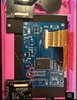
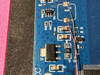
Almost done assembling my Ashida and I was getting a short between 3.3 and ground so I started disconnecting my 3.3 connections and I realize its coming through the IPS driver board. On the board itself I am getting a short from 3.3 to ground even when it’s not connected to anything. As soon as I disconnected it I stopped getting the short in the rest of the Wii. Tried multiple different ground locations on the board. Did I damage something removing components?

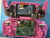
After my last post where I successfully tested the composite signal the fan was running differently than it had in any prior tests. Normally turning the system on the fan would just run. This time it ran for a second and then slowed way down it sounded like it was clicking. Now if I have a battery in at all even with the switch off, the fan clicks. However if I disconnect the T- wire from the RVL-NTC the fan runs as normal. I was going to continue my assembly to see if the fan just needed to be adjusted in the system settings but figured I’d throw this in to see if anyone had any insight.
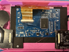
tempImageysSfKB.pngtempImageSmo32E.png
 

Stitches

2 and a Half Dollarydoos
Staff member
.
.
.
Joined
Feb 5, 2017
Messages
3,874
Likes
3,049
Location
Banana Bender Land, Australia
Portables
6
Not sure about the fan, but I can't see any visual indication of a short on the driver board
 
Joined
Jan 4, 2023
Messages
71
Likes
24
Is there any particular reason you’re grounding the board to there instead of following the 4layertech instructions?
 

Attachments

Joined
Jan 4, 2023
Messages
71
Likes
24
Also, it’s a good habit to use kapton tape on the bottom side of the right Ashida PCB to prevent the vias from potentially coming in contact with the RGB lines.
 
Joined
Jan 6, 2024
Messages
22
Likes
2
There is nothing grounded to that in the photo. That is a wire I have disconnected in my hunt for the 3.3 short. It must be just hanging out above that. Nothing was touching the IPS driver board when I was testing for continuity between 3.3 and ground.

I did not put put kapton tape on the bottom of that Ashida PCB but I just tried move it to make sure nothing was interfering and there was no change.

I am getting a resistance reading of .2 ohms.
 

Stitches

2 and a Half Dollarydoos
Staff member
.
.
.
Joined
Feb 5, 2017
Messages
3,874
Likes
3,049
Location
Banana Bender Land, Australia
Portables
6
Is there any particular reason you’re grounding the board to there instead of following the 4layertech instructions?
The GND location really doesn't matter much, they're all internally connected. The GND location marked in the doc is just a beginner friendly spot to solder to that doesn't have anything important right next to it to accidentally bump or damage.

There is nothing grounded to that in the photo. That is a wire I have disconnected in my hunt for the 3.3 short. It must be just hanging out above that. Nothing was touching the IPS driver board when I was testing for continuity between 3.3 and ground.

I did not put put kapton tape on the bottom of that Ashida PCB but I just tried move it to make sure nothing was interfering and there was no change.

I am getting a resistance reading of .2 ohms.
0.2 ohms is definitely a short. Question is where.......... Have you verified that the short is still present with the LCD ribbon cable unplugged? Might also be worth using a magnifying glass/microscope to examine the pads and passives near anywhere that you've soldered to check for blobs or solder wisps that might be too small to show up in these photos.
 
Joined
Jan 6, 2024
Messages
22
Likes
2
So frustrating.. unplugged the ribbon and went over again with the magnifying glass. I'm seeing nothing. Would the next step just be purchasing another?
 

Stitches

2 and a Half Dollarydoos
Staff member
.
.
.
Joined
Feb 5, 2017
Messages
3,874
Likes
3,049
Location
Banana Bender Land, Australia
Portables
6
Potentially. How did you remove the inductor? Hot air or iron?
 

Stitches

2 and a Half Dollarydoos
Staff member
.
.
.
Joined
Feb 5, 2017
Messages
3,874
Likes
3,049
Location
Banana Bender Land, Australia
Portables
6
Hmmm. Can you check C40, right by the removed inductor? There's a funny reflective line there that might be a solder bridge caused by bumping the capacitor during inductor removal

1714980524141.png
 

Stitches

2 and a Half Dollarydoos
Staff member
.
.
.
Joined
Feb 5, 2017
Messages
3,874
Likes
3,049
Location
Banana Bender Land, Australia
Portables
6
It was the other side of the caps, but yeah it might just have been a digital artefact
 
Top