- Joined
- Jan 16, 2016
- Messages
- 1,525
- Likes
- 4,064
- Location
- standing up
- Portables
- please do not ask!!!! I will NOT respond
With the surge of completed LMAO trims, I'm releasing some of my notes from my personal compendium.
If you're new to Wii portablizing or don't have finely developed soldering skill, you may want to skip this relocation, as it's a sharp increase in difficulty compared to the other relocations, for a very minimal gain in motherboard profile.
Removing the NAND, LDO, and the supporting caps and resistors before trimming is highly recommended. Tape them to a sheet of paper and write down the matching silkscreen text, so you know exactly what's what.
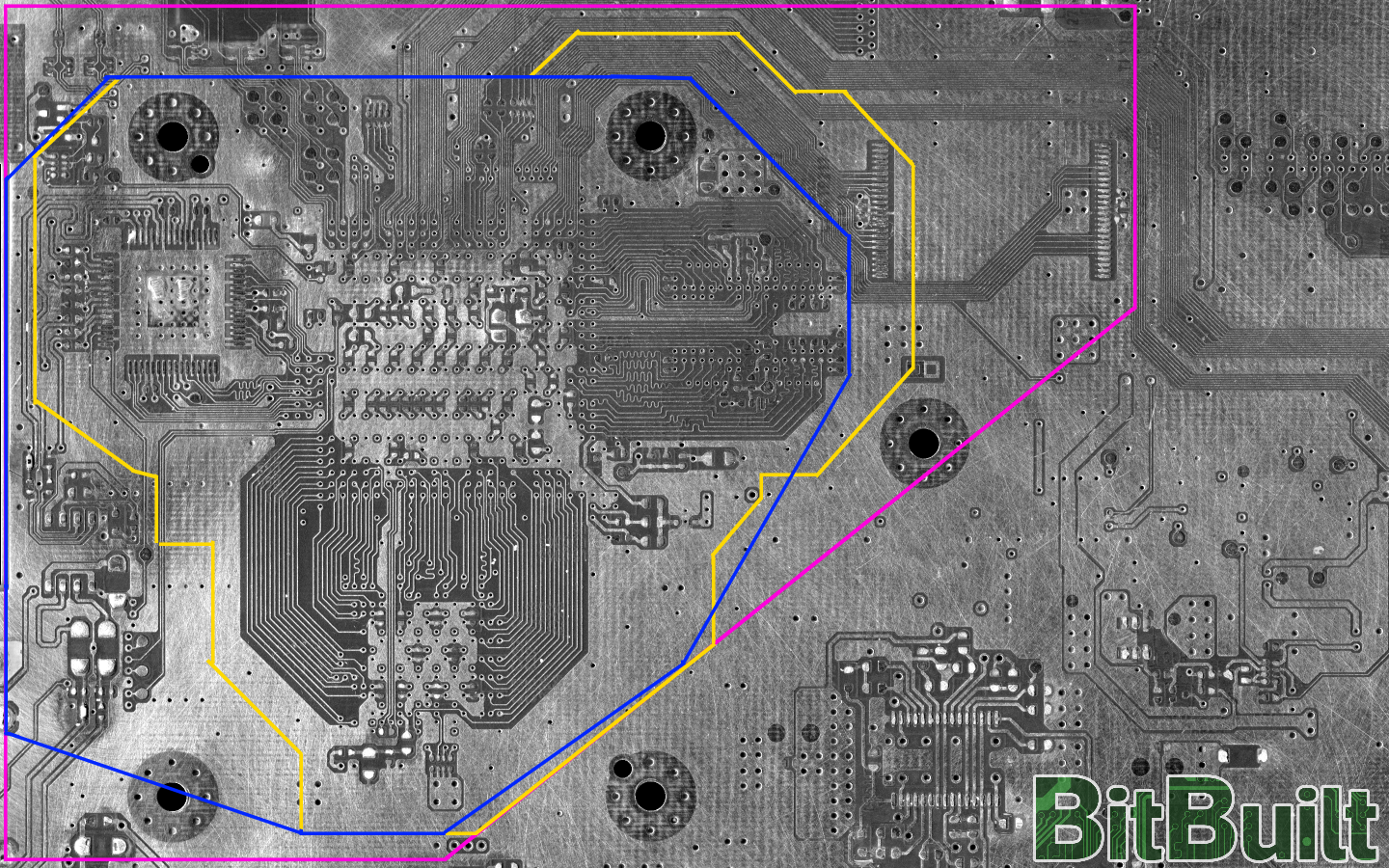
We've got 3 colored lines here that represent 3 different trims:
Pink - OMGWTF:
This is the standard trim outlined in The Definitive Wii Trimming Guide, and the most popular due to it's relative ease. No NAND rewiring is required.
Yellow - LMAO:
This trim was developed as a concept, before taking a practical look at defining a shape. Lots of inward cuts make it more difficult, so this is for the more ambitious trimmers. Pay special attention to the right side of the trim, closer inspection will reveal that it intentionally leaves the traces for one side of the NAND intact. This allows careful removal and resoldering to perform a "NAND bend," where the pins are bent downward so that they can be resoldered to the pads.
Blue - LMAOv2:
This trim is a more developed trim, allowing a broader, bolder outline without inward cuts. This makes it easier to perform, but comes at a cost; wiring both sides of the NAND. This has only been done with the use of breakout boards, and is not recommended to be done by hand. In addition, it keeps the preamp intact.
NOTE: When trimming it is possible to sever the internal 3.3v trace that provides power to our alternate U10 relocation spot. This will prevent the Wii from booting, so always check if this must be reconnected.
Trims:

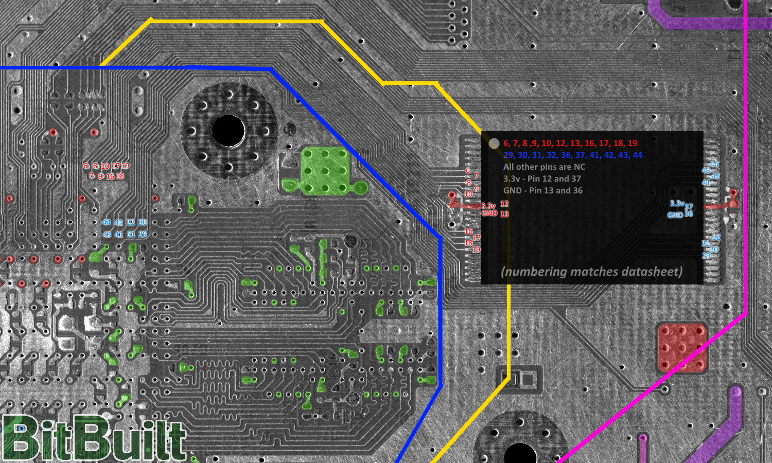
Moving onto the connections. These are fairly straightforward. Each side of the NAND has different colored numbers. 34 gauge wire works well here. These wires should be as short as possible (and I mean, as short as possible) to avoid issues. In addition, the 3.3v capacitors should be preserved.
If you're performing a NAND bend, you may need to remove the larger capacitor near the heatsink mounting hole. This can be relocated nearby with wire, or to the other side of the board.
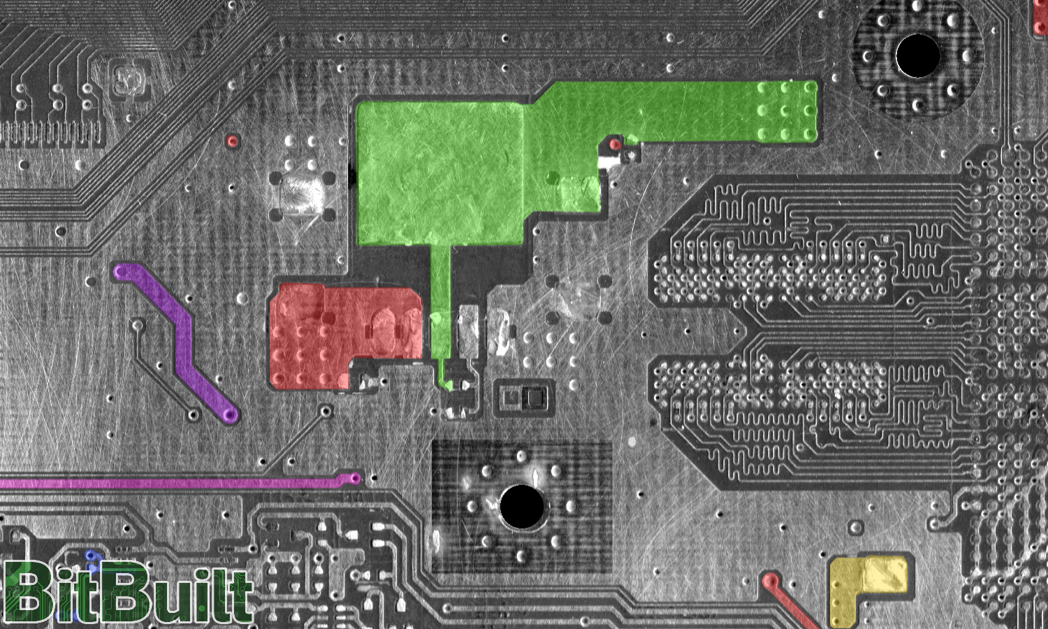
3.3v is filled in red, and 1.8v is green.
The LDO will also have to be relocated when performing these trims. It requires the two resistors to set the voltage, these can be reconnected by studying the image below.
Connect a 1.2k resistor between pins 3 and 4, and a 2.7k resistor between pin 4 and ground.
Connections:


If you're new to Wii portablizing or don't have finely developed soldering skill, you may want to skip this relocation, as it's a sharp increase in difficulty compared to the other relocations, for a very minimal gain in motherboard profile.
Removing the NAND, LDO, and the supporting caps and resistors before trimming is highly recommended. Tape them to a sheet of paper and write down the matching silkscreen text, so you know exactly what's what.
We've got 3 colored lines here that represent 3 different trims:
Pink - OMGWTF:
This is the standard trim outlined in The Definitive Wii Trimming Guide, and the most popular due to it's relative ease. No NAND rewiring is required.
Yellow - LMAO:
This trim was developed as a concept, before taking a practical look at defining a shape. Lots of inward cuts make it more difficult, so this is for the more ambitious trimmers. Pay special attention to the right side of the trim, closer inspection will reveal that it intentionally leaves the traces for one side of the NAND intact. This allows careful removal and resoldering to perform a "NAND bend," where the pins are bent downward so that they can be resoldered to the pads.
Blue - LMAOv2:
This trim is a more developed trim, allowing a broader, bolder outline without inward cuts. This makes it easier to perform, but comes at a cost; wiring both sides of the NAND. This has only been done with the use of breakout boards, and is not recommended to be done by hand. In addition, it keeps the preamp intact.
NOTE: When trimming it is possible to sever the internal 3.3v trace that provides power to our alternate U10 relocation spot. This will prevent the Wii from booting, so always check if this must be reconnected.
Trims:

Moving onto the connections. These are fairly straightforward. Each side of the NAND has different colored numbers. 34 gauge wire works well here. These wires should be as short as possible (and I mean, as short as possible) to avoid issues. In addition, the 3.3v capacitors should be preserved.
If you're performing a NAND bend, you may need to remove the larger capacitor near the heatsink mounting hole. This can be relocated nearby with wire, or to the other side of the board.
3.3v is filled in red, and 1.8v is green.
The LDO will also have to be relocated when performing these trims. It requires the two resistors to set the voltage, these can be reconnected by studying the image below.
Connect a 1.2k resistor between pins 3 and 4, and a 2.7k resistor between pin 4 and ground.
Connections:


Last edited:
