Jpin
.
- Joined
- Sep 17, 2021
- Messages
- 39
- Likes
- 24
Hello guys, after a long wait for the parts to arrive. Finally are here I’ll try to build a Louii portable so lot of work to do in the next days and by the way it’s my first project on electronics so don’t expect this post will develop fluid jejeje. here we go
For these first part here are the sparts I’m going to use. All PCB’s are from 4layer tech.
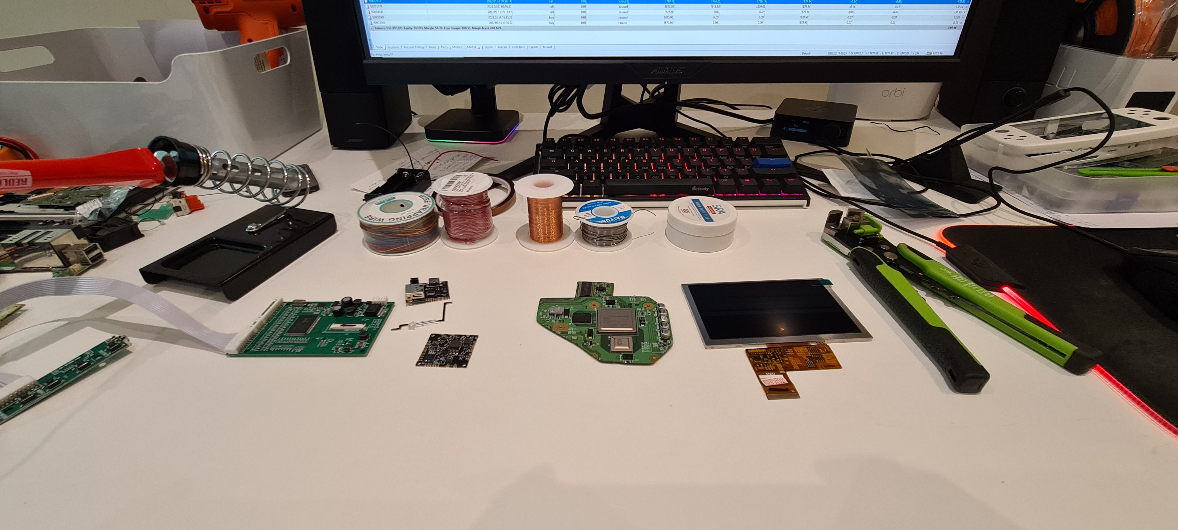
U10
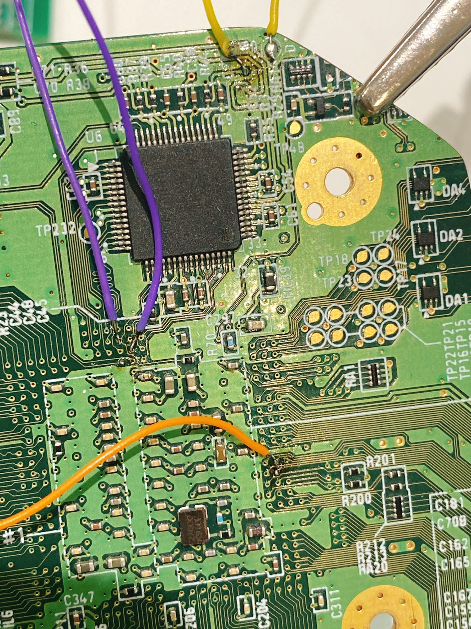
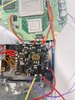
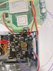
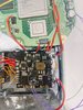
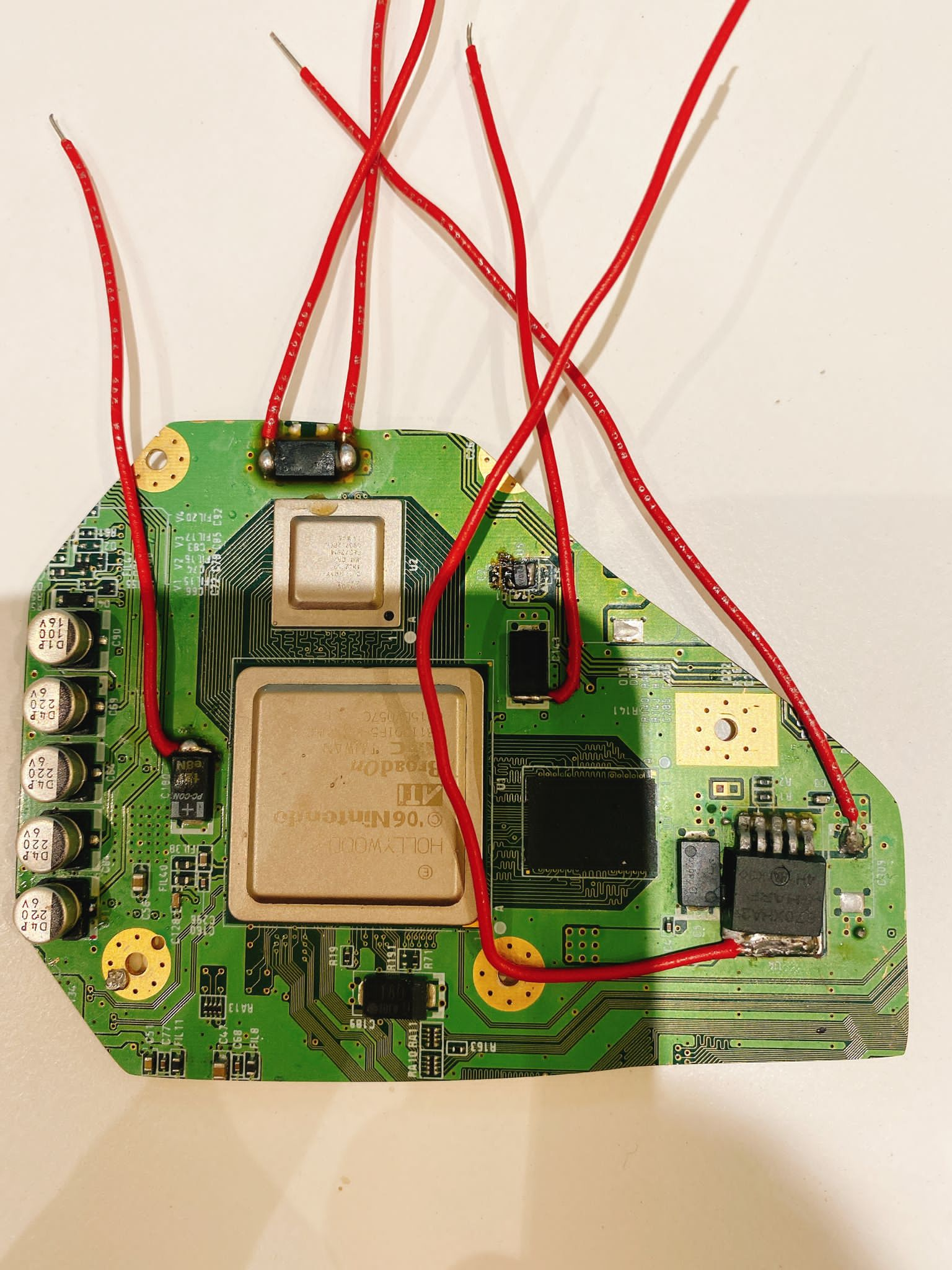
Start of the wiring, I try to measure the cable based on the case im going to use to have them ready once the first test goes well. Im using the RVL PMS LITE since the the version 2 is not available, also the U-amp2 and PMS-PD Revision B
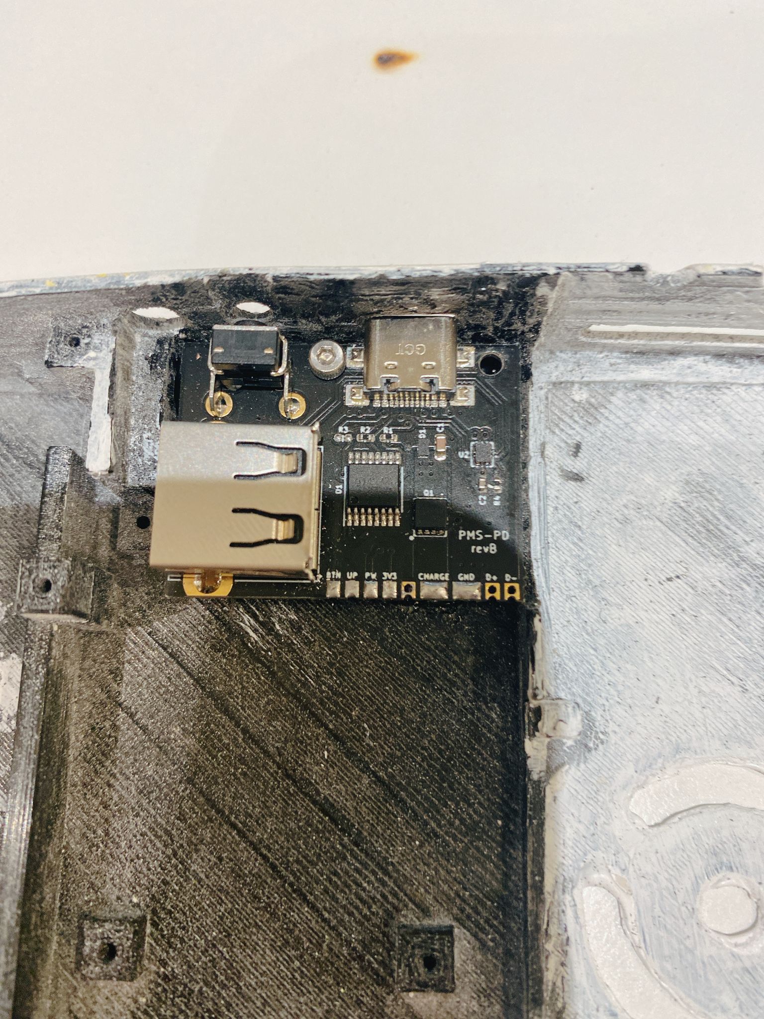
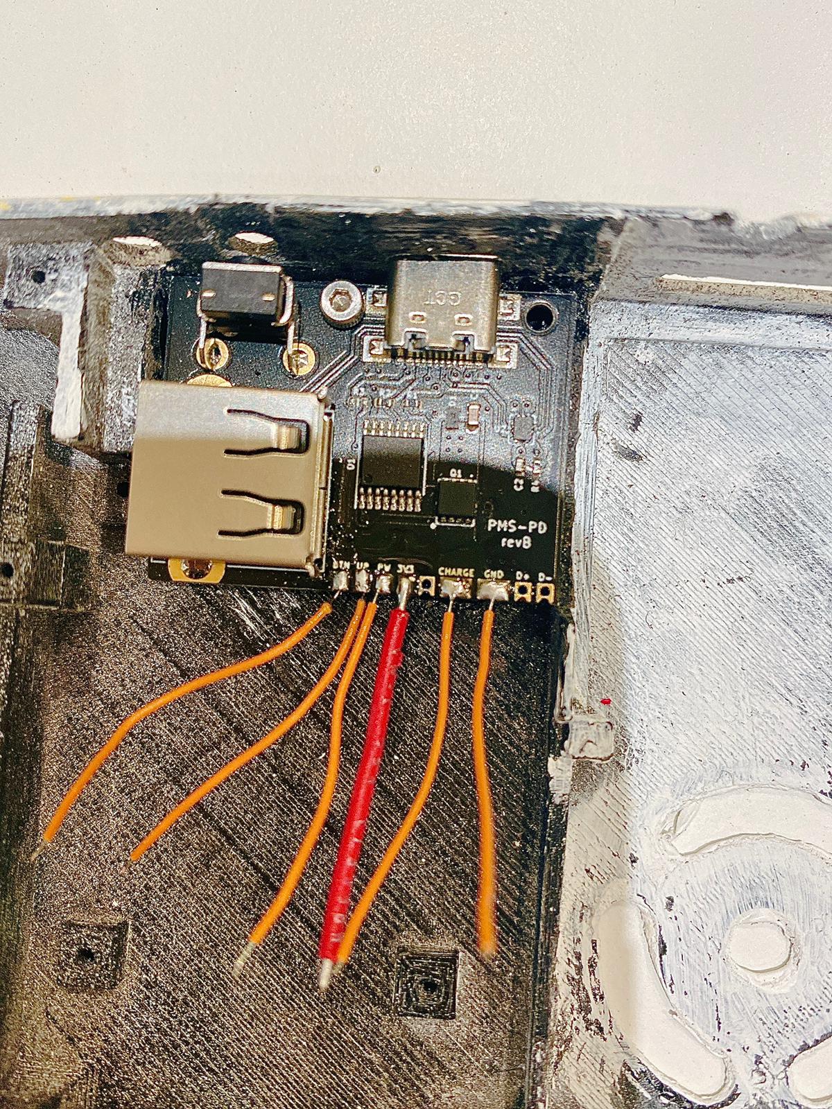
All this wiring I did was based on the diagram that you guys can find on the 4layertech web at documents on each product page.
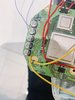
Now screen wiring, battery and time to do the first test.
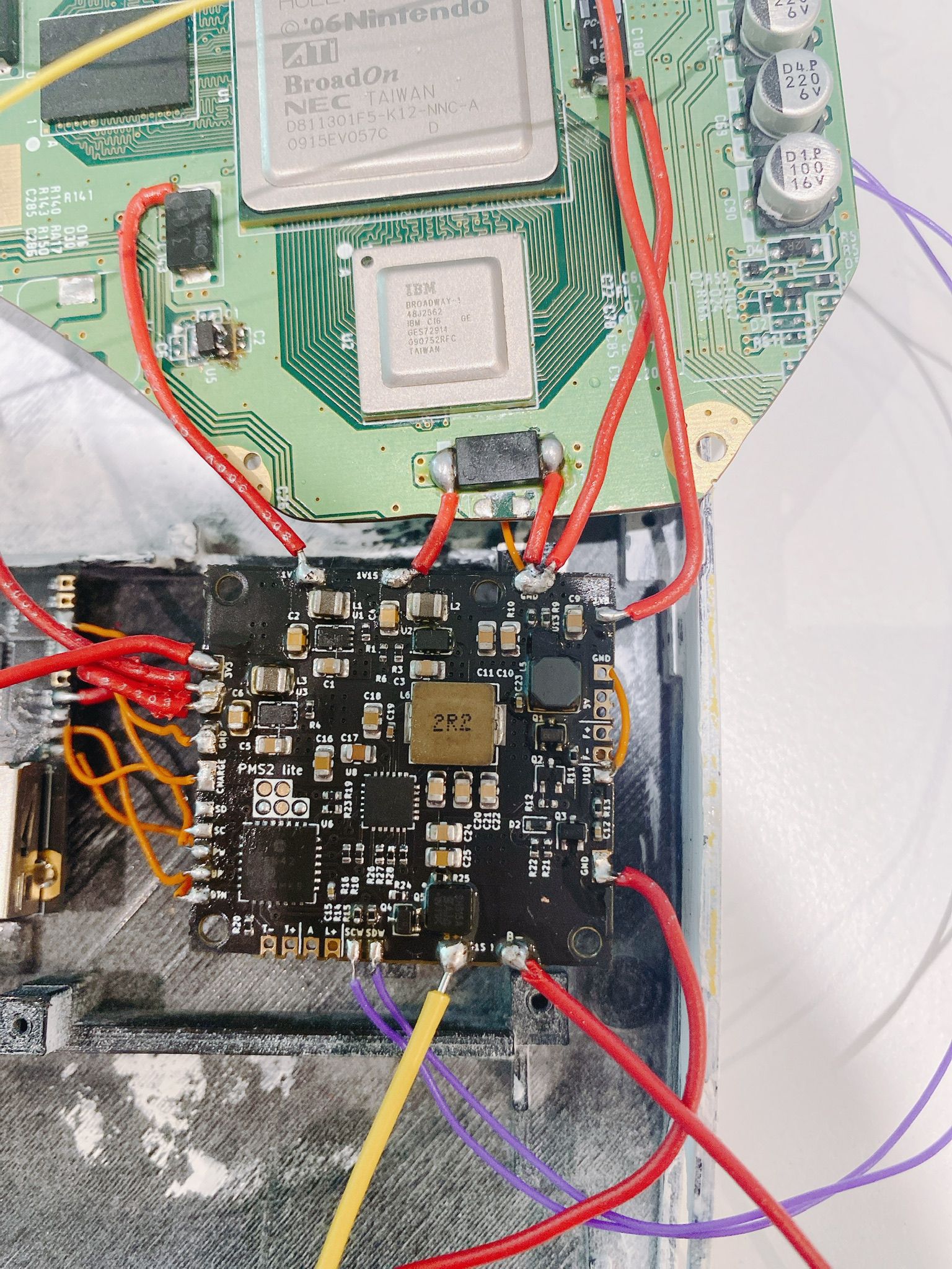
Ok so good and bad news as expected for a noob jejeje, the board doesn’t boot but the screen is working I didn’t fry it so not everything is bad. I just realize that the Lite board has a U10 connection, so I think I didn’t have to relocate the U10 and maybe that’s the reason is not working. Ill connect the U10 from the Lite and see how it turns for the moment this is my work progress.
For these first part here are the sparts I’m going to use. All PCB’s are from 4layer tech.
U10
Start of the wiring, I try to measure the cable based on the case im going to use to have them ready once the first test goes well. Im using the RVL PMS LITE since the the version 2 is not available, also the U-amp2 and PMS-PD Revision B
All this wiring I did was based on the diagram that you guys can find on the 4layertech web at documents on each product page.
Now screen wiring, battery and time to do the first test.
Ok so good and bad news as expected for a noob jejeje, the board doesn’t boot but the screen is working I didn’t fry it so not everything is bad. I just realize that the Lite board has a U10 connection, so I think I didn’t have to relocate the U10 and maybe that’s the reason is not working. Ill connect the U10 from the Lite and see how it turns for the moment this is my work progress.
Attachments
-
 602.2 KB Views: 98
 -
 715.6 KB Views: 97
 -
 382.3 KB Views: 102
 -
 451.6 KB Views: 97
Last edited: