
mcats
.
- Joined
- Mar 24, 2023
- Messages
- 13
- Likes
- 22
Hey everyone!
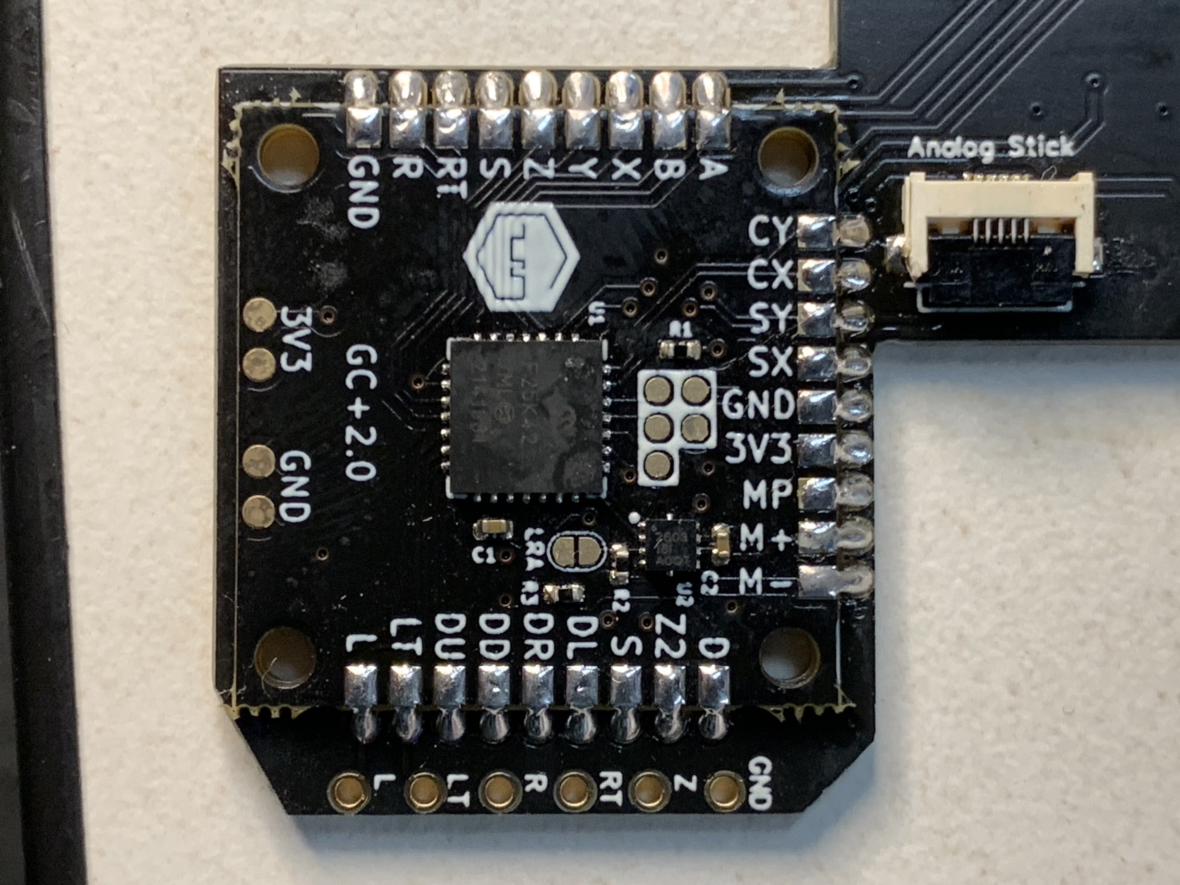
I recently started my journey of creating a G-boy. When the original Gboy kit came out, I desperately wanted to build one but didn't have the funds to at the time. Now with Gman's STLs, 4LayerTech, and Dustin Fisher's PCBs, I'm hoping to make one of my own!
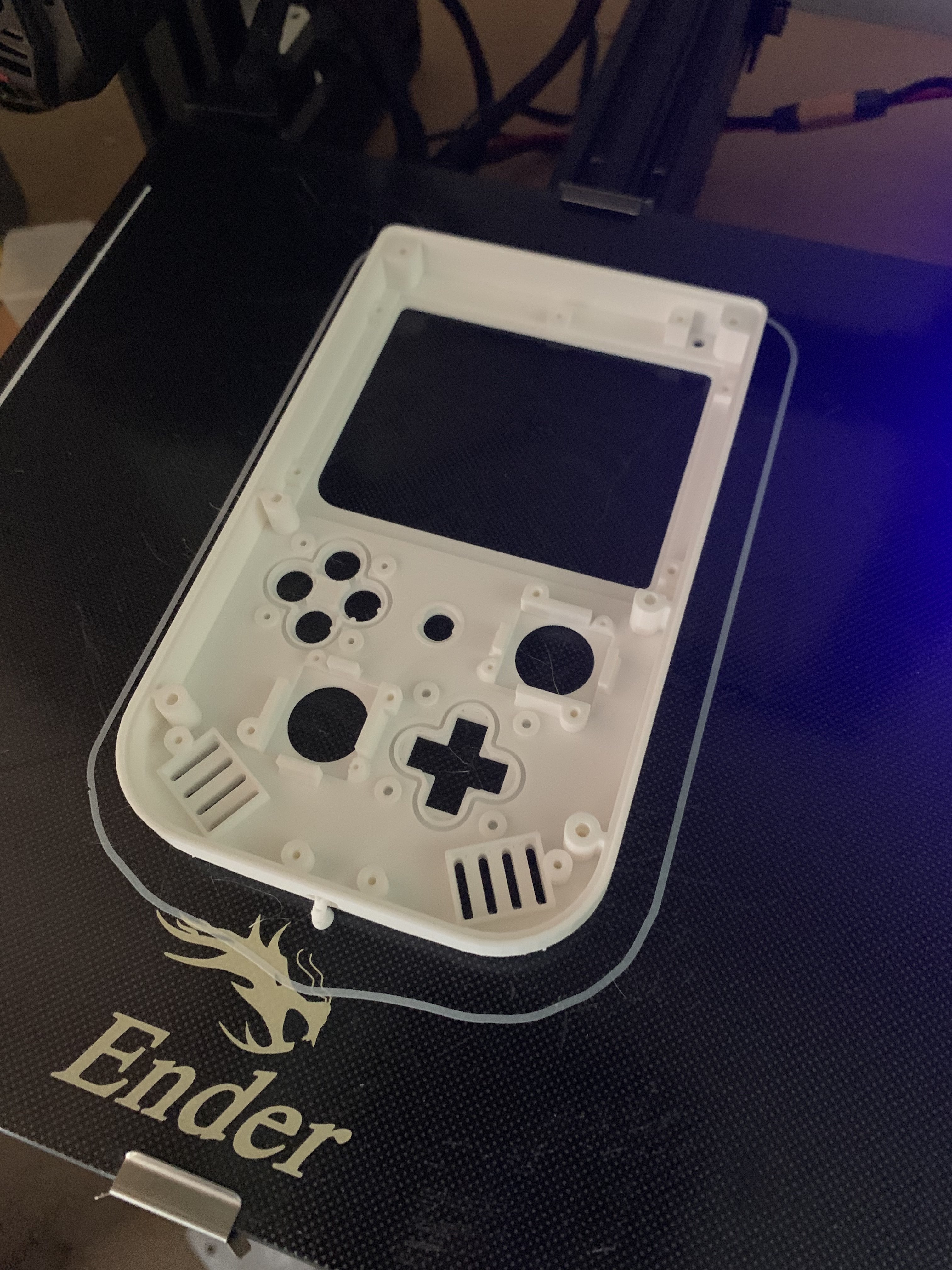
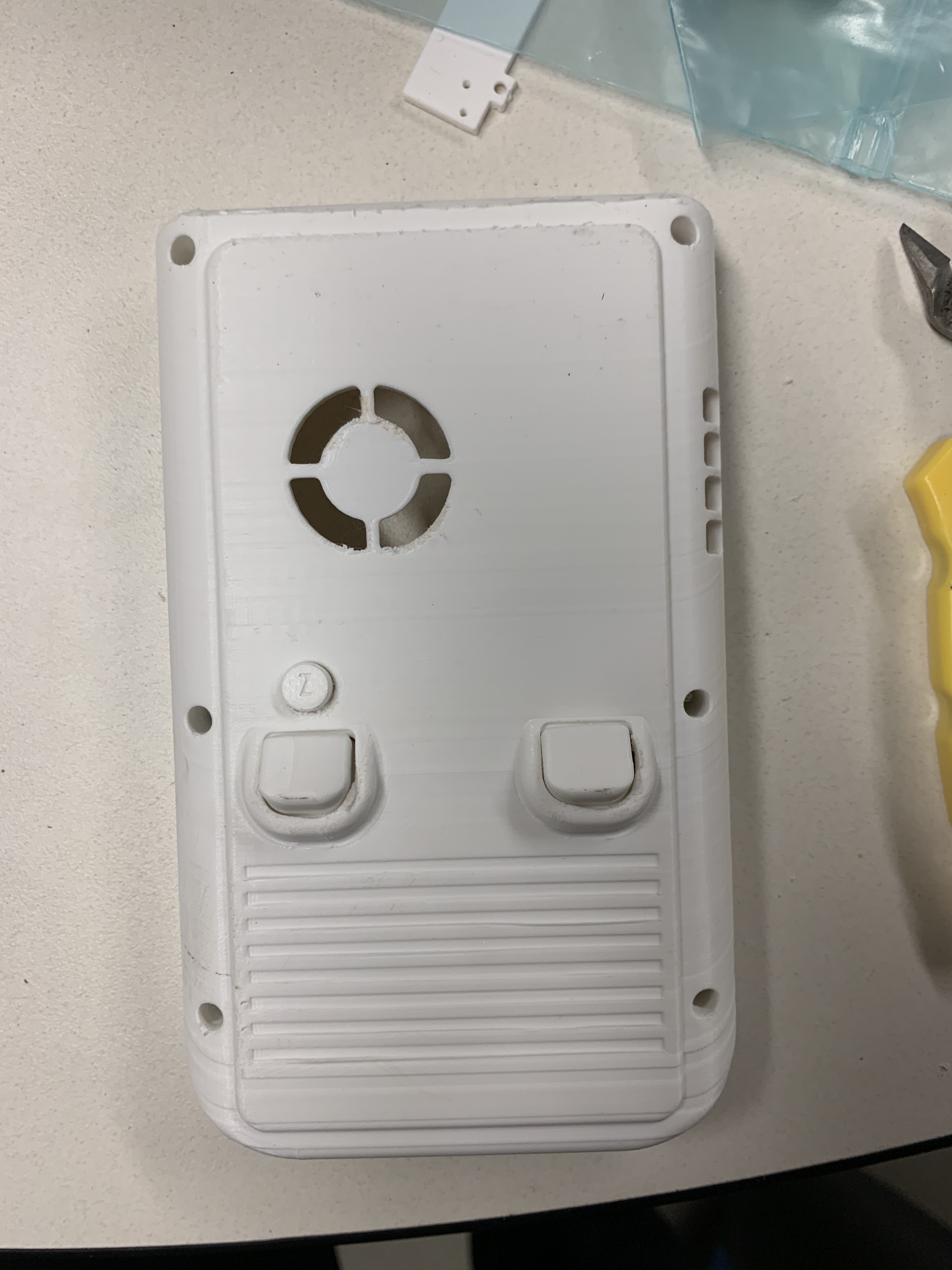
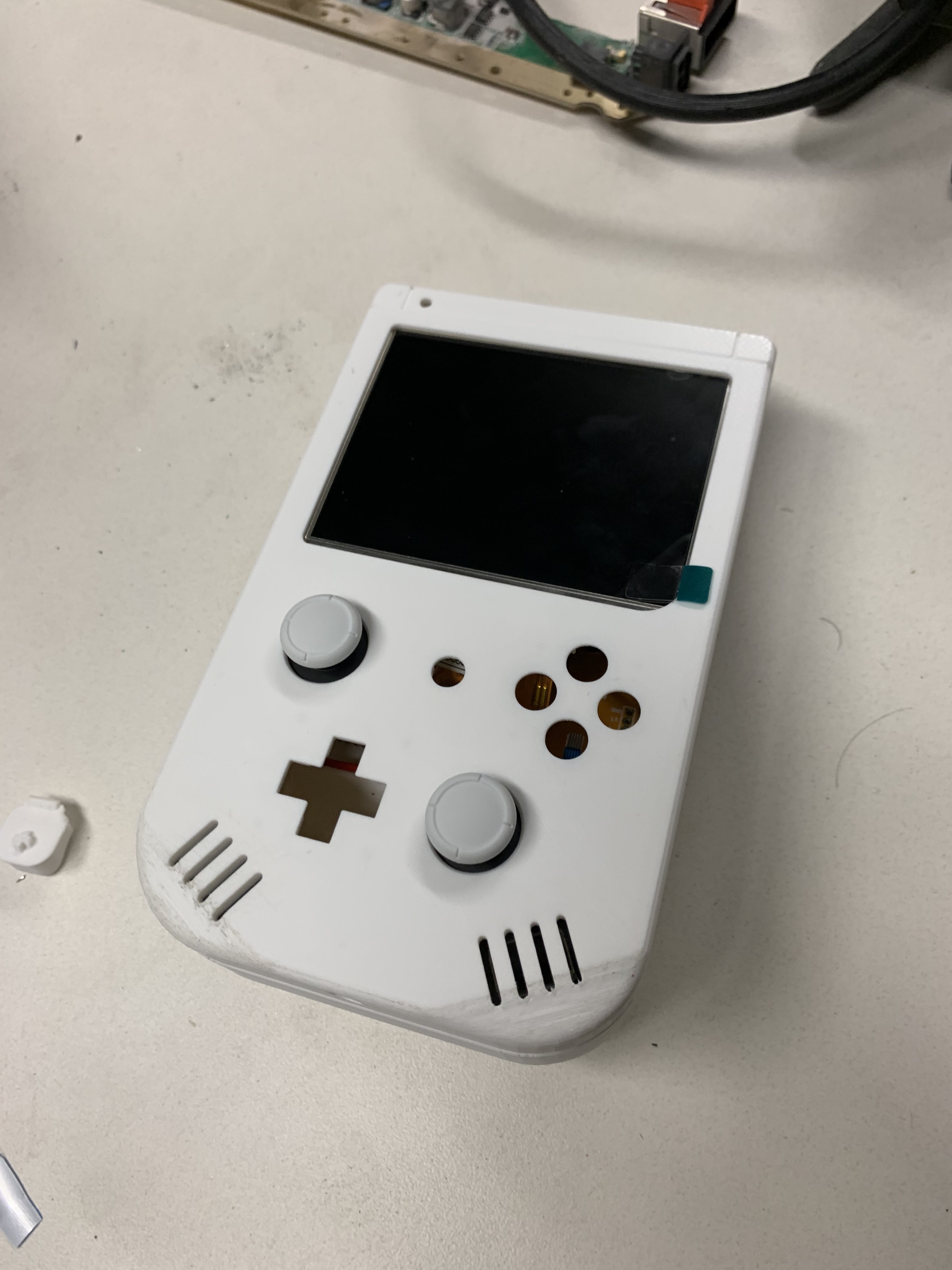
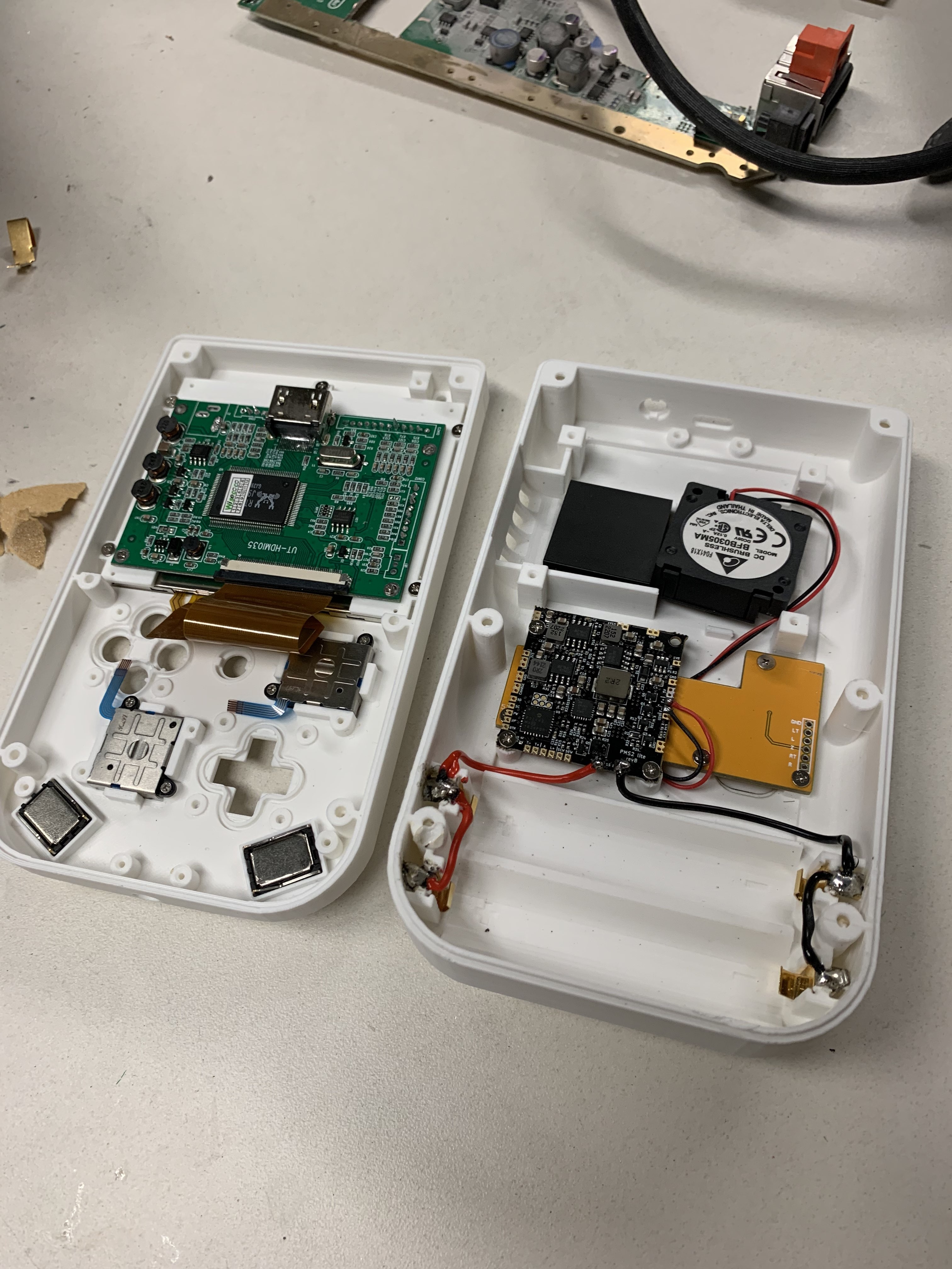
I started with printing the case and the buttons. I used white PLA that I printed on an Ender 3 Neo. The front case printed really well but the back looks like it had some layer shifting at the bottom, leading to the case not closing well.
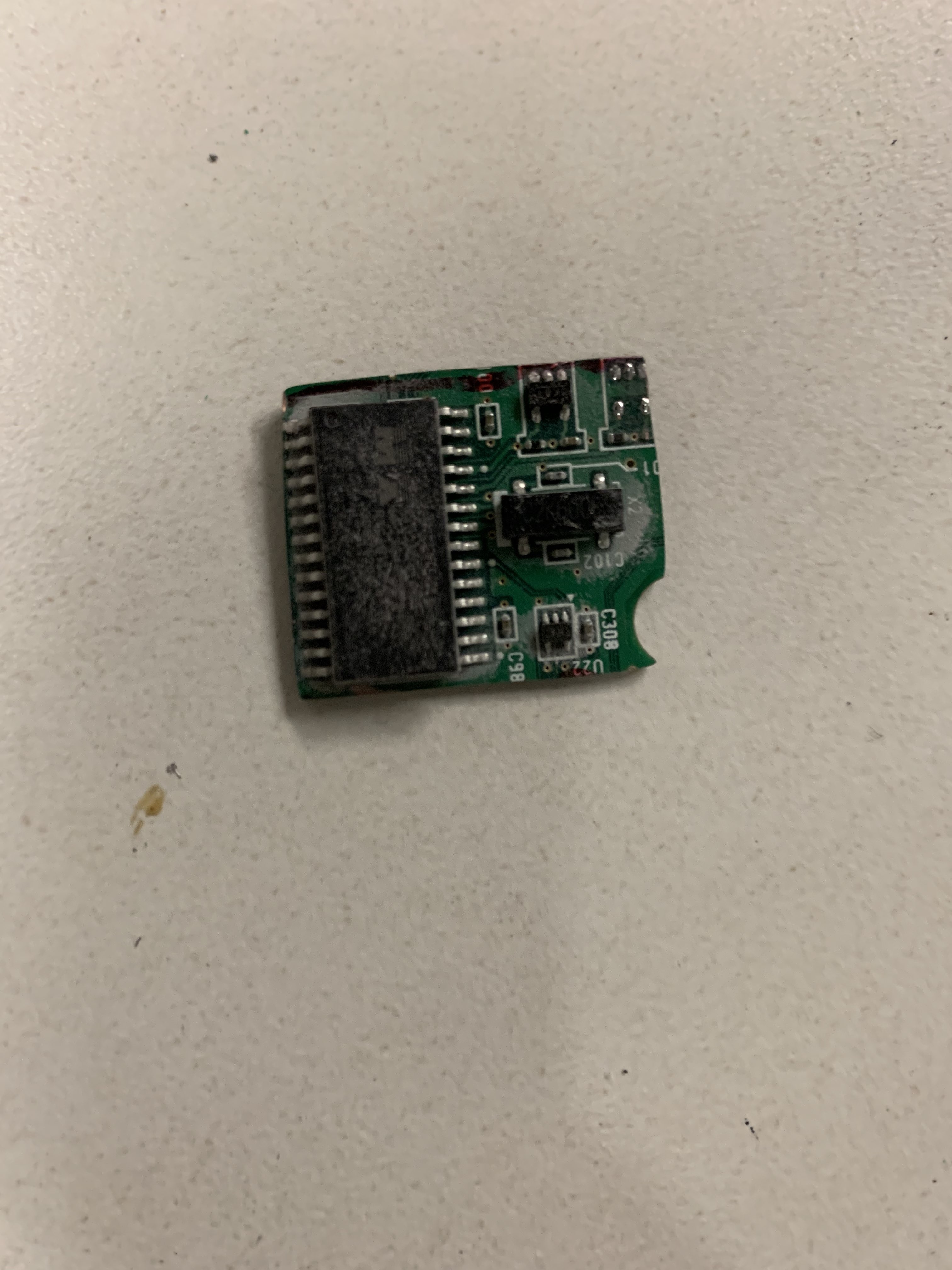
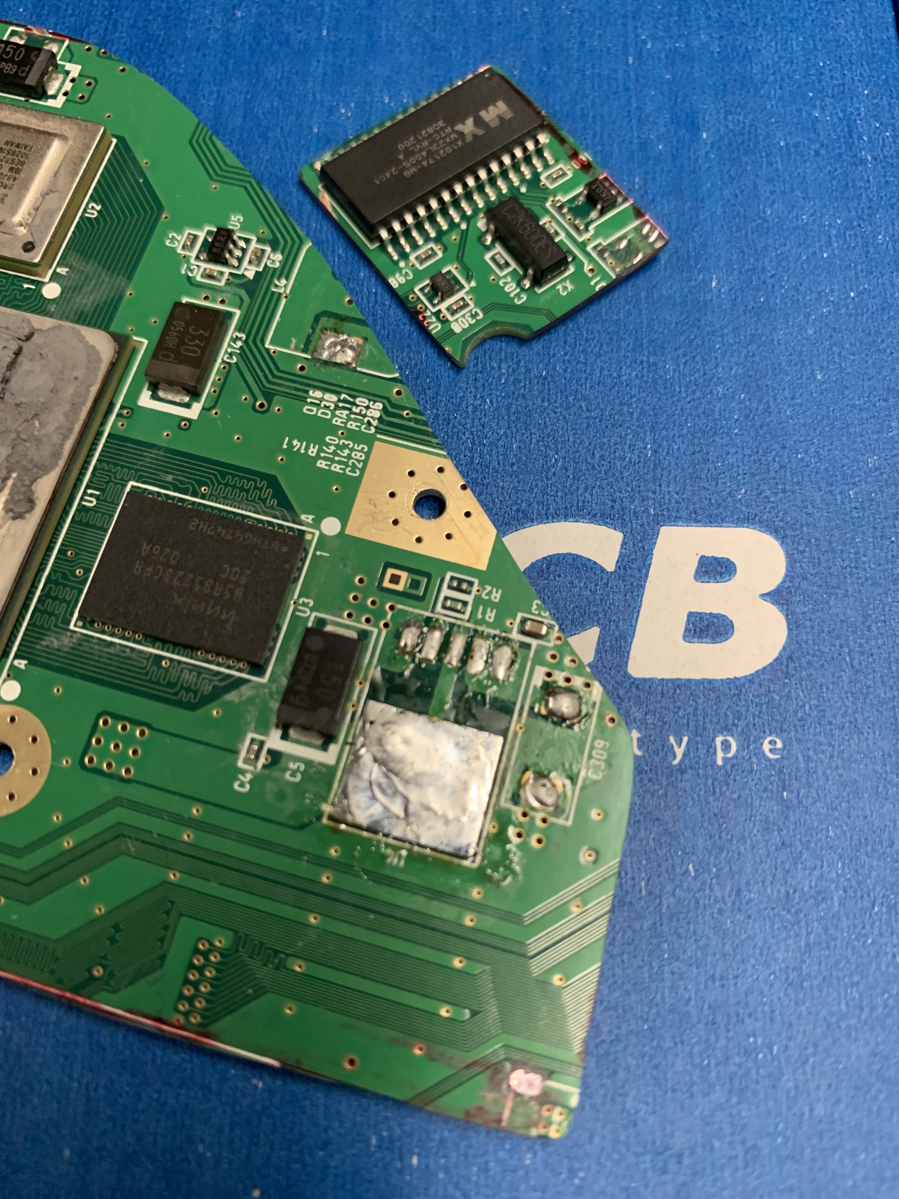
Next, I performed my first Wii trim and tested the resistances, which seemed to come back fine.
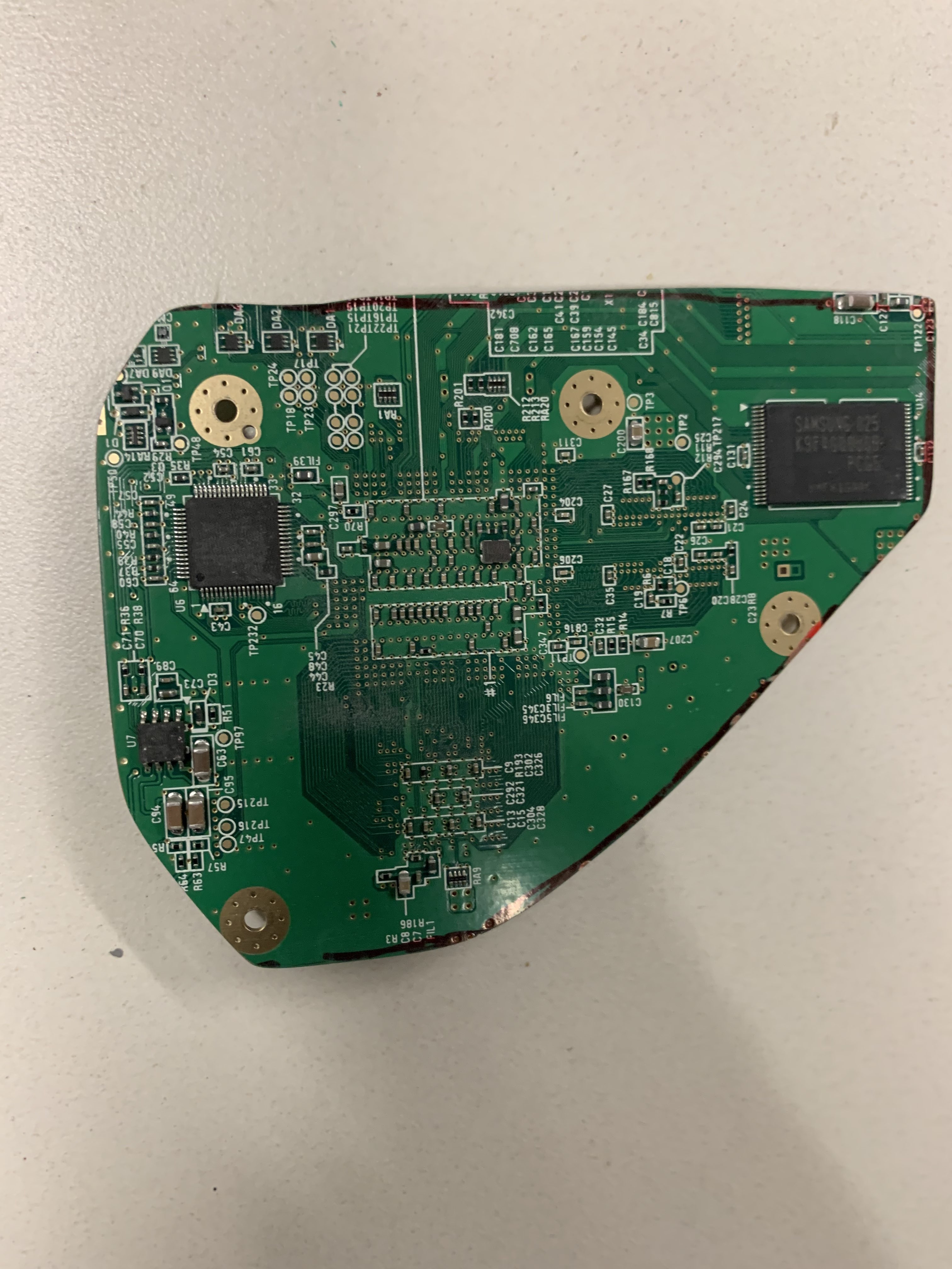
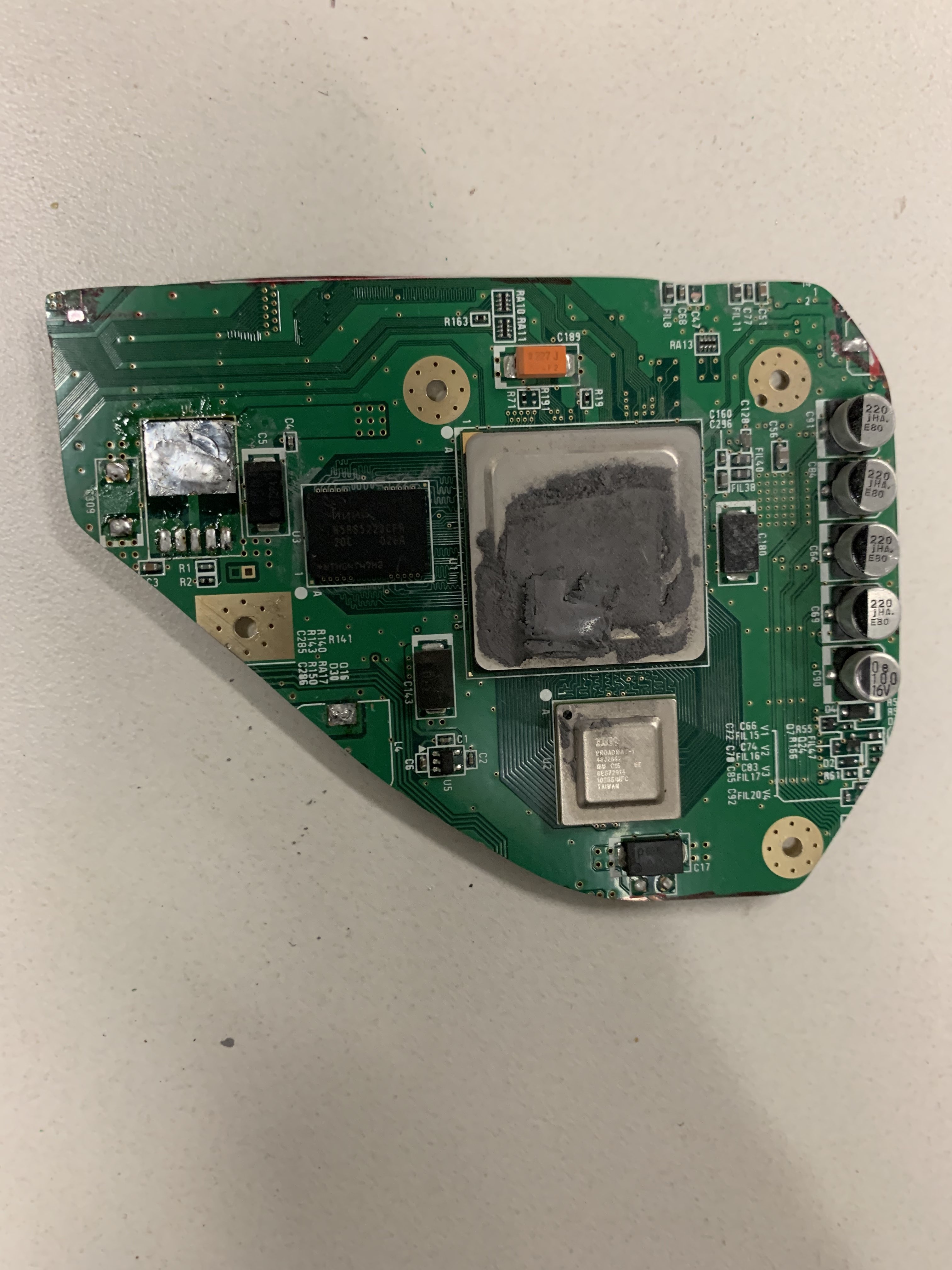
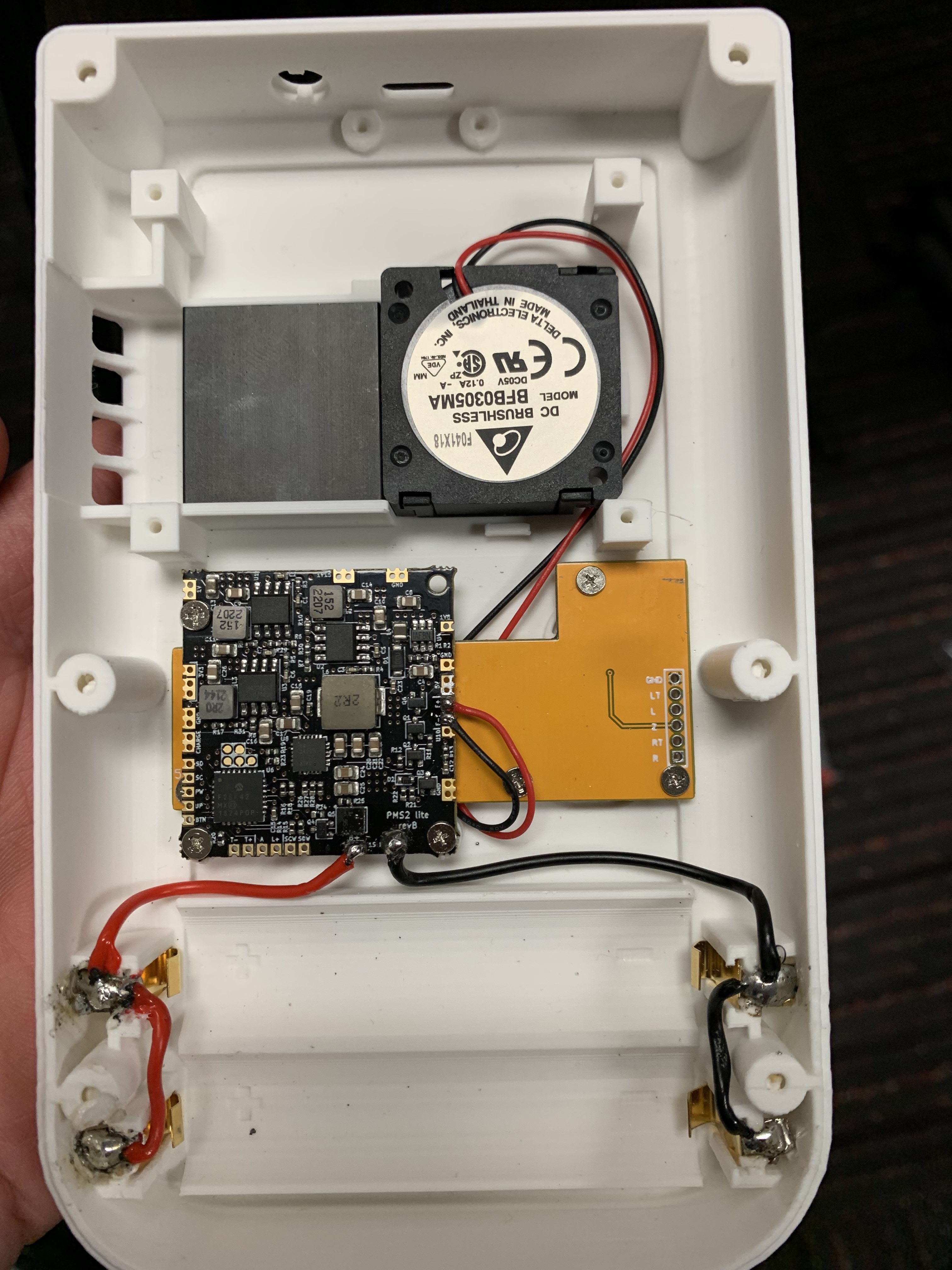
I realized later that because I ordered the PMS-lite, I should've kept the LDO instead of desoldering it, so I will need to find some way to replace that.
I then ran into a few issues:
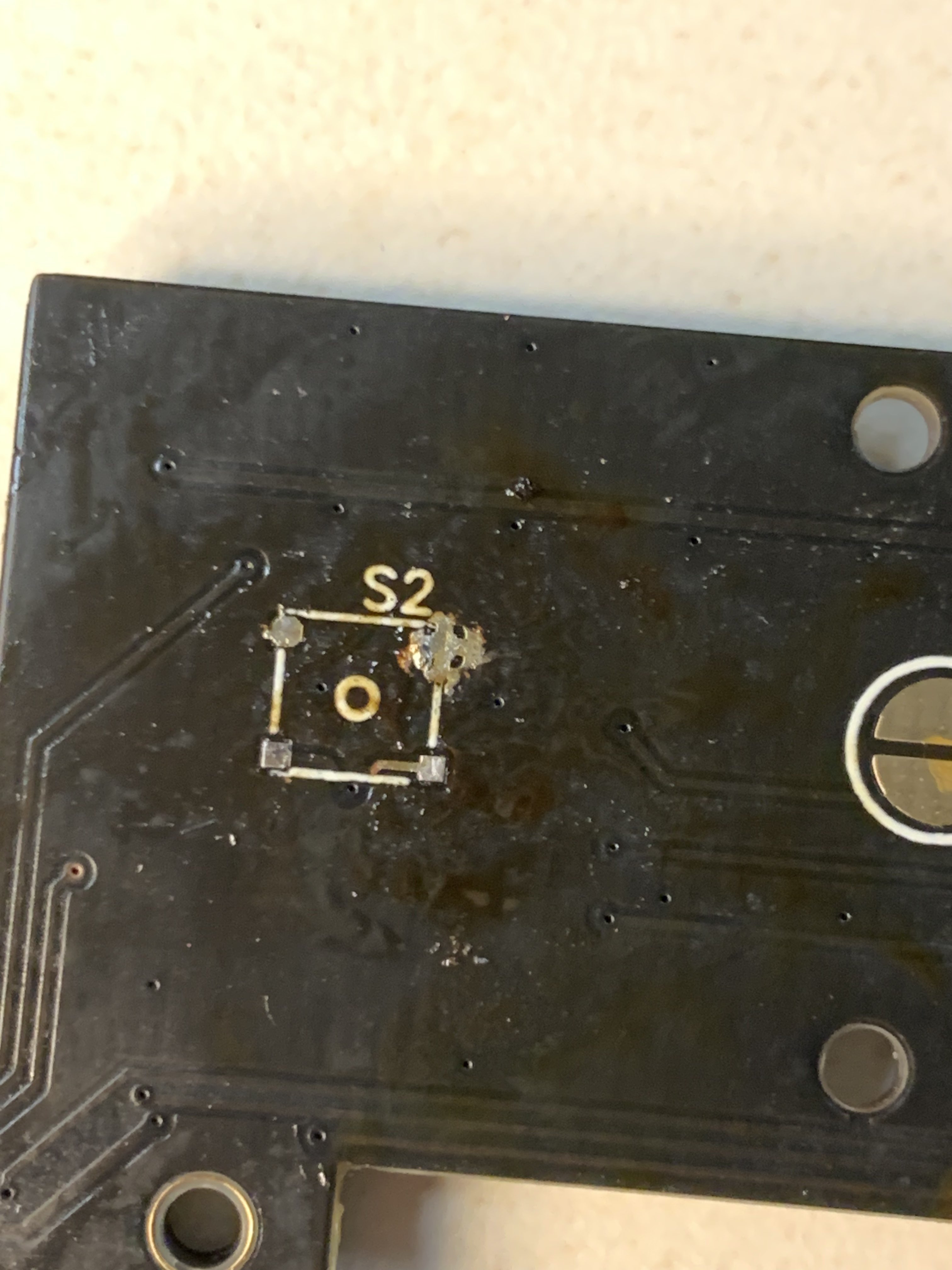
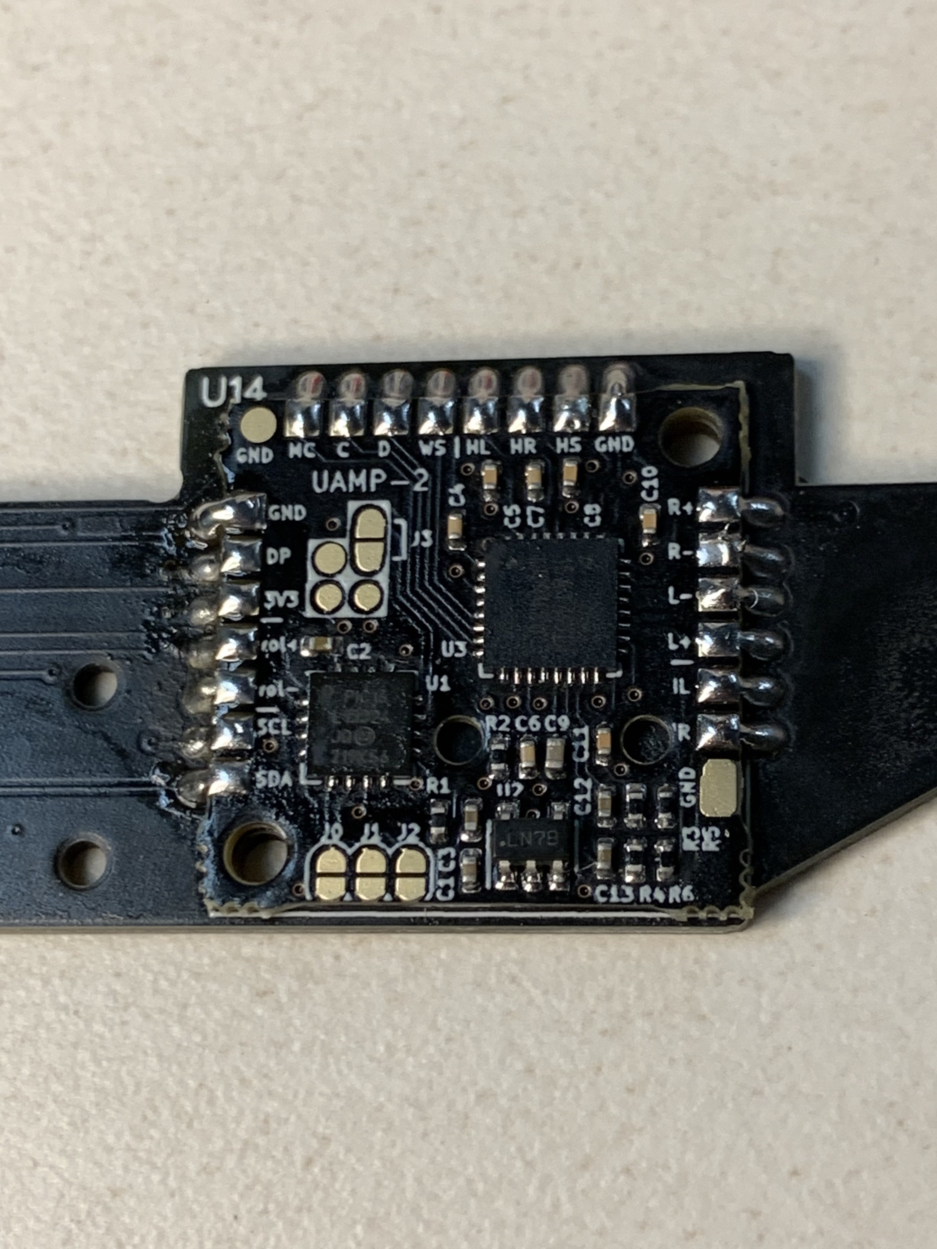
1. While attempting to solder a button, it looks like I might have scratched the surface of the PCB.
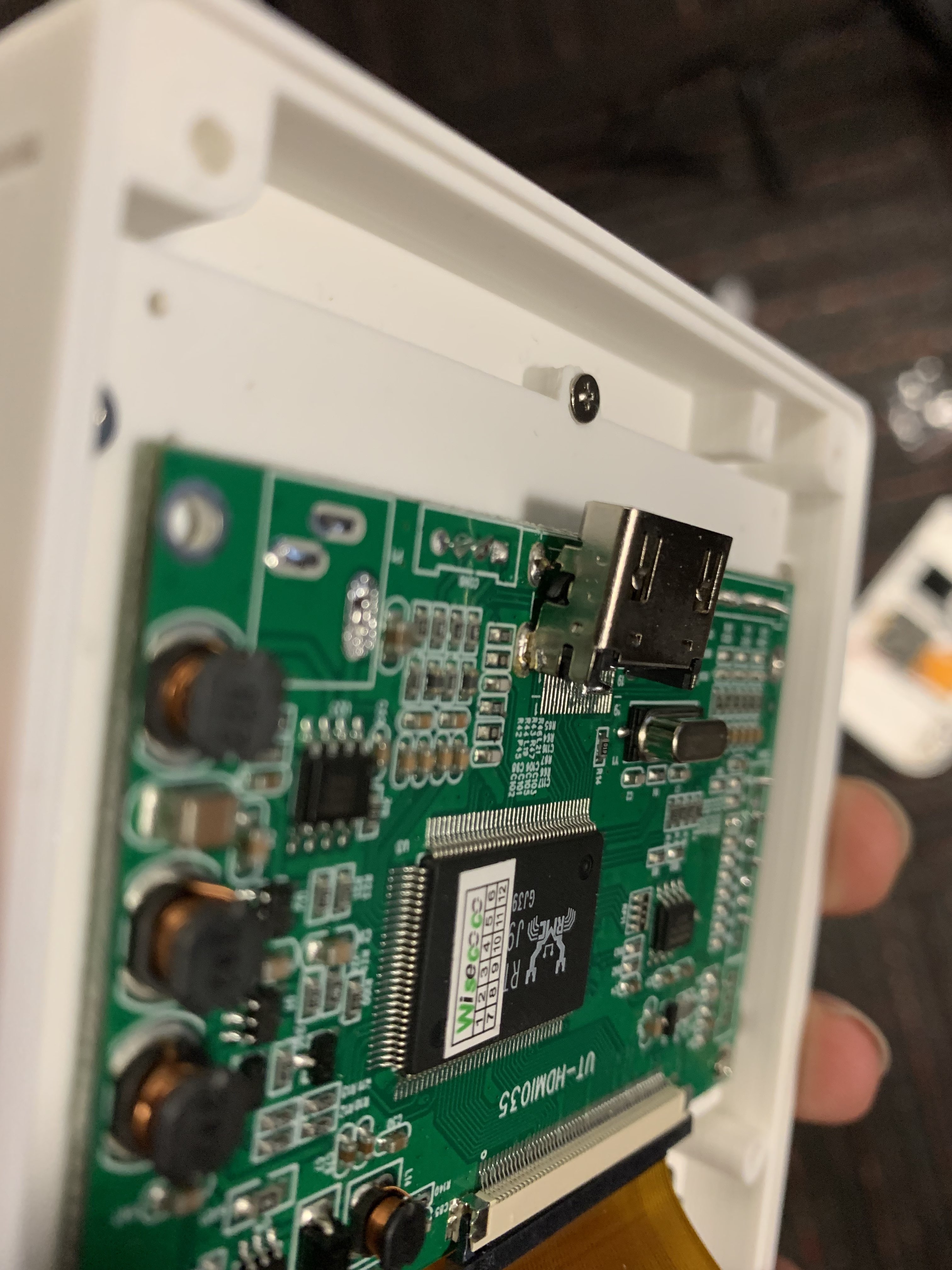
2. I attempted to desolder the HDMI port from the driver board hoping it would come off easily, however, I didn't notice the small pins in the back keeping it in place, resulting in the port being half connected which I'm worried will cause my board to no longer function.
3. As mentioned, I will need to find a replacement 1.8v regulator since I took mine off. Does anyone happen to know where I could find a replacement?
Overall, I thought I made good progress today. Here are some photos of what I have so far, with hopefully more to come")
I recently started my journey of creating a G-boy. When the original Gboy kit came out, I desperately wanted to build one but didn't have the funds to at the time. Now with Gman's STLs, 4LayerTech, and Dustin Fisher's PCBs, I'm hoping to make one of my own!
I started with printing the case and the buttons. I used white PLA that I printed on an Ender 3 Neo. The front case printed really well but the back looks like it had some layer shifting at the bottom, leading to the case not closing well.
Next, I performed my first Wii trim and tested the resistances, which seemed to come back fine.
I realized later that because I ordered the PMS-lite, I should've kept the LDO instead of desoldering it, so I will need to find some way to replace that.
I then ran into a few issues:
1. While attempting to solder a button, it looks like I might have scratched the surface of the PCB.
2. I attempted to desolder the HDMI port from the driver board hoping it would come off easily, however, I didn't notice the small pins in the back keeping it in place, resulting in the port being half connected which I'm worried will cause my board to no longer function.
3. As mentioned, I will need to find a replacement 1.8v regulator since I took mine off. Does anyone happen to know where I could find a replacement?
Overall, I thought I made good progress today. Here are some photos of what I have so far, with hopefully more to come
