
Hi guys,
I thought I'd start a new worklog to share progress updates on the Retro Lite CM5! (however slow they may be!).
I've decided that I want to re-design the Retro Lite PCB from the ground up to support the up and coming RK3588s compute module. With the new release of the Radxa CM5 coming this year, I would like to be able to upgrade my emulation handheld to be able to play GC/PS2 games at full speed, which obviously the Raspberry Pi CM4 cannot do with its poor GPU and lack of CPU cores. At the same time, there were a few flaws with the original design that didn't make a whole lot of sense/left a lot on the table, so I am hoping to at least improve the electronics side of things where I can!
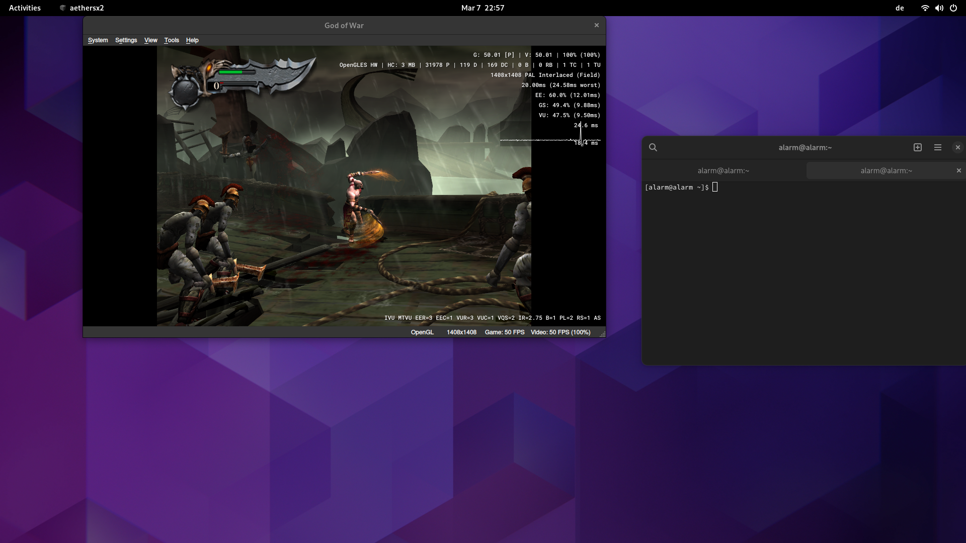
I've ran some tests with the Orange Pi 5 (uses the same RK3588s SOC) and I've been able to get some great performance out of AetherSX2 under Linux with the Open GL ES 3.2 backend and mali blob panfrost drivers. Here it is running God of War at around 7-8W of total power at 2x resolution with minimal dropped frames in Arch Linux. Unfortunately the RK3588s doesn't support Vulkan drivers at the moment but I still think performance is good enough to create a great gaming handheld under Linux.
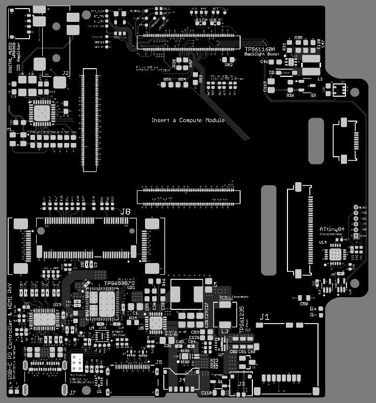
There's a lot of changes that need to be done to the new carrier board to integrate the CM5 module, but I'm hard at work trying to make improvements here and there. Some noteable changes between the CM4 & CM5 include & improved features/goals for the project include:
Touch screen integration would be nice, but I cannot find a symmetrical capactive bezel pre-glued to a 5.5" screen anywhere, so I will most likely not use touch. I don't really like Android anyway for gaming handhelds and EmulationStation doesn't support touch anyway (but it is nice for DS/3DS emulation).


I haven't really made a massive amount of solid progress yet to be honest, but slowly going to chip away at it for fun! But I'll be sure to keep everyone updated when I move forward. Let me know if you have any cool features you can think of!
Thanks for reading!
Check out the GitHub link below for all the details, code and CAD files:

 github.com
I thought I'd start a new worklog to share progress updates on the Retro Lite CM5! (however slow they may be!).
I've decided that I want to re-design the Retro Lite PCB from the ground up to support the up and coming RK3588s compute module. With the new release of the Radxa CM5 coming this year, I would like to be able to upgrade my emulation handheld to be able to play GC/PS2 games at full speed, which obviously the Raspberry Pi CM4 cannot do with its poor GPU and lack of CPU cores. At the same time, there were a few flaws with the original design that didn't make a whole lot of sense/left a lot on the table, so I am hoping to at least improve the electronics side of things where I can!
I've ran some tests with the Orange Pi 5 (uses the same RK3588s SOC) and I've been able to get some great performance out of AetherSX2 under Linux with the Open GL ES 3.2 backend and mali blob panfrost drivers. Here it is running God of War at around 7-8W of total power at 2x resolution with minimal dropped frames in Arch Linux. Unfortunately the RK3588s doesn't support Vulkan drivers at the moment but I still think performance is good enough to create a great gaming handheld under Linux.
There's a lot of changes that need to be done to the new carrier board to integrate the CM5 module, but I'm hard at work trying to make improvements here and there. Some noteable changes between the CM4 & CM5 include & improved features/goals for the project include:
- Third mezzanine connector - this mezzanine breaks out a lot of stuff. I really am only interested in the DP/USB 3.0 lanes
- Stackup - I've changed my PCB to a 6 layer instead of a 4 layer that is signal - ground - power - signal - ground - signal instead of signal - power - gnd - signal. This way I should have more breathing room to route all of the high speed buses and reference planes . I did try on 4 layer but it was quite difficult
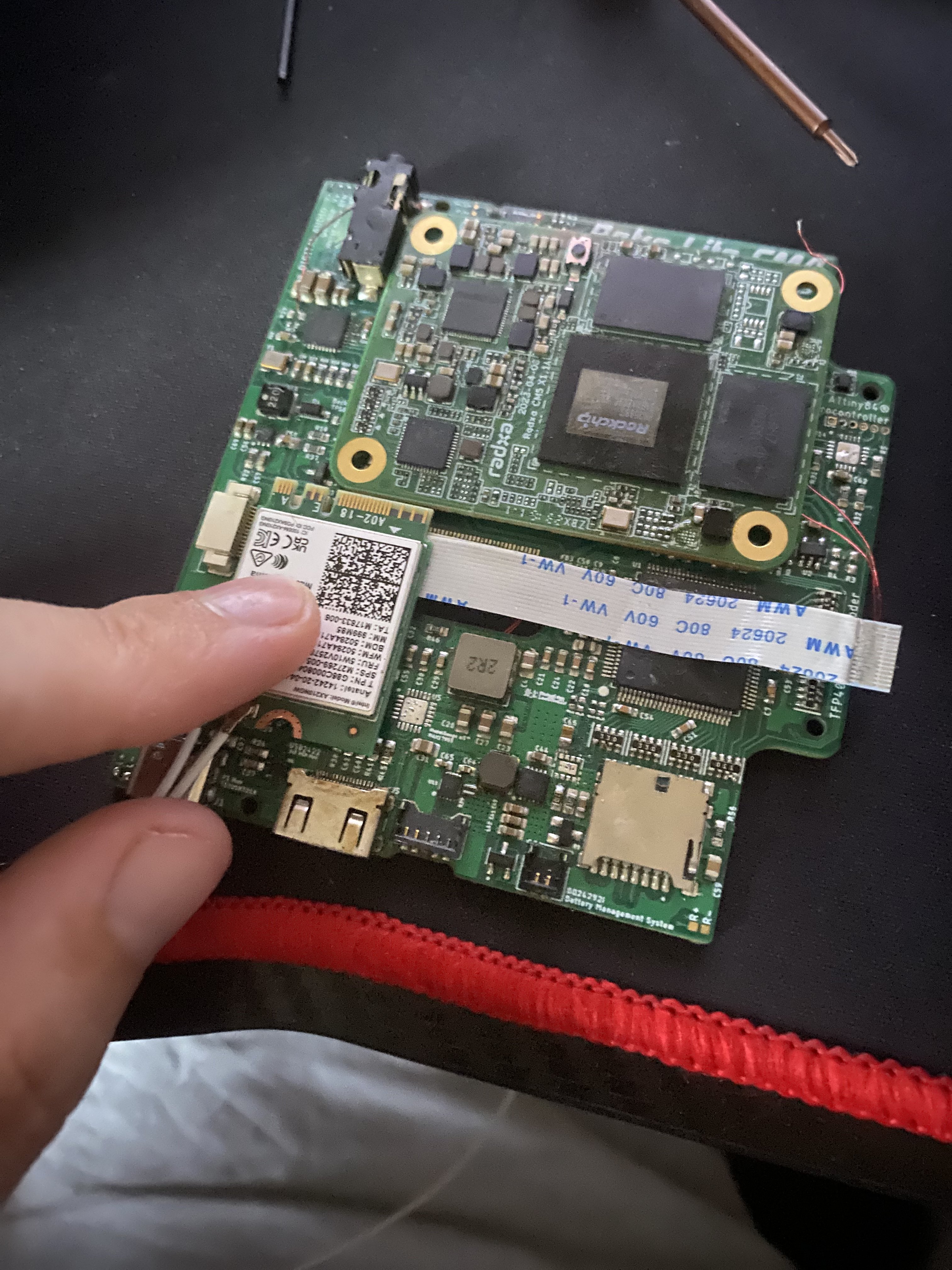
- PCIE 2.0 support - Unfortunately the CM5 does not have WiFi integrated onto the main SBC module, so I've opted to use an AX210 WiFi card which can support BT 5.3 and WiFi 6 from Intel. I've tested this already and it works fantastic with Linux with not much configuration needed. Getting it to fit was a bit of a pain but I think it can just squeeze in next to the fan! I'll need to source some decent antennas too!
- USB 3.0 - available from the SoC itself and will allow for USB 3.0 speeds out of Type-C
- Power - upgrade my 5v regulator to one that can support 15W of power (TPS61235) since the peak power draw of the CM5 is around 12W (3W overhead for other peripherals such as screen backlight, audio & controller)
- Controller - potentially porting the controller code from the ATMEGA32u4 to the RP2040 after my new knowledge gained from the docking project
- Audio - WM8960 i2s audio amplifier with headphone jack support
- DisplayPort - these are available from the SoC itself and now will make for easy video out of Type-C
- DisplayPort/USB 3.0 mux switch - this chip is to switch the DP/USB 3.0 lines where required and also handle the flip/orientation of the USB-C cable in case it is inserted upside down. I'm using the TUSB546 for this in GPIO mode, connected to the USB-PD controller
- Software - I still plan on using RetroPie, however this will be manually installed on top of a CM5 compiled linux kernel and device tree blob for Armbian to support my hardware. We will boot directly into EmulationStation when the console is turned on
as there is likely to be no touch screen supportI lied, there is now a touchscreen! - Frontend - EmulationStation
- HDMI - still plan on keeping the HDMI mini port intact and available, as the RK3588s supports one HDMI TX channel
- Code porting - I need to port over my code from RPi to the CM5. This should be relatively straightforward as I've already found some GPIO libraries that work well, however the hardest part will probably be finding a GPU API like dispmanx that can support writing to the display for battery SoC and other info. I'm not sure exactly how I will solve this issue yet but I'll probably focus on it last
- USB OTG support - 5V out will be supported from the USB-C port to power external peripherals via the TPS65987D, which was lacking in my prior build which was really frustrating. This chip has built in MOSFETs and handles all of the power path switching internally, so its a pretty small footprint solution. It can either be controlled over i2c or can run standalone using a binary program stored on an SPI flash module. This also communicates to the display port mux in GPIO mode or I2C mode to let that muxer know that it needs to flip the signals. It also tells it whether we are in sink, source or DFP/UFP mode
- MIPI 5.5" support (720p resolution display) - integrating a MIPI 5.5" screen to mimic the real Switch Lite dimensions has been a goal of mine for a while (I honestly was a bit disappointed with the poor resolution for streaming games via moonlight) and I think I've figured out how to get it working. Unfortunately reverse engineering the switch lite panel is not something I would even know where to begin with so that isn't an option, but I've found a display that has a linux kernel driver based on the ILI9881C. This would also allow me to use regular switch lite screen protectors so I dont need to paint/buy expensive custom glass sizes
- Replacing the SD card slot with a proper spring loaded connector so it can be removed easily to swap out SD cards
- Keep compatibility with with my Retro Lite CM4 dock
- Gyro support/analog triggers (not sure if I will integrate these to be honest but, nice to haves!)
I haven't really made a massive amount of solid progress yet to be honest, but slowly going to chip away at it for fun! But I'll be sure to keep everyone updated when I move forward. Let me know if you have any cool features you can think of!
Thanks for reading!
Check out the GitHub link below for all the details, code and CAD files:
GitHub - StonedEdge/Retro-Lite-CM5: An upgrade to the Retro Lite CM4 handheld, which uses the RK3588s compute module from Radxa.
An upgrade to the Retro Lite CM4 handheld, which uses the RK3588s compute module from Radxa. - GitHub - StonedEdge/Retro-Lite-CM5: An upgrade to the Retro Lite CM4 handheld, which uses the RK3588s...
github.com
Last edited:
") I also plan to replace the FFC connectors with ZIF style flip lock connectors instead of the sliding lock ones which I find in general are just more fiddly.
I also plan to replace the FFC connectors with ZIF style flip lock connectors instead of the sliding lock ones which I find in general are just more fiddly.