
Xyzven
.
- Joined
- Jul 29, 2023
- Messages
- 39
- Likes
- 12
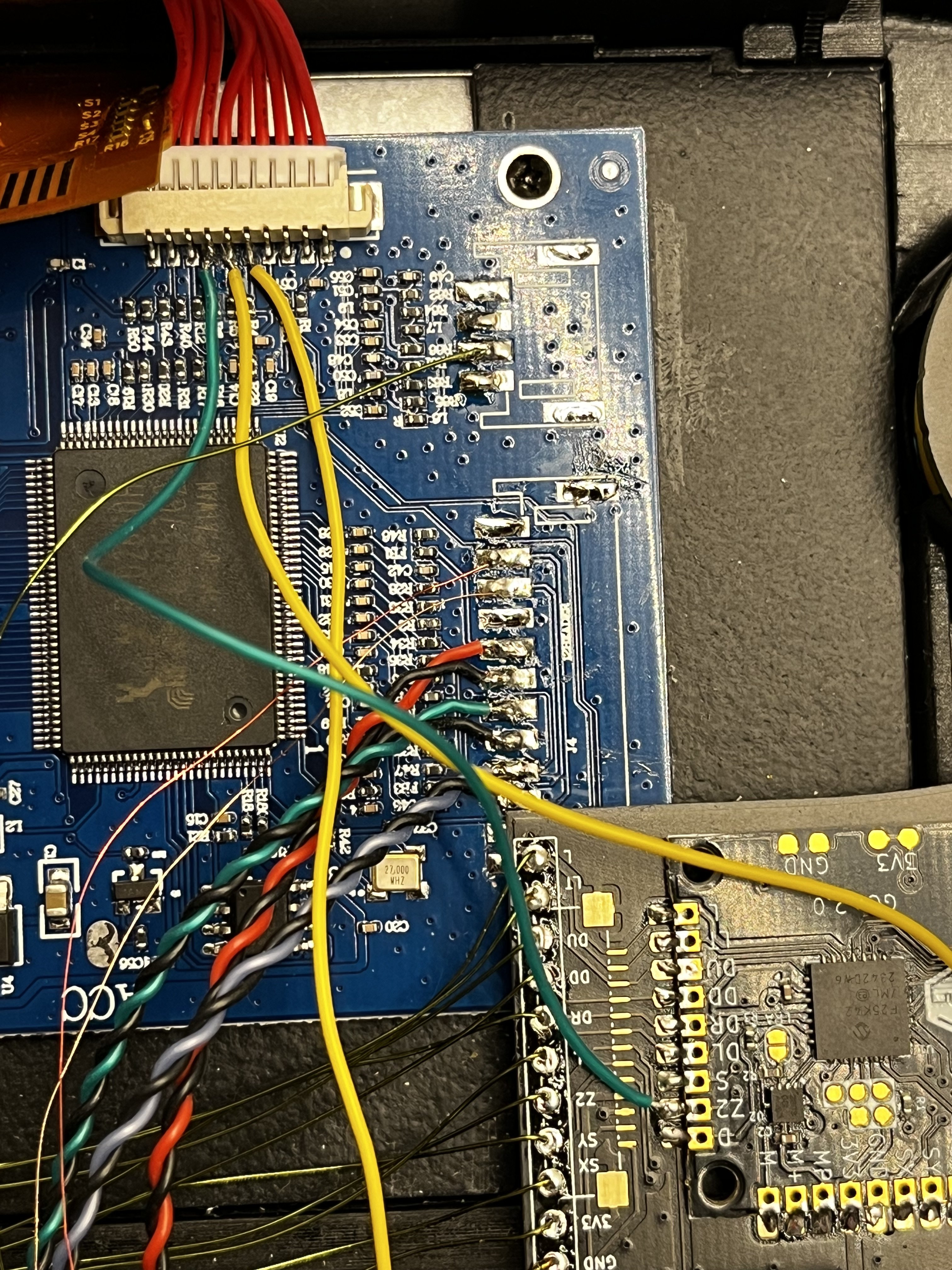
So I have tested my wii build with the composite output and I get a good boot. All my items are detected as expected. RVloader 2.0 works well and I have no complaints.
ISSUE: Screen/driver board does not detect VGA output.
CHECKS:
- SHORT between R/G/B and ground: Resistance between R/G/B and ground is 75 ohms from the wii board, and with the screen driver board attached, it drops to 37 ohms. So I consider not shorted.
- Bad driver board: I have used two different driver boards to test.
- Select screen input: I have used the "driver selector" daughter board but it refuses to move to VGA and just turns off the screen.
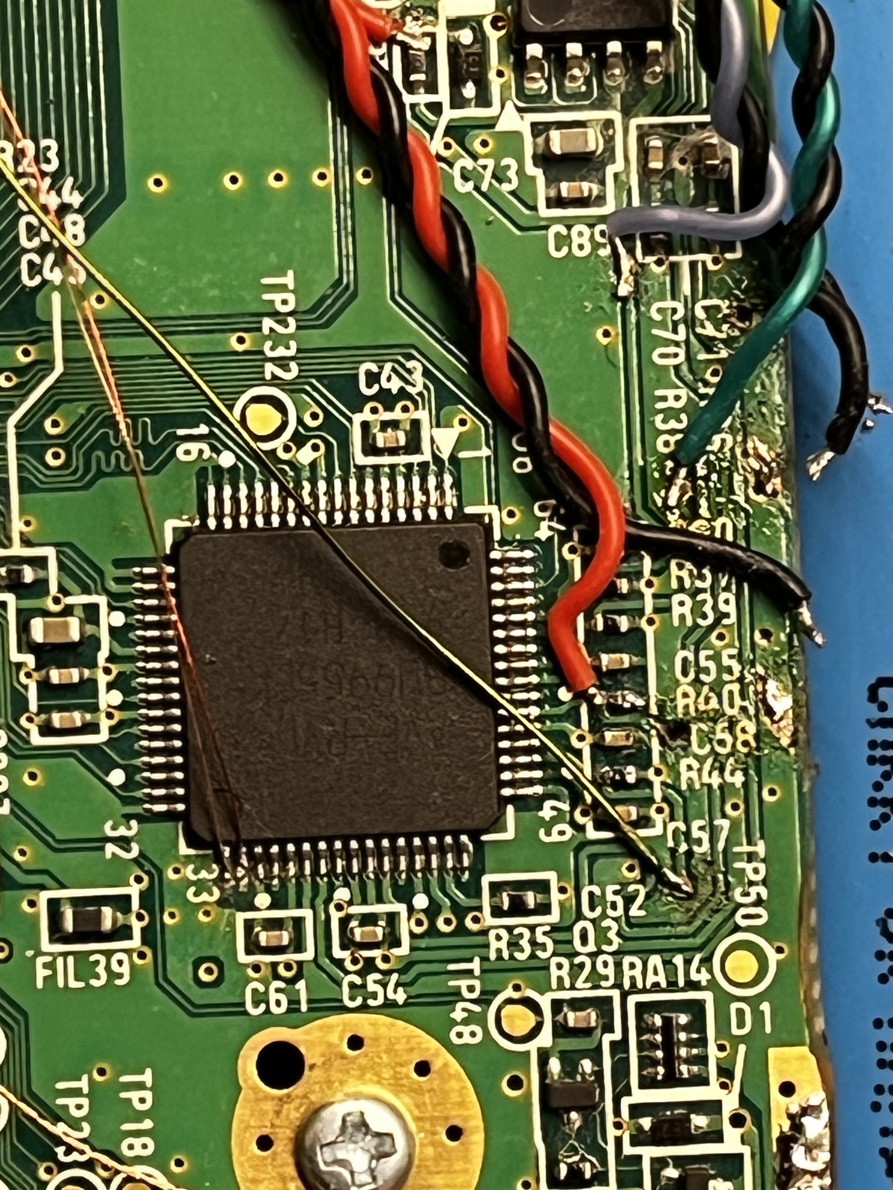
- Mode does not have 3.3v: double checked TP47 has 3.3v on it (you can see where I draw power from in the very top of the image)
- RVLoader doesn't have VGA patched: Re-ran the installer in Safe boot and verified it was patched.
- Wires are bad: changed out wiring three times (so much so that I pulled the RED trace post cap)
- H/V sync are shorted or bridged: verified with meter that this is not the case and they go correctly to the board. (even tried swapping them in case the board is mislabelled)
- Is R/G/B outputting? I used a meter to check for voltage and I get voltage across them when TP47 is connected (although it's very little).
I'm lost as to where to go from there as everything else worked perfectly when using composite. I just dislike the resolution in composite and want to get VGA working. Any help would be appreciated.
ISSUE: Screen/driver board does not detect VGA output.
CHECKS:
- SHORT between R/G/B and ground: Resistance between R/G/B and ground is 75 ohms from the wii board, and with the screen driver board attached, it drops to 37 ohms. So I consider not shorted.
- Bad driver board: I have used two different driver boards to test.
- Select screen input: I have used the "driver selector" daughter board but it refuses to move to VGA and just turns off the screen.
- Mode does not have 3.3v: double checked TP47 has 3.3v on it (you can see where I draw power from in the very top of the image)
- RVLoader doesn't have VGA patched: Re-ran the installer in Safe boot and verified it was patched.
- Wires are bad: changed out wiring three times (so much so that I pulled the RED trace post cap)
- H/V sync are shorted or bridged: verified with meter that this is not the case and they go correctly to the board. (even tried swapping them in case the board is mislabelled)
- Is R/G/B outputting? I used a meter to check for voltage and I get voltage across them when TP47 is connected (although it's very little).
I'm lost as to where to go from there as everything else worked perfectly when using composite. I just dislike the resolution in composite and want to get VGA working. Any help would be appreciated.
