
Jpin
.
- Joined
- Sep 17, 2021
- Messages
- 39
- Likes
- 24
Hi guys, after several attempts without success that includes 3 PMS lite and 3 Wii’s fried and taking a long break from portables I tought live is not just portables, lest distract from portables playing some AOE2 doing some 3dprints but at the end of the day I was still thinking about PORTABLES... how to make it work and what else to read to make it happen and the most important if it was worth it. So…. I found that im not going to be in peace until I finish this project that I have started a year ago most likely.
So here I am back on track and with a bit of hope that I can make it, let’s do this……
I just find out that 4Layers is short of everything, so I have to do this portable with customs regulators and try to use the PMS-PD, Uamp and GC+2 that I have from previous attempts.
Here is me progress so far.
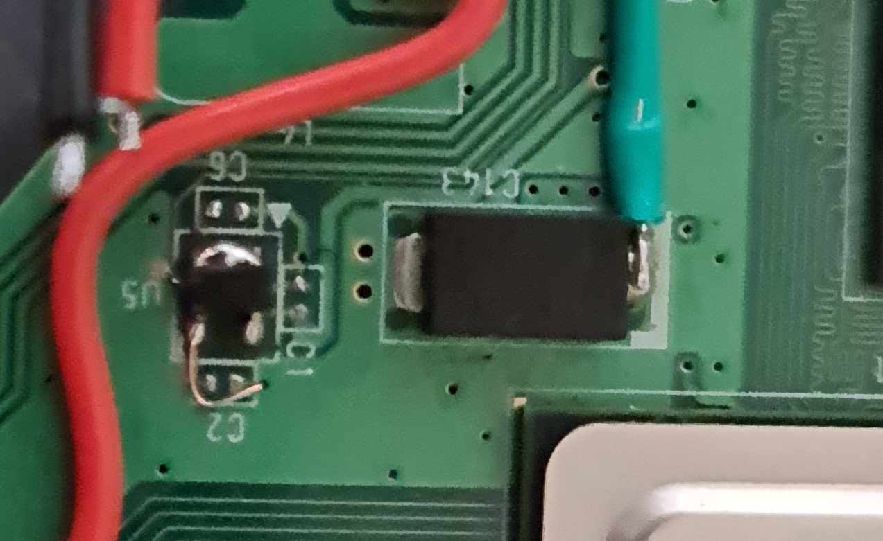
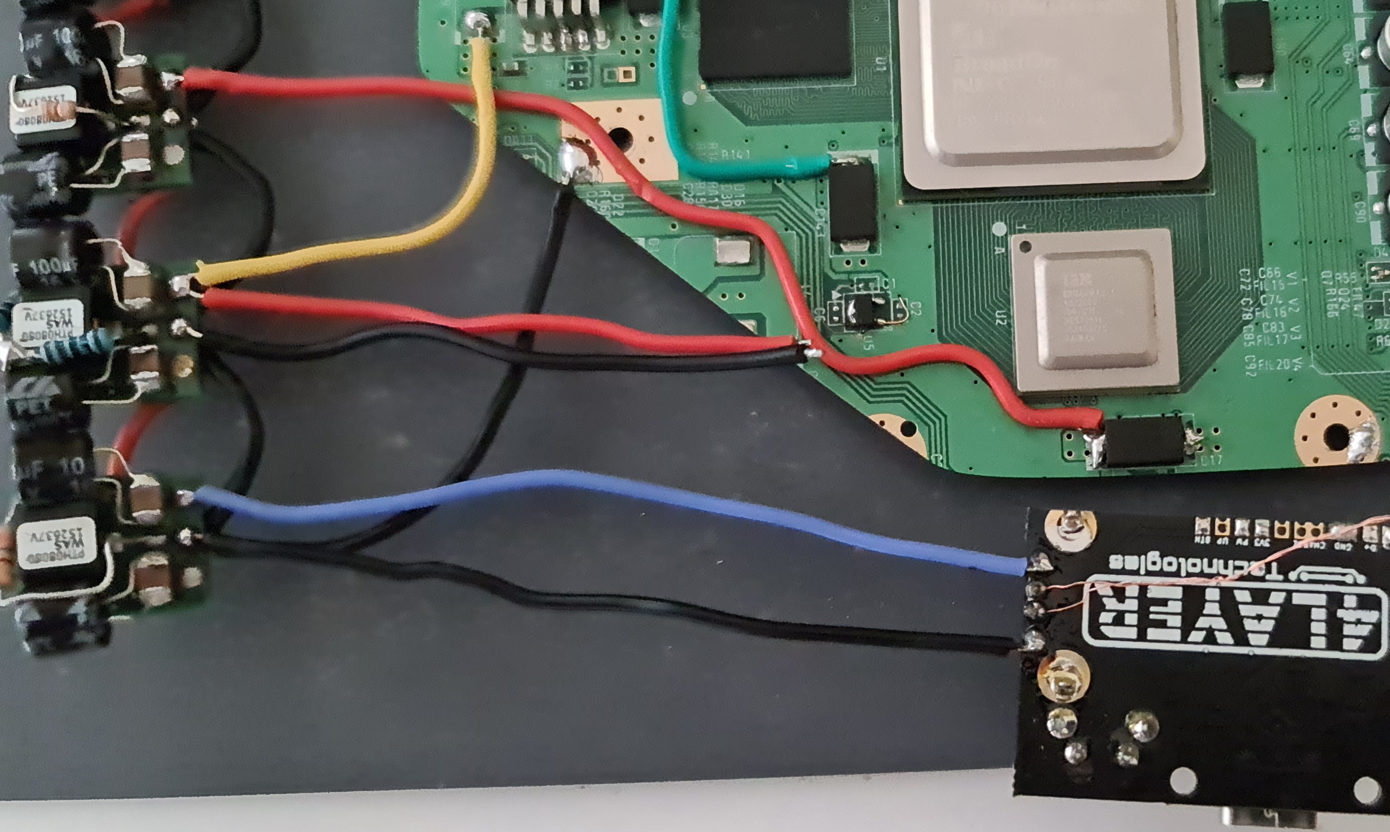
First of all U10 relocation and then customs regulators
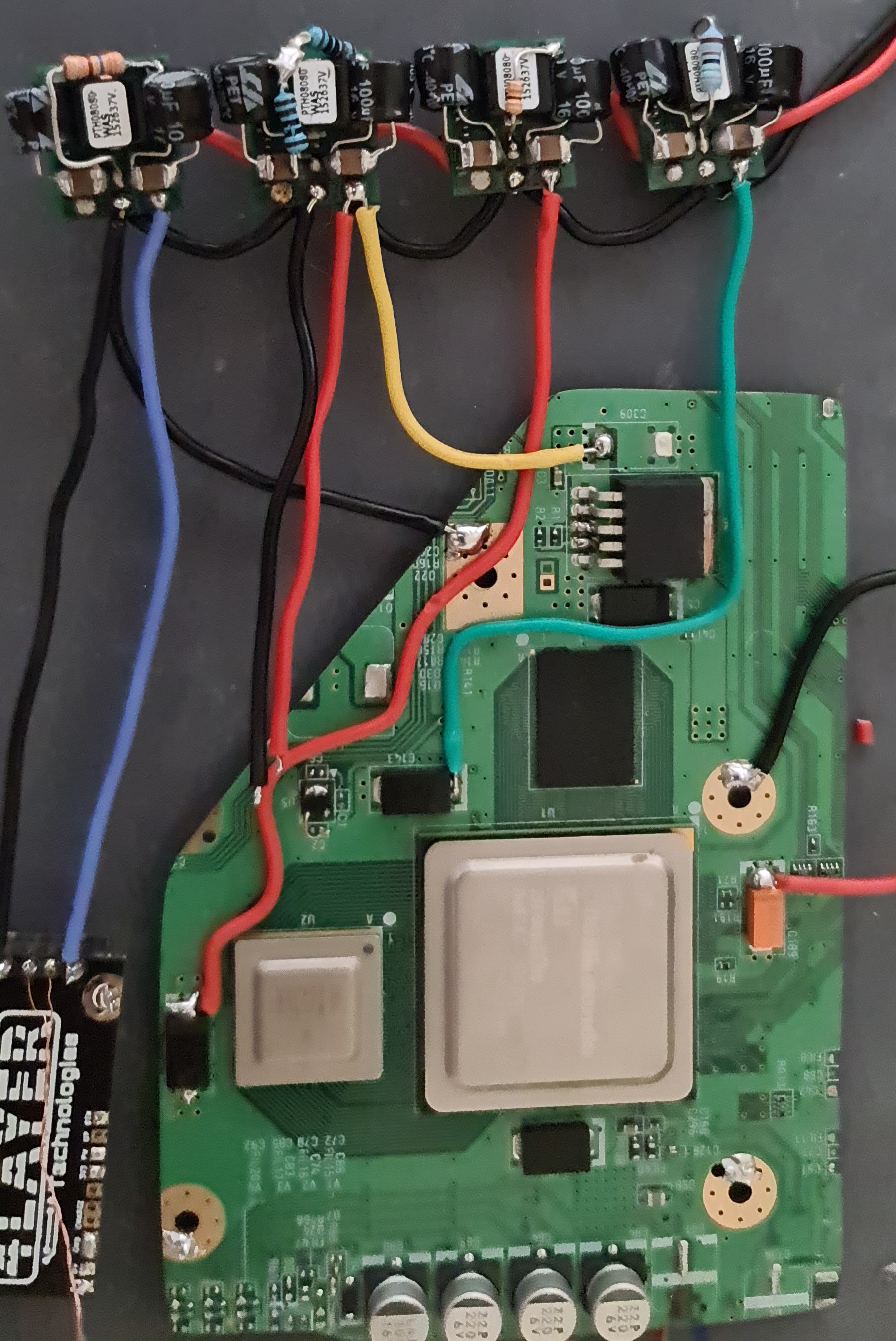
I used the PTH08080 with 2 100uf capacitors on each regulator and here is the table of resistors.
1v = 75k
1.15v = 30k
3.3v = 2k
5v = 360
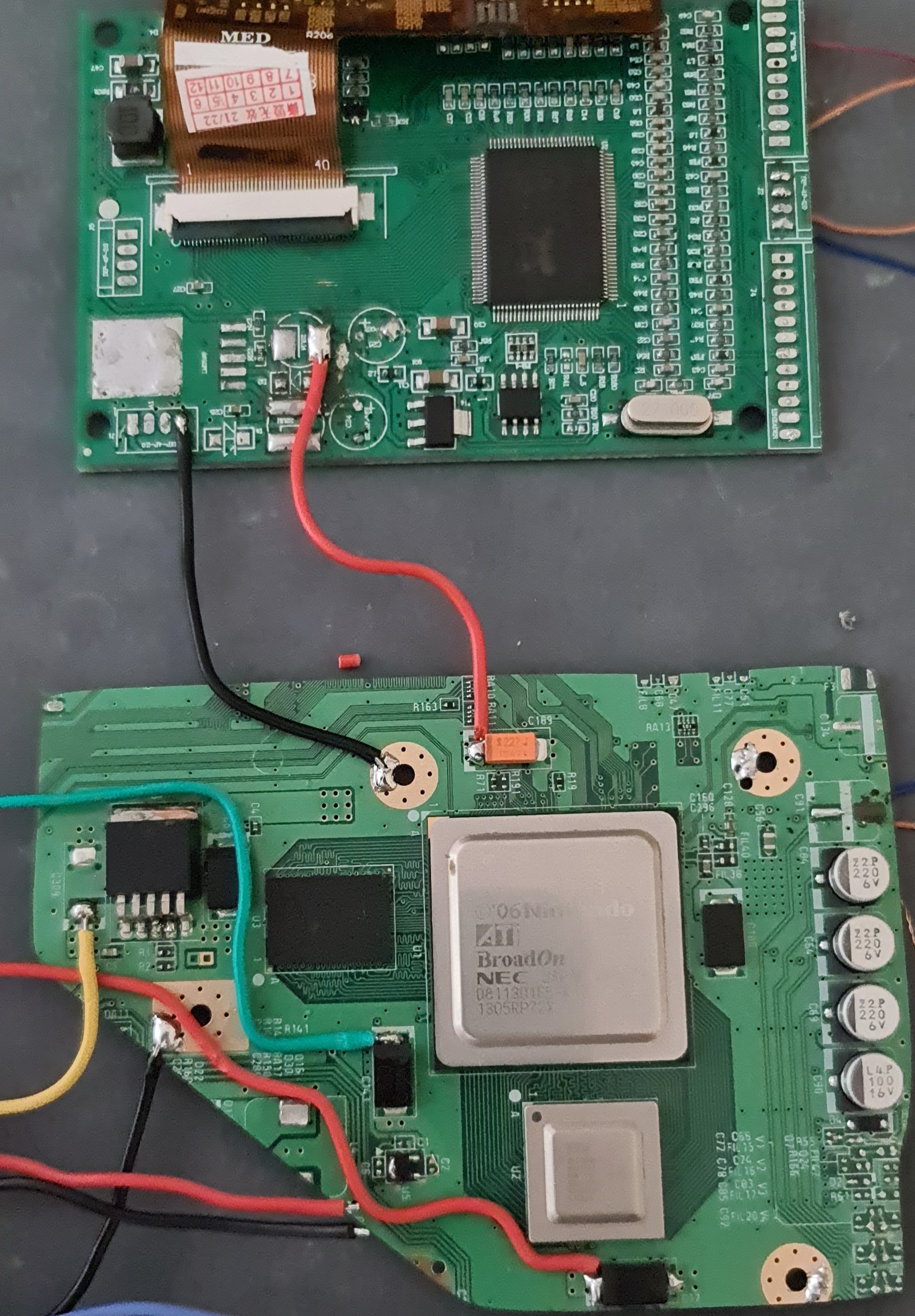
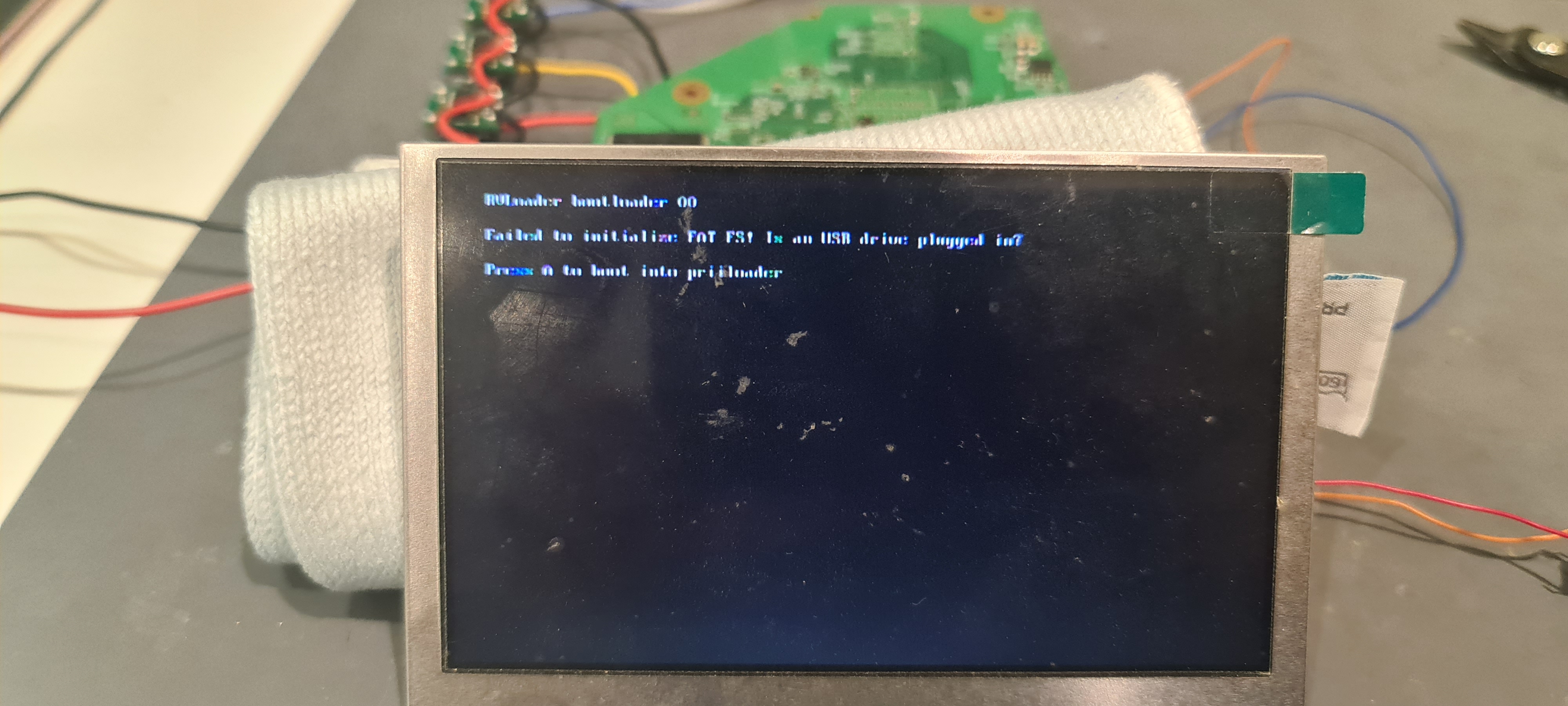
After checking the right voltage from each regulator I did the first composite test using the tv wich I find more practical in order to have a few wires connected to the board and figure out any problem if find any, fortunately was smooth and work.
I don’t know much about how to use the regulators in terms of wire couse i was more focus on the PMS lite before but with a bit of @Gmans help I did wired the screen to the WII board and did the test with it wich ended up just fine.
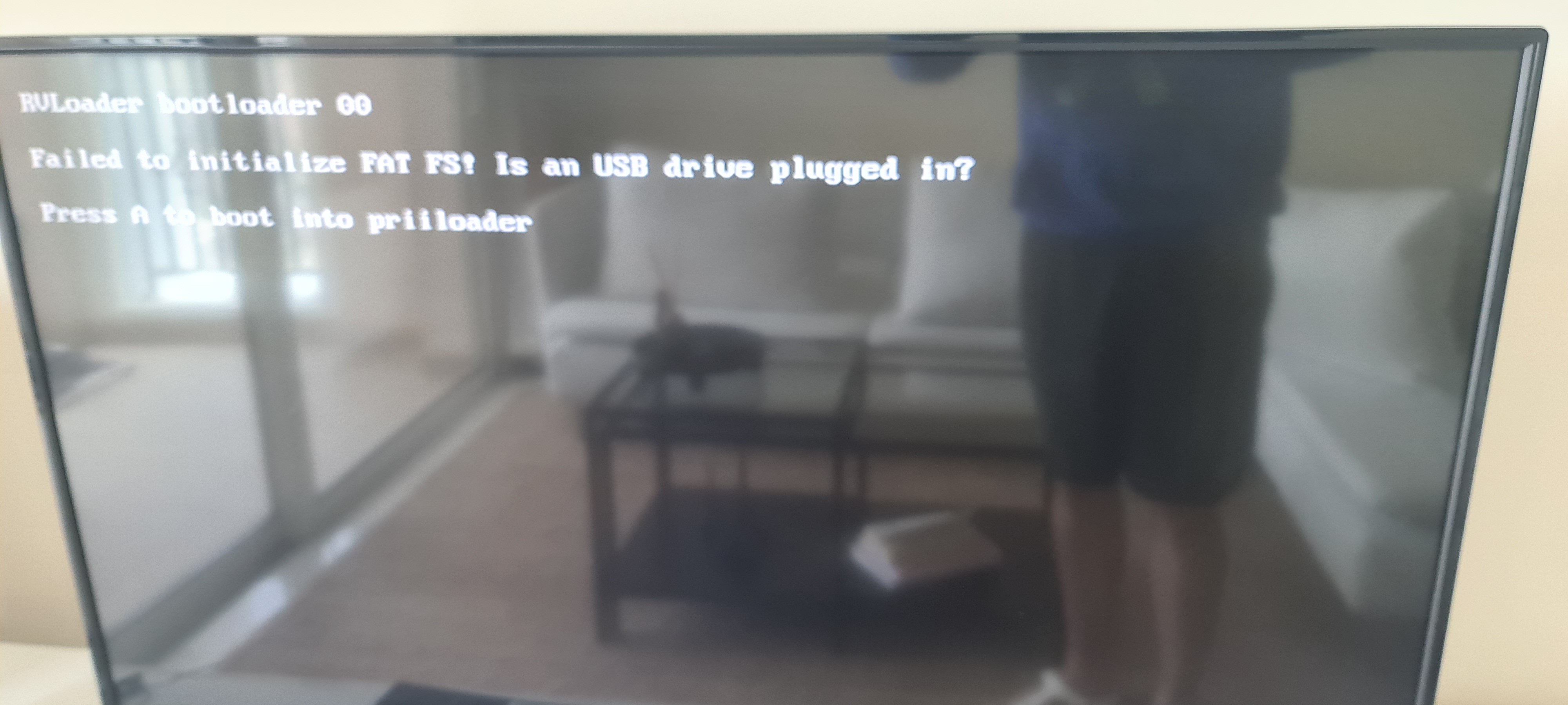
Time to test the USB using the 4Layers PD and that will be my work for this week, for sure must be one of my best weeks cause everything is going smooth.
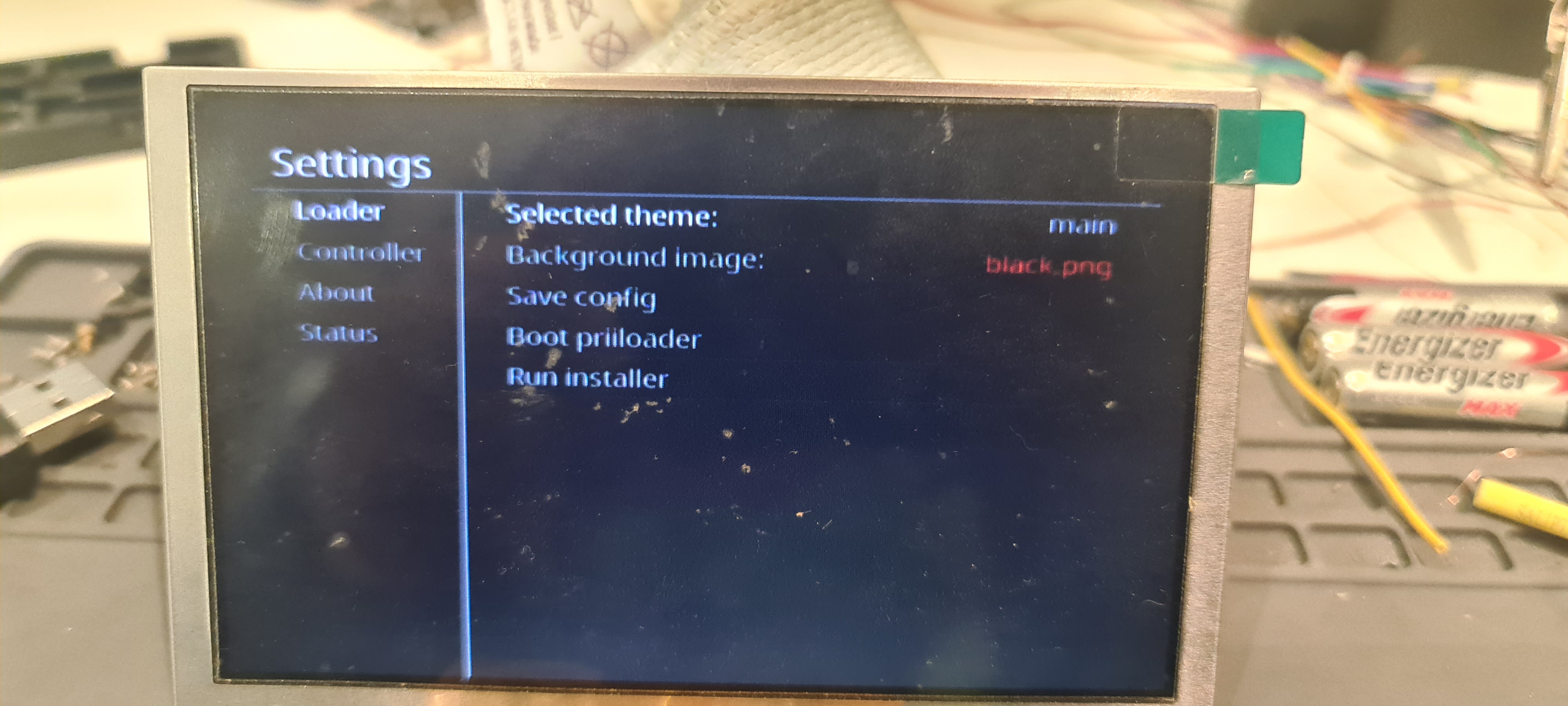
Its working can’t believe it, next step have to clarify some doubts and continue.
I have connected the 5v, D-, D+ and GND direct to the USB at the back of the PCB to make it worked. So, I don’t know if connecting the 3v to the PD will allow me to use the on, off button (I don’t think so), charger the batteries with the USB-C port that it has, or I have to do the same as I did with the USB wire them separately? And is there any risk wiring 5v and 3v at the same time on the same PCB this case PMS PD?
Can I take the Uamp and GC+2 3v from the wii or it has to be from the 3v regulator?
Thanks for reading and help
So here I am back on track and with a bit of hope that I can make it, let’s do this……
I just find out that 4Layers is short of everything, so I have to do this portable with customs regulators and try to use the PMS-PD, Uamp and GC+2 that I have from previous attempts.
Here is me progress so far.
First of all U10 relocation and then customs regulators
I used the PTH08080 with 2 100uf capacitors on each regulator and here is the table of resistors.
1v = 75k
1.15v = 30k
3.3v = 2k
5v = 360
After checking the right voltage from each regulator I did the first composite test using the tv wich I find more practical in order to have a few wires connected to the board and figure out any problem if find any, fortunately was smooth and work.
I don’t know much about how to use the regulators in terms of wire couse i was more focus on the PMS lite before but with a bit of @Gmans help I did wired the screen to the WII board and did the test with it wich ended up just fine.
Time to test the USB using the 4Layers PD and that will be my work for this week, for sure must be one of my best weeks cause everything is going smooth.
Its working can’t believe it, next step have to clarify some doubts and continue.
I have connected the 5v, D-, D+ and GND direct to the USB at the back of the PCB to make it worked. So, I don’t know if connecting the 3v to the PD will allow me to use the on, off button (I don’t think so), charger the batteries with the USB-C port that it has, or I have to do the same as I did with the USB wire them separately? And is there any risk wiring 5v and 3v at the same time on the same PCB this case PMS PD?
Can I take the Uamp and GC+2 3v from the wii or it has to be from the 3v regulator?
Thanks for reading and help