
- Joined
- Dec 16, 2016
- Messages
- 1,122
- Likes
- 2,710
- Location
- The Oregon Wildlands
- Portables
- just so many i am so cool
I guess it's time.
I stopped building Wiiboy Colors because I did not enjoy assembling the USB-C and old PMS boards needed to build them. Unfortunately, there just isn't enough space in the case to fit a PMS-2 and a PMS-PD inside, so I never bothered to do a redesign to use modern boards.
BUT with the aggressive LMAO trim, I can shift the Wii and cooling setup up ~6mm. This opens up just enough space for the PMS-2 to squeeze in between the cooling setup and the batteries. The PD board won't fit, but this change means that there's now enough space for the other 4LT boards.
My goal with this redesign is to integrate everything as cleanly as possible. Here's a breakdown of the 5 custom circuit boards that the redesign uses.
The Front Board
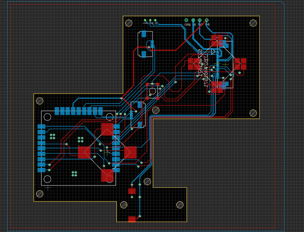
Very similar to the front board in the original WBC. Still uses DS Lite membranes/buttons and connectors for Switch joysticks, but it now has a footprint for the 4LT GC+ 2 to solder into. The design still features the FFC cable that goes between the two halves, although the video signals no longer run through it. While the FFC cable only looked super clean, I got pretty noticable screen interference when I ran everything over the cable. Screen wires will need to be run across the two halves manually, but I think that's for the best. Still only one speaker. There is space for two speakers to flank the dpad/c-stick, but I hate how that looks. I like the look of my one speaker setup, so that's how it's gonna stay for now.
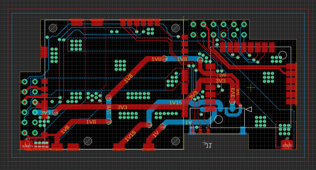
The Main Back Board
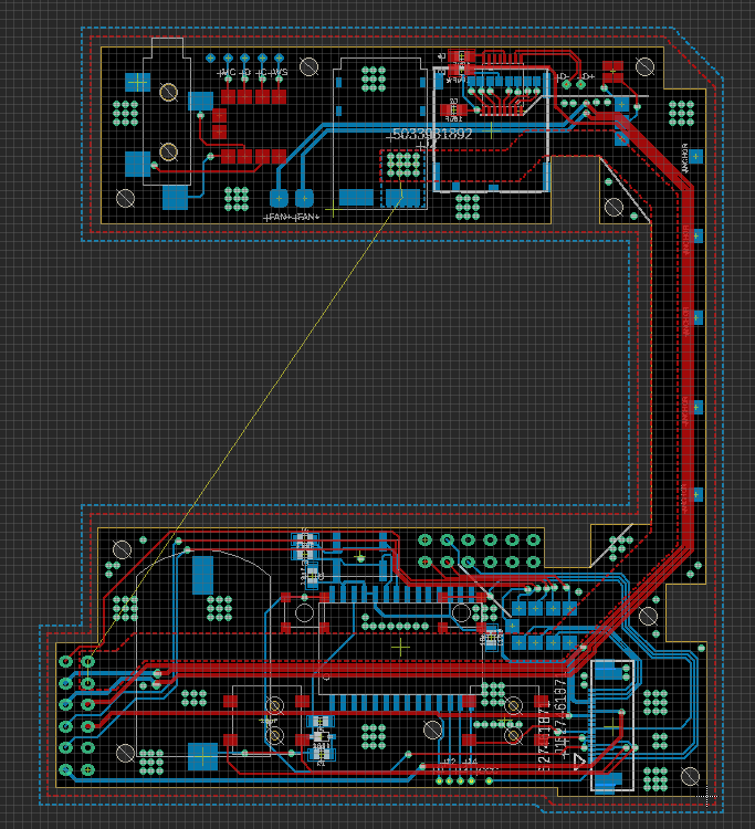
The original WBC used two different boards for the top and bottom, but I've merged them into one board. The top half still houses the headphone jack, LED, and PD charging board. For now, I'm using the same $2 PD board that I used in my WiiVision. It's not really meant to be modular, but I'll try just soldering it directly to this board. Not the most elegant solution, but it'll allow for either 9v or 12v PD charging, which is all I really need. I've also implemented the GL823K microSD-USB chip for USB on the Wii. I've been using this chip on some of my Louiis for the past year, and it's the same chip that 4LT uses on the PD3. Really cool chip, and I've never run into any compatability issues with RVLoader, which is what I care about the most.
The bottom of the board still houses the triggers and MX chip circuitry. There's now a proper battery holder, which fits a 2016 coin cell battery. The bottom half also has pads/vias for three other circuit boards to latch onto.
Audio Board
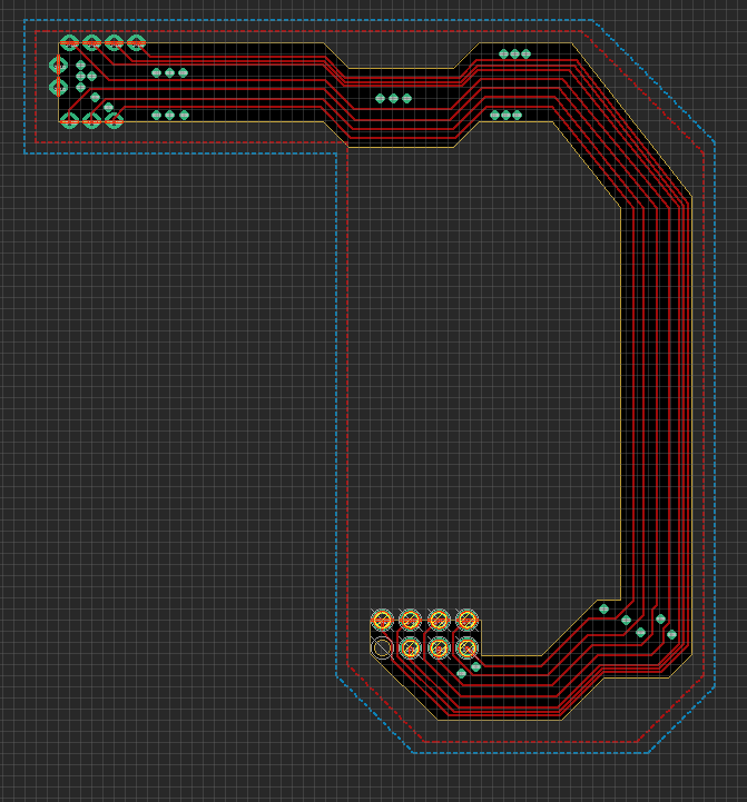
The idea with this board was to have the headphone and digital audio signals running seperately from the power signals on the other board, with a solid ground plane between them to hopefully help mitgate interference on those lines. Uncertain whether this will help much, but we'll at least give it a shot. If interference is still bad, then there's still room to fit the open-source U-Amp circuit in the top board, but I'd like to avoid fine SMD assembly for these boards if I can.
Button Board
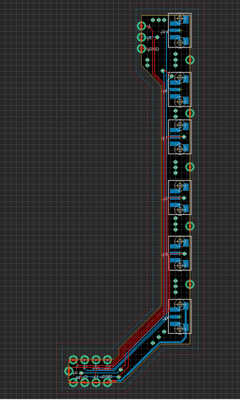
This board also uses castellated edges and runs along the other side of the board. Houses the tacts for power, volume control, and screen menus. I'm not in love with having this many buttons crammed into the side of the portable, so I'm considering implementing CrazyGadget's screen controls through GCC board to get rid of a few buttons.
PMS/ U-Amp Housing Board
You'll never guess what's on this board...
This board currently solders directly to the main bottom board, to bring all the audio and power signals to the bottom. I'd like to find some sort of connector to allow the two boards to come together and apart in a much nicer way. I'm currently using 0.1" header pins to mount them together, and the thinnest header pins connectors of this size still add up to over 7mm. I need something that can fit in the 2.6mm - 4.5mmish range. Any recommendations on things to implement to allow these boards to come apart conveniently would be great. This board also has a connector to go between @loopj 's Wii Power Strip project, so that there's almost no wires between the Wii and the power board.
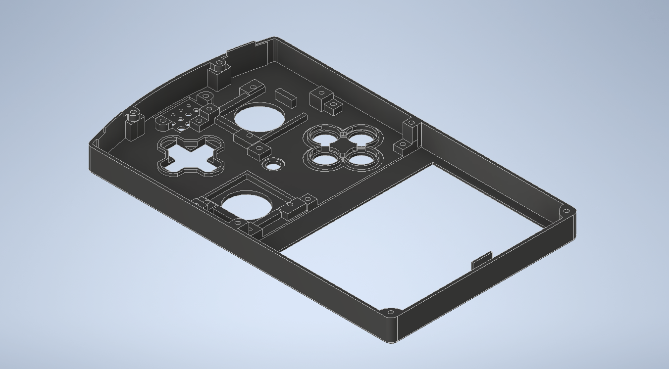
Front half of the case hasn't changed much. @supertazon just donated a version of the 3.5" screen that has tempered glass and a different bezel, so I'll be working that in at some point.
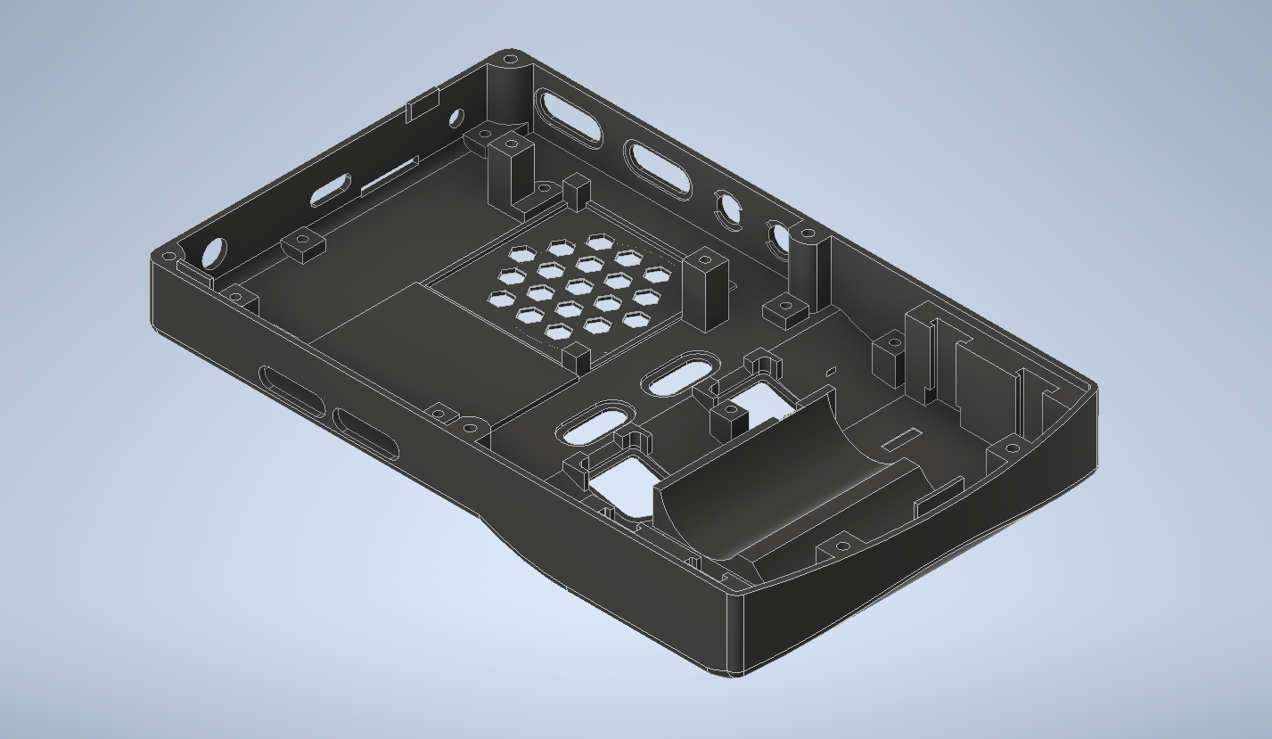
The back half has evolved a fair bit since the original WBC. Cleaner vents for intake/output, better triggers, and new screwposts for all the new boards are the biggest changes. I plan on tweaking the battery holders to use the same ones that Wesk used in the Ashida, as those will be a better fit for this case.
As of yesterday, all the circuit boards and a case have been ordered. I expect there to be some issues to iron out, so I look forward to doing that in a couple of weeks.
Once the design is all polished up and verified, I do plan on open sourcing it. It'll still be a difficult build, but it'll at least be up to date with modern components and (hopefully) be a very clean design. That release is likely several months out, so you'll have to be patient. More updates soon!
I stopped building Wiiboy Colors because I did not enjoy assembling the USB-C and old PMS boards needed to build them. Unfortunately, there just isn't enough space in the case to fit a PMS-2 and a PMS-PD inside, so I never bothered to do a redesign to use modern boards.
BUT with the aggressive LMAO trim, I can shift the Wii and cooling setup up ~6mm. This opens up just enough space for the PMS-2 to squeeze in between the cooling setup and the batteries. The PD board won't fit, but this change means that there's now enough space for the other 4LT boards.
My goal with this redesign is to integrate everything as cleanly as possible. Here's a breakdown of the 5 custom circuit boards that the redesign uses.
The Front Board
Very similar to the front board in the original WBC. Still uses DS Lite membranes/buttons and connectors for Switch joysticks, but it now has a footprint for the 4LT GC+ 2 to solder into. The design still features the FFC cable that goes between the two halves, although the video signals no longer run through it. While the FFC cable only looked super clean, I got pretty noticable screen interference when I ran everything over the cable. Screen wires will need to be run across the two halves manually, but I think that's for the best. Still only one speaker. There is space for two speakers to flank the dpad/c-stick, but I hate how that looks. I like the look of my one speaker setup, so that's how it's gonna stay for now.
The Main Back Board
The original WBC used two different boards for the top and bottom, but I've merged them into one board. The top half still houses the headphone jack, LED, and PD charging board. For now, I'm using the same $2 PD board that I used in my WiiVision. It's not really meant to be modular, but I'll try just soldering it directly to this board. Not the most elegant solution, but it'll allow for either 9v or 12v PD charging, which is all I really need. I've also implemented the GL823K microSD-USB chip for USB on the Wii. I've been using this chip on some of my Louiis for the past year, and it's the same chip that 4LT uses on the PD3. Really cool chip, and I've never run into any compatability issues with RVLoader, which is what I care about the most.
The bottom of the board still houses the triggers and MX chip circuitry. There's now a proper battery holder, which fits a 2016 coin cell battery. The bottom half also has pads/vias for three other circuit boards to latch onto.
Audio Board
The idea with this board was to have the headphone and digital audio signals running seperately from the power signals on the other board, with a solid ground plane between them to hopefully help mitgate interference on those lines. Uncertain whether this will help much, but we'll at least give it a shot. If interference is still bad, then there's still room to fit the open-source U-Amp circuit in the top board, but I'd like to avoid fine SMD assembly for these boards if I can.
Button Board
This board also uses castellated edges and runs along the other side of the board. Houses the tacts for power, volume control, and screen menus. I'm not in love with having this many buttons crammed into the side of the portable, so I'm considering implementing CrazyGadget's screen controls through GCC board to get rid of a few buttons.
PMS/ U-Amp Housing Board
You'll never guess what's on this board...
This board currently solders directly to the main bottom board, to bring all the audio and power signals to the bottom. I'd like to find some sort of connector to allow the two boards to come together and apart in a much nicer way. I'm currently using 0.1" header pins to mount them together, and the thinnest header pins connectors of this size still add up to over 7mm. I need something that can fit in the 2.6mm - 4.5mmish range. Any recommendations on things to implement to allow these boards to come apart conveniently would be great. This board also has a connector to go between @loopj 's Wii Power Strip project, so that there's almost no wires between the Wii and the power board.
Front half of the case hasn't changed much. @supertazon just donated a version of the 3.5" screen that has tempered glass and a different bezel, so I'll be working that in at some point.
The back half has evolved a fair bit since the original WBC. Cleaner vents for intake/output, better triggers, and new screwposts for all the new boards are the biggest changes. I plan on tweaking the battery holders to use the same ones that Wesk used in the Ashida, as those will be a better fit for this case.
As of yesterday, all the circuit boards and a case have been ordered. I expect there to be some issues to iron out, so I look forward to doing that in a couple of weeks.
Once the design is all polished up and verified, I do plan on open sourcing it. It'll still be a difficult build, but it'll at least be up to date with modern components and (hopefully) be a very clean design. That release is likely several months out, so you'll have to be patient. More updates soon!
