
Yes you need to connect both for full functionality, and fortunately you can daisy chain the I2C wires. What we recommend is to wire SCW/SDW from the Wii to the PMS, then run another pair of wires from the PMS SCW/SDW pads to the RVL-AMP/U-AMP. This will allow both boards their full functionalityOn this project, since you wire SCW and SDW from the PMS to the board with the RVL-AMP which then is wired to the wii, do you still also need to wire SCW and SDW directly from the PMS to the the wii?
Yeah this is normal. Basically all lines in an electrical circuit have a resistive connection to ground, including the primary voltages. It's a necessary part of electrical circuits to filter out noise and decouple the line. As long as the resistance is at least double digits, it's good. A single digit resistance indicates a short, which is bad.So I was testing the GC + 2.0 and connecting boards for shorts and found a connection between 3.3v and ground. However it had a very high resistance (1.7k) so I wanted to know if this was intended before I started re-soldering things.
No you still need to short Mode to 3.3v to get VGA out. The VGA patch only changes the HD output mode from yPbPr to VGA, you still need to use the Mode line to tell the Wii whether to output in SD or HDAm I correct in assuming that due to the software of rvloader forcing the wii to use vga, it is no longer necessary to wire 3.3v to mode on the wii?
Skibub28
.
- Joined
- May 28, 2023
- Messages
- 52
- Likes
- 13
So i was trying to solder the h and v sync pins but accidentally bridged a bunch of the pins. I've cleaned it up now but they still read on my multi-meter as shorted to each other. However, I noticed while testing other pins that I hadn't messed up around the same chip that I got the same readings. So I'm wondering which pins on that chip should have no resistance between each other and which ones I should worry about.
Is your multimeter showing a 0ohm or a 1ohm reading, or it it just beeping at you? Multimeters tend to beep at anything below 50ohms, which is a normal resistance range between some linesSo i was trying to solder the h and v sync pins but accidentally bridged a bunch of the pins. I've cleaned it up now but they still read on my multi-meter as shorted to each other. However, I noticed while testing other pins that I hadn't messed up around the same chip that I got the same readings. So I'm wondering which pins on that chip should have no resistance between each other and which ones I should worry about.
Skibub28
.
- Joined
- May 28, 2023
- Messages
- 52
- Likes
- 13
It's showing a 0ohm rating, my multimeter does not have a speaker built into it.Is your multimeter showing a 0ohm or a 1ohm reading, or it it just beeping at you? Multimeters tend to beep at anything below 50ohms, which is a normal resistance range between some lines
Skibub28
.
- Joined
- May 28, 2023
- Messages
- 52
- Likes
- 13
I also have it doing weird things with the power. It turns on when I flip the switch to the on position, but stays on when I flip it back to off, it then turns off when I flip it back to on and stays off when I switch it to off from there. Only then if I flip it on it will turn on. I essentially have to flip the switch twice to get it to change from off to on.
I found a diagram for the AVE. It's in the 6 layer board orientation tho, so rotate it 180 degrees to match a 4 layer Wii.
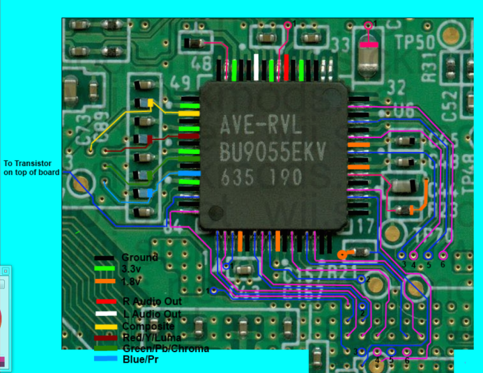
All thick lines of the same colour should have continuity. Lines of different colours should not, and pins 33 and 34 definitely should not.
All thick lines of the same colour should have continuity. Lines of different colours should not, and pins 33 and 34 definitely should not.
That's normal, the PMS ships with the power on/off mode configured for a momentary button. For the Ashida's switch to work correctly you have to go into the RVLoader settings for the PMS and change the momentary button mode to latching switch mode.I also have it doing weird things with the power. It turns on when I flip the switch to the on position, but stays on when I flip it back to off, it then turns off when I flip it back to on and stays off when I switch it to off from there. Only then if I flip it on it will turn on. I essentially have to flip the switch twice to get it to change from off to on.
Skibub28
.
- Joined
- May 28, 2023
- Messages
- 52
- Likes
- 13
I've got the screen and vga working and have moved on to usb. Tough i've wired up d+ and d- and 5v to the wii it says that it still can't detect the usb drive. I know the drive works with the wii since I was tested it before trimming the wii. I've tried looking for solutions here but the search says usb is to short or common and doesn't include it in the results. I'm unable to take pictures so I'd appreciate it if I could have a list or link to a list of possible things that could go wrong that I can go through. (I'm so sorry this post is no help in providing the information you guys need to help me but I didn't know what else to do)
Without seeing the wiring we can't really provide any support. All I can suggest is that you should double check that you have wired D+ and D- to the correct vias by doing a continuity check with your multimeter. In the Trimming Guide diagrams the grey USB pins are D- and the green ones are D+. Pins 3 and 2 are a pair, and pins 7 and 6 are a pair. Make sure you've only run your data wires to one of the pairs, and if everything is wired correctly then you can try wiring to the other pair instead.
Any reason why you can't provide any photos?
Any reason why you can't provide any photos?
Skibub28
.
- Joined
- May 28, 2023
- Messages
- 52
- Likes
- 13
My phone camera sucks (wouldn't be able to see anything small) and has to be plugged in to a computer to upload photos so I'd have to borrow someone else's phone which I currently can't do. I will get photos as soon as possible. I have checked with a multimeter and D+ and D- are wired to the correct vias. Do you need to wire up 5v to the wii for usb as well?
Nah the Wii itself doesn't need 5v for anything. Only the USB needs 5v, which is delivered to the PD's UP pad via the PMS' UP pad.
Actually that reminds me of something. If you're using a USB drive that's super flat like the Kingston FCR-MRG2 and can fit into the USB port both ways, make sure that you've plugged it in with the correct orientation. The contacts of the USB drive should be facing up away from the PD PCB
Actually that reminds me of something. If you're using a USB drive that's super flat like the Kingston FCR-MRG2 and can fit into the USB port both ways, make sure that you've plugged it in with the correct orientation. The contacts of the USB drive should be facing up away from the PD PCB
Skibub28
.
- Joined
- May 28, 2023
- Messages
- 52
- Likes
- 13
To get usb working I had to wire UP to 5v on the PMS as Up on the pms was only giving 3.3v. But then the fan stopped working. I messed around with it and now for a while the fan would work if connected to 5v. Now F+ is under powered (1.8v) and I'm not getting any reading out of 5V. Should I just assume this section of the pms board is dead? Is there a fix? Or another way to supply usb and the fan with power>
Without visual inspection, this kind of fault is nearly impossible to diagnose. It sounds like somehow one or more regulators have been damaged, which won't be easy to diagnose the root cause of and fix. What I will suggest in the meantime is to desolder all the wires on the PMS and PD, clean the boards with isopropyl alcohol and a toothbrush, then reconnect the battery and test the voltages again.