
Worklog Fusion64
- Thread starter Noah
- Start date
I'm curious to see your cooling method.
Hopefully before March, but due to the coronavirus outbreak in China it's going to be difficult getting boards made, at least during this month. I will be sure to update everyone as the release draws closer. As far a pricing goes I'm not entirely sure, but I'm aiming for ~$20 for the entire kit (both PCBs and a flex cable. the slot will come presoldered).Those pcbs looks like everything I've ever needed in my life. Any idea when they'll be available and for how much ~?
There are a number of open source analog converters available out on the internet. Most of them just use a small packaged microcontroller and can easily be programmed for the switch sticks. Then you'd need a breakout board since the sticks can't be soldered to directly. However that method is only good if you're using a first party controller. I think I'll be using an N64+ replacement controller board...Hello @Noah
I’m curious to see how you’ll use the joycons analog stick with the n64, if you dont mind, when you reach that stage, can you show some information about how you did it and what you needed to do it?

I might end up using a first party controller in a prototype build however. Since the coronavirus will cause delays in manufacturing of PCBs, I think I might build two units; one to test and make sure the dimensions are correct and to verify the controller PCBs I'll be ordering from OSH park, and another that will be the "true" final build for this project. Printed in white, wetsanded and matched to the original.
The N64 can be passively cooled. depending on how close to the back it's mounted there will be a lot of room between the N64 and the screen driver board (like close to 20mm) so I don't think I'll need a fan. On the original, Ashen placed vents along the bottom and I think I'll mostly do something similar, however since the top will most likely only contain a power button I will probably end up putting a few vent holes up there as well so that air can pass through the entire console from top/bottom or vice versa and not get trapped inside.I'm curious to see your cooling method.
- Joined
- May 10, 2019
- Messages
- 19
- Likes
- 9
I cant wait to buy one of these..I cant wait to build one of these
Spent a bit of time today working on PCBs and tweaking the case.
First off, I started by making a mount for the screen driver board as well as UltraVGA. This will be pressed right up to the LCD so that it will hold it in place while also providing me with screw posts in order to be easily able to remove the driver board or UltraVGA if need be.
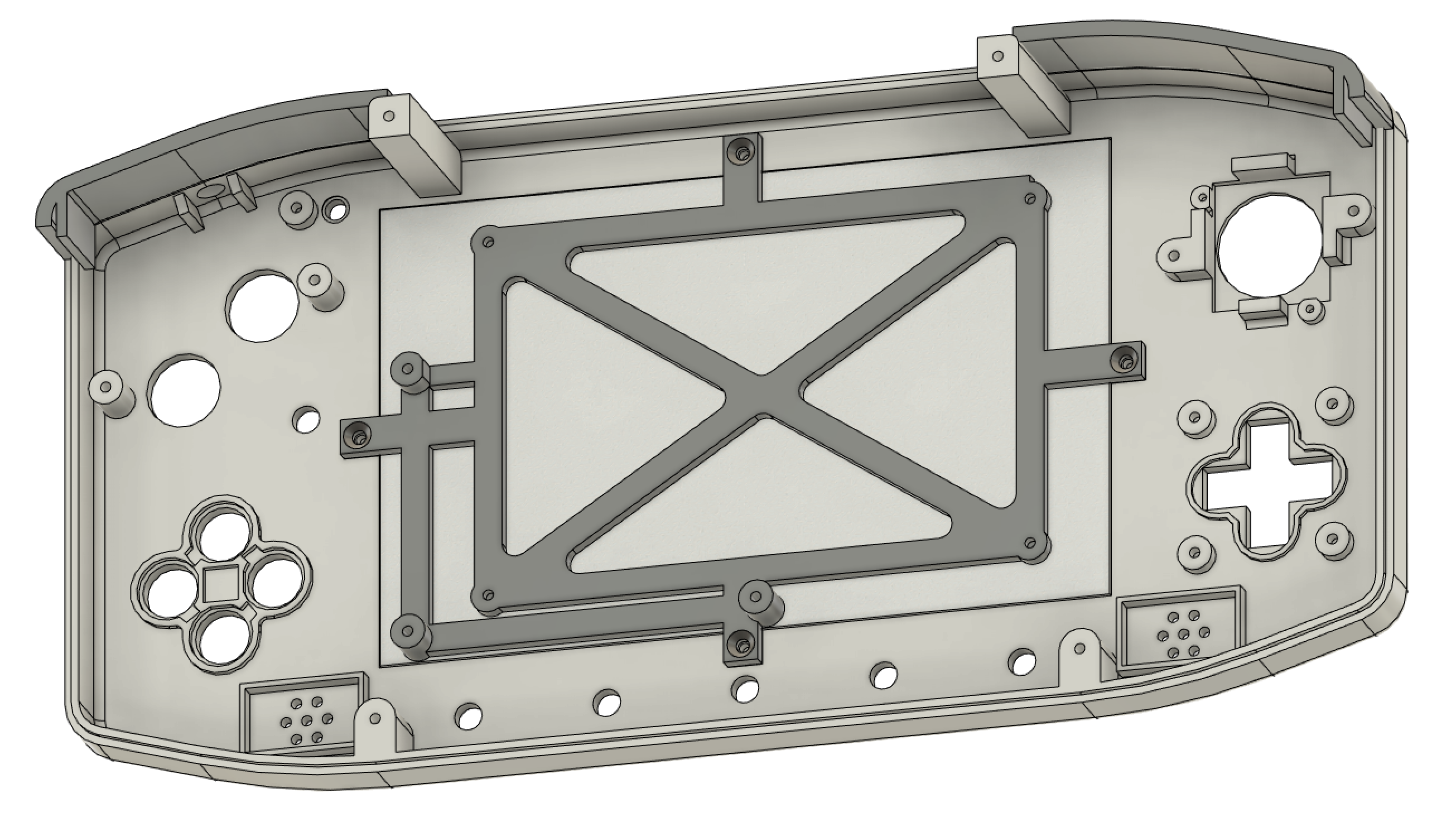
As you might be able to tell from the images, I've also cloned Gman's shoulder button setup from the G-Wii for use in this portable. I had thought about employing a hinged setup for the triggers, but this setup uses much less space and feels pretty close to that. Once I do a full print of the case I will be able to thoroughly test it and make sure it feels good enough, otherwise I will most likely tweak the design to incorporate a hinge but for now this will do.")
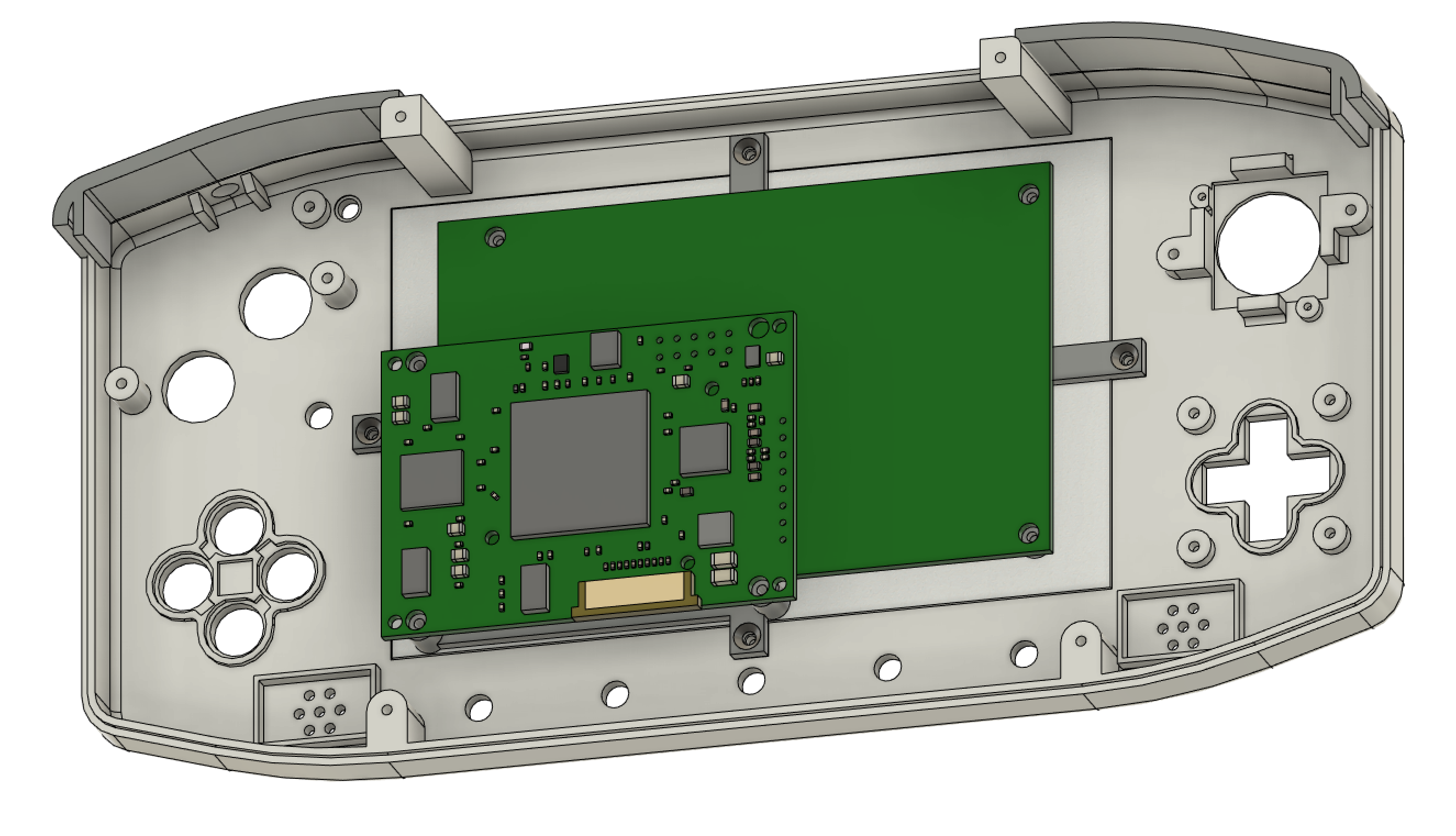
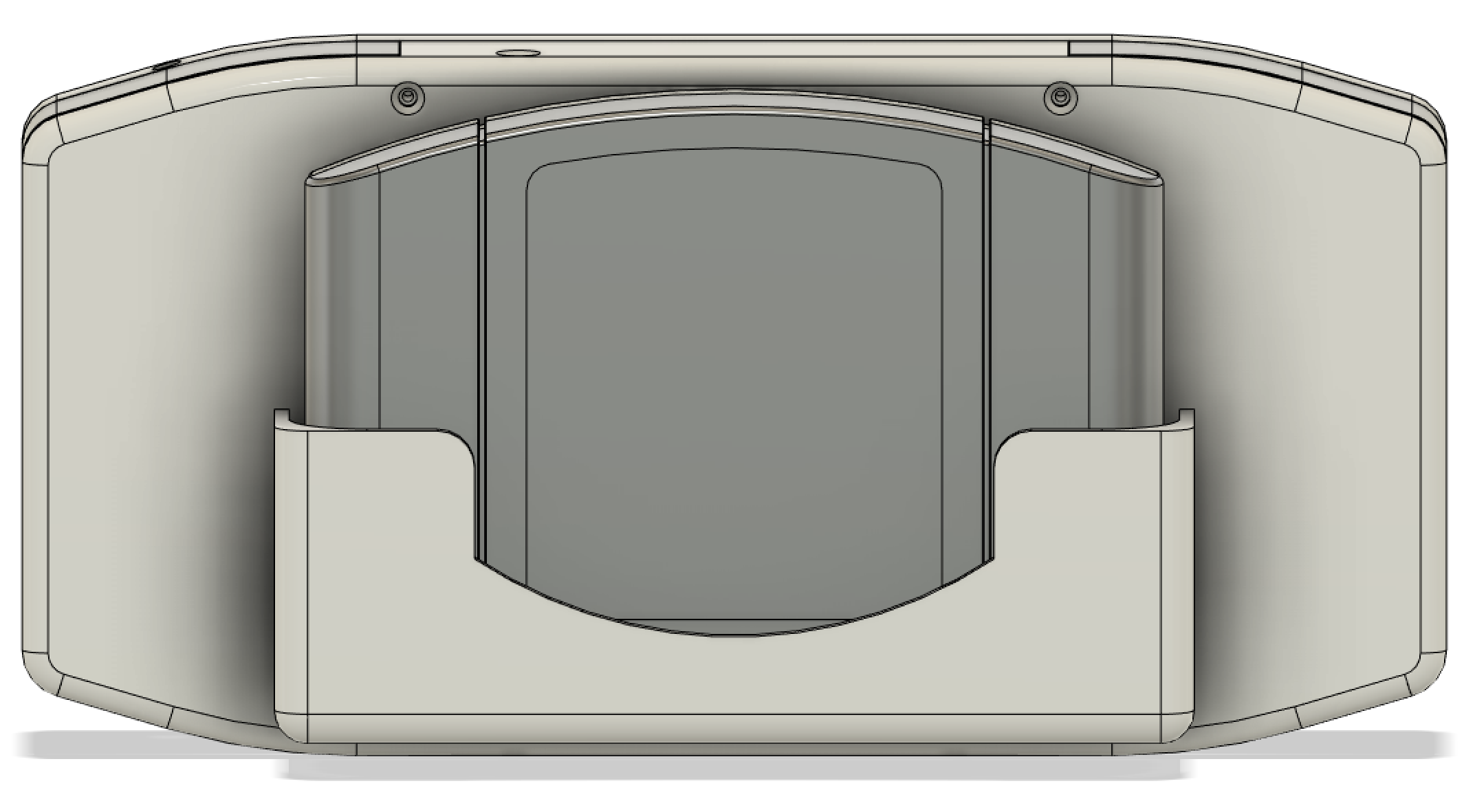
I've also been spending a bit of time trying to find a good way to remove the expansion pak slot from the motherboard while being able to trim the board below the pins off. To better show what I'm talking about, here's an image of the N64 as it currently sits in the case.
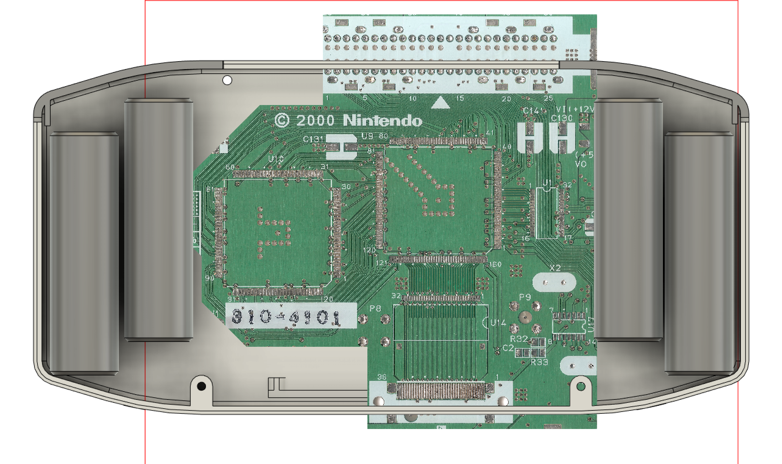
As you can see, currently in order to make room for the upper screw posts, I'll need to perform the board bend (which has always been the plan) however I will need to move the motherboard down a few mm in order to ensure there's enough space for everything to clear. To do this I will be removing the expansion pak slot from the board and attempting to find a suitable solution to replace it. I've tried to relocate the passives from the jumper pak a couple of times with no luck.
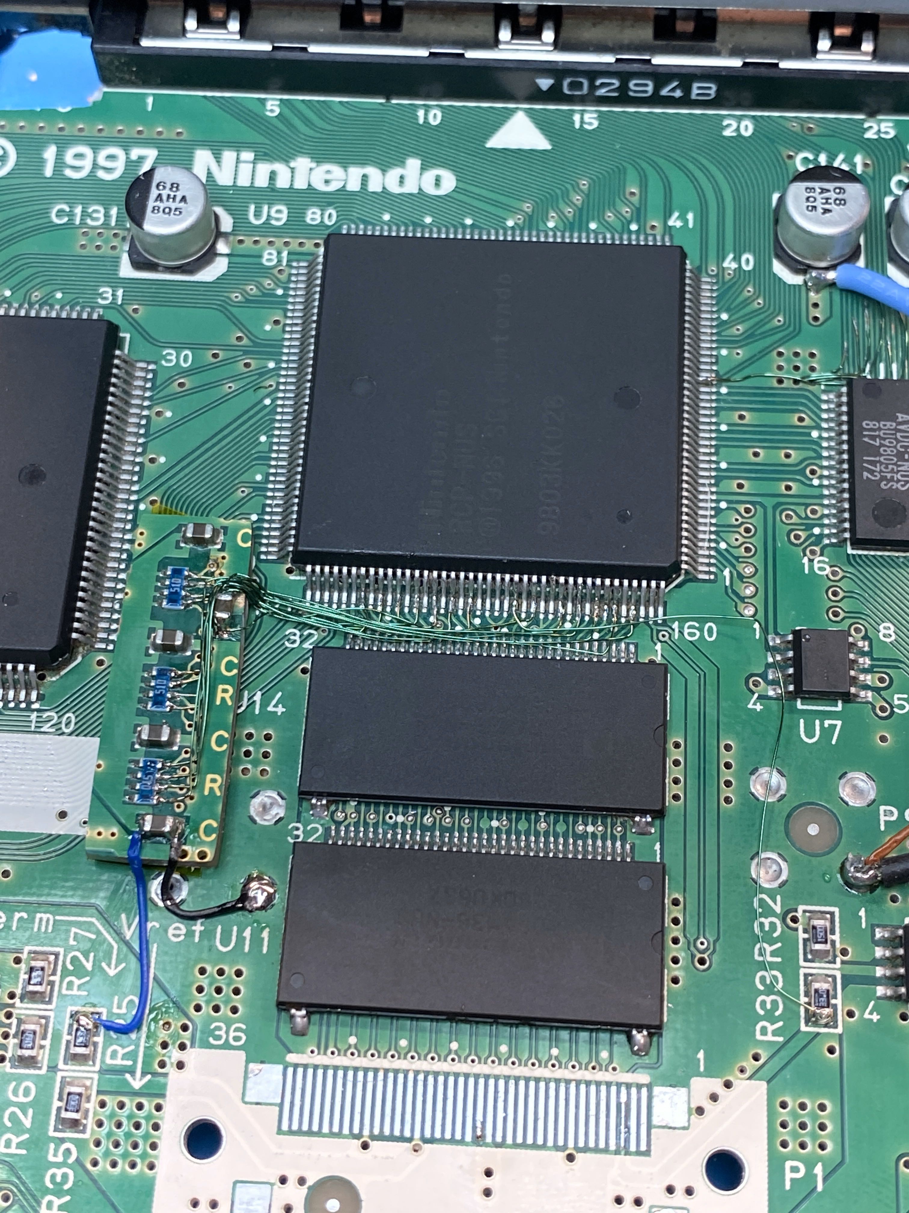
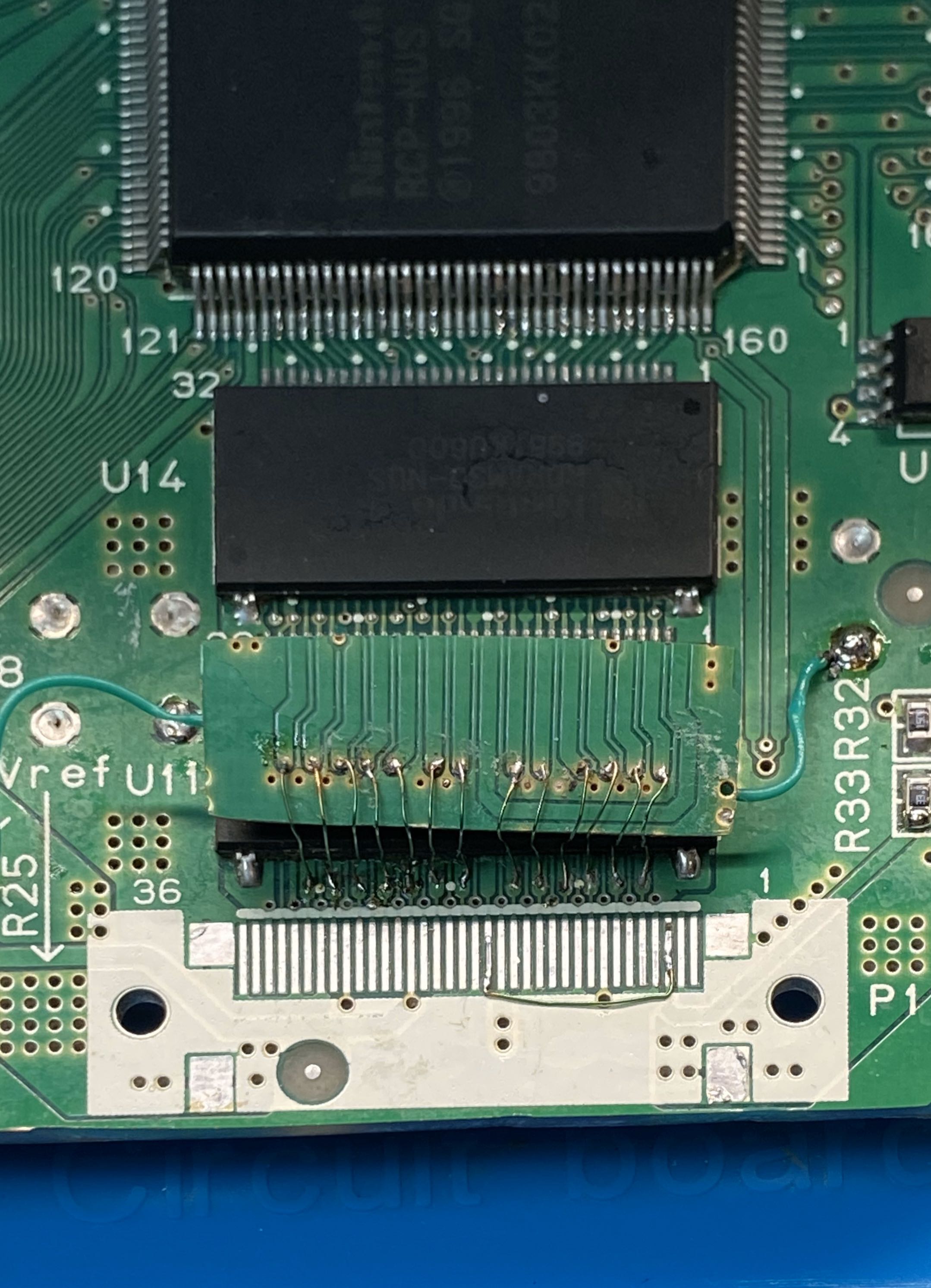
This was my first attempt, and because I'm not terribly familiar with how the RDRAM on the N64 works I thought it would be worth a shot to try and terminate the rambus from the RCP. Unsurprisingly it didn't work, so I asked Marshall who pointed out however that the termination resistors need to lead to Vterm with minimal impedance. So I desoldered everything and tried again, which resulted in the setup seen below:
Unfortunately this still didn't work, and so I resoldered the slot onto the board and still didn't get it to boot. At this point I'm convinced that during my Frankenstein-ish experiments I might have killed the board, but I haven't yet lifted the PIF relocation from the other side of the board to verify that all of the connections are in tact (since I hot aired the slot off in the first place it's possible that something came loose). However, I'll need to trim another board regardless, so what I've done is come up with a flex PCB that sits on top of the pins in the picture above and it should hopefully work.
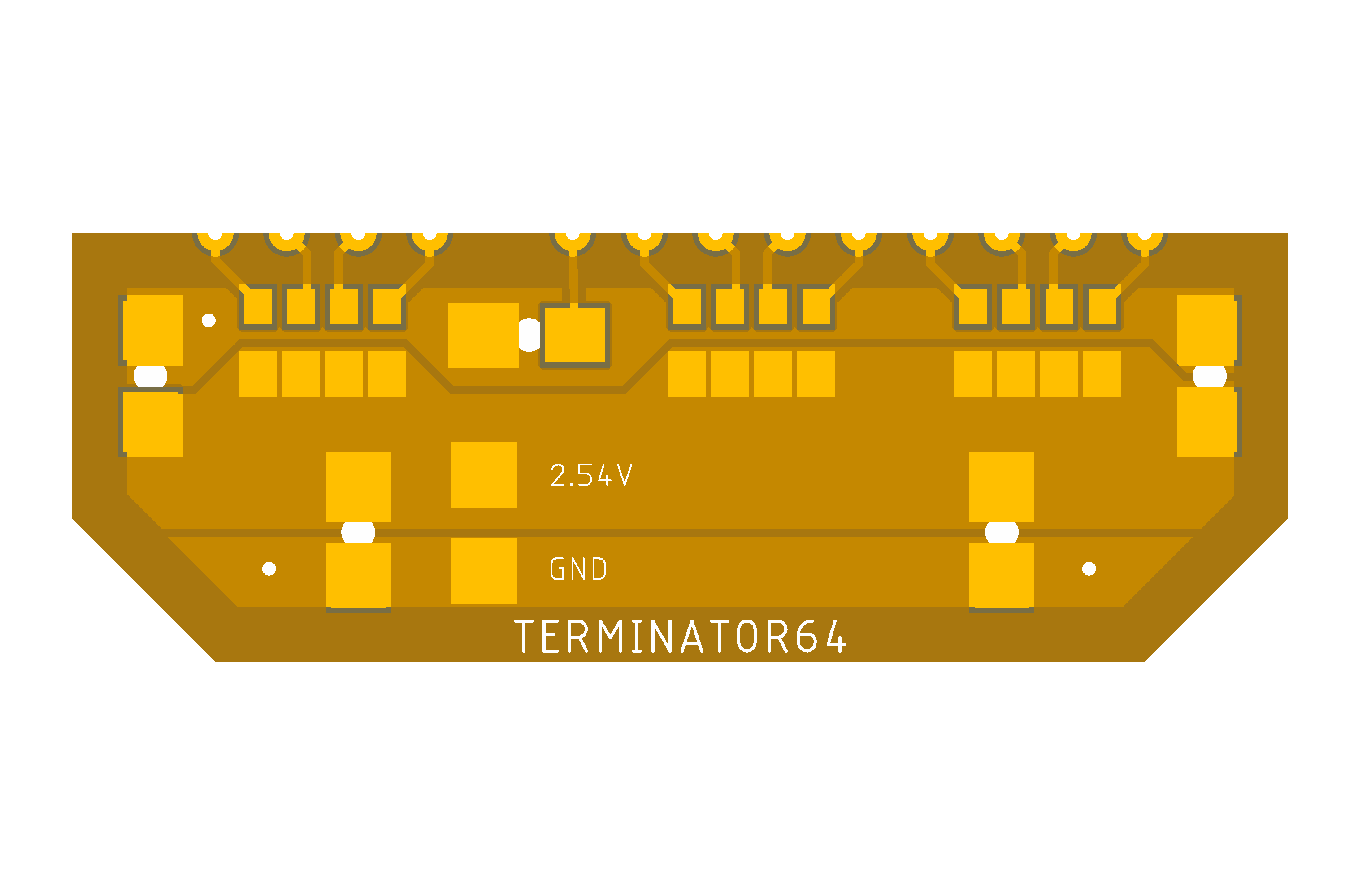
If the board works I'll make a few tweaks to the design and probably put it in the store. I'd like to grab Vterm and ground from the slot pins themselves, but due to the fabs limitations I just wanted to verify that something like this is possible to begin with before doing anything more advanced than this. I should hopefully have the flex boards within a couple weeks time and will be able to verify whether or not the design will work.
Finally, I've modeled the cart slot cover on the back of the case.
Since the cover will cover (lol) the bottom two screw posts that will hold the portable together, I've made the cover be a snap fit design that clips into the back housing. Thanks to SixtyFlex as seen in one of my previous posts, that means that the entire cart slot will be able to be released from the unit by unclipping the cover from the back half and releasing the FFC connector on the PCB. This will make it extremely easy to swap out the cart slot if it's ever needed since it won't be buried in the case behind the motherboard and other circuitry!
That's all I've got for now in terms of updates. The design is very close to being done so once I finalize the controller PCBs I will go ahead and print the case while I'm waiting for them to arrive. I should be able to verify basically everything once I have the print in hand so that by the time the PCBs arrive I can put a unit together as a "prototype" build before building the final one I'll be bringing to MGC.
First off, I started by making a mount for the screen driver board as well as UltraVGA. This will be pressed right up to the LCD so that it will hold it in place while also providing me with screw posts in order to be easily able to remove the driver board or UltraVGA if need be.
As you might be able to tell from the images, I've also cloned Gman's shoulder button setup from the G-Wii for use in this portable. I had thought about employing a hinged setup for the triggers, but this setup uses much less space and feels pretty close to that. Once I do a full print of the case I will be able to thoroughly test it and make sure it feels good enough, otherwise I will most likely tweak the design to incorporate a hinge but for now this will do.
I've also been spending a bit of time trying to find a good way to remove the expansion pak slot from the motherboard while being able to trim the board below the pins off. To better show what I'm talking about, here's an image of the N64 as it currently sits in the case.
As you can see, currently in order to make room for the upper screw posts, I'll need to perform the board bend (which has always been the plan) however I will need to move the motherboard down a few mm in order to ensure there's enough space for everything to clear. To do this I will be removing the expansion pak slot from the board and attempting to find a suitable solution to replace it. I've tried to relocate the passives from the jumper pak a couple of times with no luck.
This was my first attempt, and because I'm not terribly familiar with how the RDRAM on the N64 works I thought it would be worth a shot to try and terminate the rambus from the RCP. Unsurprisingly it didn't work, so I asked Marshall who pointed out however that the termination resistors need to lead to Vterm with minimal impedance. So I desoldered everything and tried again, which resulted in the setup seen below:
Unfortunately this still didn't work, and so I resoldered the slot onto the board and still didn't get it to boot. At this point I'm convinced that during my Frankenstein-ish experiments I might have killed the board, but I haven't yet lifted the PIF relocation from the other side of the board to verify that all of the connections are in tact (since I hot aired the slot off in the first place it's possible that something came loose). However, I'll need to trim another board regardless, so what I've done is come up with a flex PCB that sits on top of the pins in the picture above and it should hopefully work.
If the board works I'll make a few tweaks to the design and probably put it in the store. I'd like to grab Vterm and ground from the slot pins themselves, but due to the fabs limitations I just wanted to verify that something like this is possible to begin with before doing anything more advanced than this. I should hopefully have the flex boards within a couple weeks time and will be able to verify whether or not the design will work.
Finally, I've modeled the cart slot cover on the back of the case.
Since the cover will cover (lol) the bottom two screw posts that will hold the portable together, I've made the cover be a snap fit design that clips into the back housing. Thanks to SixtyFlex as seen in one of my previous posts, that means that the entire cart slot will be able to be released from the unit by unclipping the cover from the back half and releasing the FFC connector on the PCB. This will make it extremely easy to swap out the cart slot if it's ever needed since it won't be buried in the case behind the motherboard and other circuitry!
That's all I've got for now in terms of updates. The design is very close to being done so once I finalize the controller PCBs I will go ahead and print the case while I'm waiting for them to arrive. I should be able to verify basically everything once I have the print in hand so that by the time the PCBs arrive I can put a unit together as a "prototype" build before building the final one I'll be bringing to MGC.
Attachments
-
 1.5 MB Views: 276
Such an amazing progress, your trial and error might've killed the board but man, this is such a valuable information! i hope it goes well with your flex plan since everything works with flex cables. I'm really looking forward for this, this is a winner.Spent a bit of time today working on PCBs and tweaking the case.
First off, I started by making a mount for the screen driver board as well as UltraVGA. This will be pressed right up to the LCD so that it will hold it in place while also providing me with screw posts in order to be easily able to remove the driver board or UltraVGA if need be.
View attachment 10551
View attachment 10550
As you might be able to tell from the images, I've also cloned Gman's shoulder button setup from the G-Wii for use in this portable. I had thought about employing a hinged setup for the triggers, but this setup uses much less space and feels pretty close to that. Once I do a full print of the case I will be able to thoroughly test it and make sure it feels good enough, otherwise I will most likely tweak the design to incorporate a hinge but for now this will do.
I've also been spending a bit of time trying to find a good way to remove the expansion pak slot from the motherboard while being able to trim the board below the pins off. To better show what I'm talking about, here's an image of the N64 as it currently sits in the case.
View attachment 10553
As you can see, currently in order to make room for the upper screw posts, I'll need to perform the board bend (which has always been the plan) however I will need to move the motherboard down a few mm in order to ensure there's enough space for everything to clear. To do this I will be removing the expansion pak slot from the board and attempting to find a suitable solution to replace it. I've tried to relocate the passives from the jumper pak a couple of times with no luck.
View attachment 10555
This was my first attempt, and because I'm not terribly familiar with how the RDRAM on the N64 works I thought it would be worth a shot to try and terminate the rambus from the RCP. Unsurprisingly it didn't work, so I asked Marshall who pointed out however that the termination resistors need to lead to Vterm with minimal impedance. So I desoldered everything and tried again, which resulted in the setup seen below:
View attachment 10556
Unfortunately this still didn't work, and so I resoldered the slot onto the board and still didn't get it to boot. At this point I'm convinced that during my Frankenstein-ish experiments I might have killed the board, but I haven't yet lifted the PIF relocation from the other side of the board to verify that all of the connections are in tact (since I hot aired the slot off in the first place it's possible that something came loose). However, I'll need to trim another board regardless, so what I've done is come up with a flex PCB that sits on top of the pins in the picture above and it should hopefully work.
View attachment 10549
If the board works I'll make a few tweaks to the design and probably put it in the store. I'd like to grab Vterm and ground from the slot pins themselves, but due to the fabs limitations I just wanted to verify that something like this is possible to begin with before doing anything more advanced than this. I should hopefully have the flex boards within a couple weeks time and will be able to verify whether or not the design will work.
Finally, I've modeled the cart slot cover on the back of the case.
View attachment 10552
Since the cover will cover (lol) the bottom two screw posts that will hold the portable together, I've made the cover be a snap fit design that clips into the back housing. Thanks to SixtyFlex as seen in one of my previous posts, that means that the entire cart slot will be able to be released from the unit by unclipping the cover from the back half and releasing the FFC connector on the PCB. This will make it extremely easy to swap out the cart slot if it's ever needed since it won't be buried in the case behind the motherboard and other circuitry!
That's all I've got for now in terms of updates. The design is very close to being done so once I finalize the controller PCBs I will go ahead and print the case while I'm waiting for them to arrive. I should be able to verify basically everything once I have the print in hand so that by the time the PCBs arrive I can put a unit together as a "prototype" build before building the final one I'll be bringing to MGC.
I've finished working on the PCBs for the portable. I've ordered each of them, so hopefully I should be able to put a unit together soon.
The A/B board as seen here features a N64+ on the back! @Gman and I will be using our MGC portables to test a new firmware for @Aurelio which will hopefully result in a N64+ board being available on the store soon. No more killing 1st party controllers!
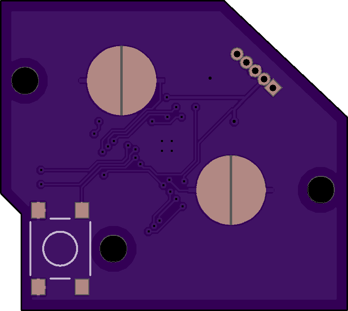
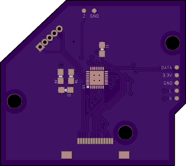
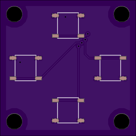
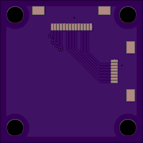
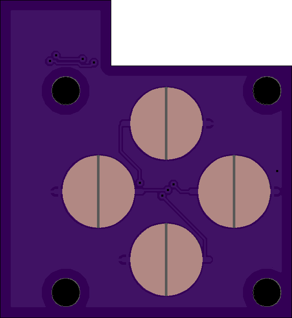
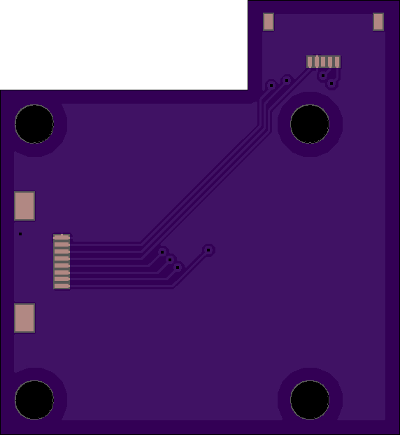
As you can probably guess, all of the controller PCBs in this portable will be connected by FFC cables! This means no manual wiring for the controller portion of the build which should speed up assembly time by a considerable amount.
The A/B board as seen here features a N64+ on the back! @Gman and I will be using our MGC portables to test a new firmware for @Aurelio which will hopefully result in a N64+ board being available on the store soon. No more killing 1st party controllers!
As you can probably guess, all of the controller PCBs in this portable will be connected by FFC cables! This means no manual wiring for the controller portion of the build which should speed up assembly time by a considerable amount.
Don't you have to wire up those connectors tho? Or is that less intensive work than wiring up a controller? Sorry not familiar with n64
I absolutely cannot wait for the N64+I've finished working on the PCBs for the portable. I've ordered each of them, so hopefully I should be able to put a unit together soon.
The A/B board as seen here features a N64+ on the back! @Gman and I will be using our MGC portables to test a new firmware for @Aurelio which will hopefully result in a N64+ board being available on the store soon. No more killing 1st party controllers!
As you can probably guess, all of the controller PCBs in this portable will be connected by FFC cables! This means no manual wiring for the controller portion of the build which should speed up assembly time by a considerable amount.
Thank you guys for doing this.
And great job @Noah
- Joined
- Nov 10, 2016
- Messages
- 606
- Likes
- 1,625
Looking forward to N64+ as well. I actually got around to testing some stuff for my own N64p a few days ago but the 3rd party controller I chopped up wasn't being recognized. Went out and found a cheap Mad Catz at Goodwill. Still, I probably won't make any additional progress before the BitBuilt solution is available.
Noah uses EAGLE iirc. It's nice because it's free for students. Another alternative is KiCAD which is free/open source. JLCPCB is generally a great option for ordering PCBs. Their boards are high quality and very cheap. For tiny, low quantity PCBs I tend to go with OSH Park because while the price per square inch is considerably higher they offer free shipping which makes it a better option for small area boards.Damn those PCBs look slick. Are you using EAGLE to make them? I haven't any experience designing PCBs but have a heavy background in CAD modelling (for school and work) and I'm super curious about learning the program. @Noah on another note, where do you order PCBs from?
Cool thanks for the reply. Ive had my Fusion360 student account for a while now even though I graduated 2 years ago, so I'll see if I can also get a copy of EAGLE along with it, my student email never expires so I should be good. I'll look into those PCBs makers, I'm in Canada so I'm sure regardless the shipping to me is gonna suck.Noah uses EAGLE iirc. It's nice because it's free for students. Another alternative is KiCAD which is free/open source. JLCPCB is generally a great option for ordering PCBs. Their boards are high quality and very cheap. For tiny, low quantity PCBs I tend to go with OSH Park because while the price per square inch is considerably higher they offer free shipping which makes it a better option for small area boards.