Worklog Nintendo Wii Classic Edition

Joined
Nov 13, 2022
Messages
180
Likes
53
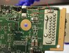
Hey everyone! This is the worklog for my next project, the Nintendo Wii Classic Edition. The idea behind this project is basically a modified version of Nold's Wii Micro, but stuffed inside a perfect replica (scale TBD) 3D printed Wii case.
Untitled_Artwork.jpg

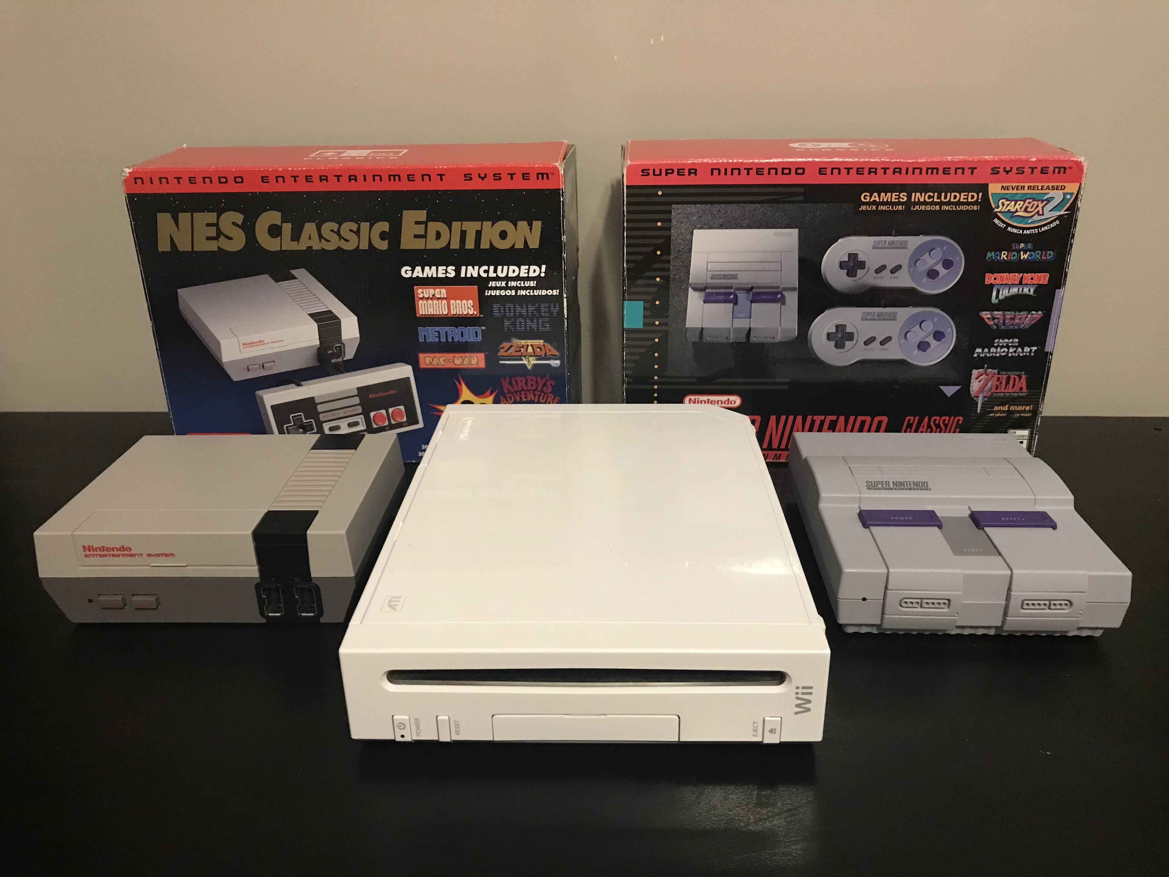
It will include several extra features as well that can be found in the other Nintendo Classic Edition consoles such as HDMI video out and internal storage (I'll explain how I plan to achieve those later). It will use the same board and trim as the original Wii Micro, and incorporate similar features such as GameCube Controller support, Bluetooth, and the MX Chip. A couple extra features I'd like to add include an integrated sensor bar (probably just a 3rd party sensor bar wired up to the orignal port and placed on the front of the system), and an extra port on the front of the console (inside where the SD card slot would be on a normal Wii) that can be used to access the internal USB drive. Since we're back in the school year, I don't know how often I'll be able to post, but I’ll keep you all updated as much as I can! Wish me luck!
 
Last edited:
Joined
Nov 13, 2022
Messages
180
Likes
53
Alright, I'm about to start trimming the board, but I want to make sure I have done all the pre-cutting prep first. I marked out the trim line along the board (following the image shown on Nold's forum), installed RVLoader and confirmed that everything is working.
IMG_2655.jpg

IMG-3728.jpg


Am I missing any steps? Is there anything I should be aware of while trimming? I'm a little nervous because last time I tried to trim a board, I must've made a mistake because the board never booted and we couldn't diagnose the issue. Also, any advice regarding the removal of the Memory Card slot without a hot air rework station?
 
  • Like
Reactions: E64

Stitches

2 and a Half Dollarydoos
Staff member
.
.
Joined
Feb 5, 2017
Messages
3,853
Likes
3,026
Location
Banana Bender Land, Australia
Portables
6
Alright, I'm about to start trimming the board, but I want to make sure I have done all the pre-cutting prep first. I marked out the trim line along the board (following the image shown on Nold's forum), installed RVLoader and confirmed that everything is working.
View attachment 29895
View attachment 29896

Am I missing any steps? Is there anything I should be aware of while trimming? I'm a little nervous because last time I tried to trim a board, I must've made a mistake because the board never booted and we couldn't diagnose the issue. Also, any advice regarding the removal of the Memory Card slot without a hot air rework station?
If you don't want to destroy the ports:
  • Get a good quality solder sucker, like an Engineer SS-02
  • Add extra solder to the pins with your iron cranked to at least 380 degrees celsuis
  • Heat the solder blob for a pin thoroughly before going for the bigg succ, making sure the iron remains in contact with the blob during the bigg succ
  • Once the succ is done, use the iron tip to push the pin itself so that it's not stuck to the side of the through hole and can wiggle freely
Do that for all of the pins and anchors, and the memcard slots will just lift out
 
Joined
Nov 13, 2022
Messages
180
Likes
53
All done! It might not have been the prettiest job, but when comparing it to my last attempt at desoldering a memory card slot,
123DC480-3D54-4283-A8D3-AAB798BADA0A.png
I’d say it went well. Most importantly of all, everything still boots as normal.
8F7B8BC1-BF15-4C08-8BC6-E13386B01AC5.jpeg

Now it’s on to the most dreaded step: trimming. Can anyone confirm whether the trim line I have drawn is correct or not? Also, any last words of wisdom before I embark on this dangerous journey?
 

Stitches

2 and a Half Dollarydoos
Staff member
.
.
Joined
Feb 5, 2017
Messages
3,853
Likes
3,026
Location
Banana Bender Land, Australia
Portables
6
The lines look fine to me. Just make sure you trim on the outside edge of the lines to give yourself plenty of room to sand (6 layers need more sanding)
 
Joined
Nov 13, 2022
Messages
180
Likes
53
And it’s done! I’d say that went pretty well for the most part (ignore how MASSIVE the MX Chip is). Cuts are outside the lines and everything is sanded down buttery smooth.
47757843-F13B-4719-841C-B2638242A539.jpeg

Before moving on though, I need to make sure the curse of bad trims isn’t still haunting me. Can I check the resistances of this in the same way you’d test a portable trim?
 

Stitches

2 and a Half Dollarydoos
Staff member
.
.
Joined
Feb 5, 2017
Messages
3,853
Likes
3,026
Location
Banana Bender Land, Australia
Portables
6
And it’s done! I’d say that went pretty well for the most part (ignore how MASSIVE the MX Chip is). Cuts are outside the lines and everything is sanded down buttery smooth.
View attachment 29926
Before moving on though, I need to make sure the curse of bad trims isn’t still haunting me. Can I check the resistances of this in the same way you’d test a portable trim?
Yeah you can. The exact numbers will be different, but the proportions are what tell the tale
 
Joined
Nov 13, 2022
Messages
180
Likes
53
Okay, so while I was cleaning up the board (re-sanding, removing partially cut through components, etc.) I noticed a mistake I’d made. While cutting with the demel, I must’ve accidentally grazed the surface of the board, leaving this exposed bit on its surface.
4249624F-D3C2-4B28-B0BF-58D8A2C46FAD.jpeg
I know it goes slightly inside the trim line, but would I be able to sand in there and remove that part of the board, or is it alright and I should just leave it as is?
 

CrazyGadget

Crazy Helpful, CrazyGadget
.
Joined
Jun 6, 2020
Messages
612
Likes
882
Location
Downing's Closet
Portables
???
That's perfectly fine as is, you just grazed the soldermask layer off. If you had burned through the copper layer and into the second layer, that could have been at risk for shorting, but such isn't the case here!
 
Joined
Nov 13, 2022
Messages
180
Likes
53
That's perfectly fine as is, you just grazed the soldermask layer off. If you had burned through the copper layer and into the second layer, that could have been at risk for shorting, but such isn't the case here!
Thank goodness (for both that and the quick reply)! Are there any other potential short-causing things I should be aware if? I’m super paranoid because of the undiagnosable short issue with my portable.
 

CrazyGadget

Crazy Helpful, CrazyGadget
.
Joined
Jun 6, 2020
Messages
612
Likes
882
Location
Downing's Closet
Portables
???
Keep your board clean of flux, stray solder balls / blobs, wire, or any other FOD. Keep exposed wire short enough to cover a joint and no longer. Always sanity check before applying power (usually using a multimeter to check resistances / continuity of whatever you're working on)...

Regarding the portable, do you have a worklog or anything? Perhaps we could diagnose that issue as well, but that's for another thread.
 
Joined
Nov 13, 2022
Messages
180
Likes
53
Regarding the portable, do you have a worklog or anything? Perhaps we could diagnose that issue as well, but that's for another thread.
Only the s-Wii-ch worklog. If you have any suggestions for fixes we haven’t tried yet, I’d be happy to hear them!
 
Joined
Nov 13, 2022
Messages
180
Likes
53
Maybe I’m an idiot, but I can’t figure out what settings I should have the multimeter on to check the resistances. Any advice?

7F58AE38-67F2-4C52-A5AA-AD0B2301C493.jpeg
 
Joined
Nov 13, 2022
Messages
180
Likes
53
Okay, the tallies are in. Resistances have been checked, and the final result is, no shorts! I appear to be free from the curse, because every resistance was at least relatively near to its intended value. Here are the tables, one with the values I got and one with the values of a working trim of the same model (thanks guyman70718).
IMG-3755.jpg1696279625045-45443a32-9ab6-452b-bec7-2e7a952aefd2_1.jpg
Like I said, everything is pretty close with the exception of the 3.3v measurements. According to guyman70718's measurements, they should all be closer to 8 instead of 6 as I have them. Is that going to make a difference or will it function the same?
 

CrazyGadget

Crazy Helpful, CrazyGadget
.
Joined
Jun 6, 2020
Messages
612
Likes
882
Location
Downing's Closet
Portables
???
I'm wondering if the calibration on your DMM is just really shotty... The pic of guyman's table is referencing an OM6 trim (6 layer mobo) which has much smaller resistances on some of the lines, notable 1v. You should be getting around 130 ohms on the 1v line, 45 ohms on the 1v15 line, 36 ohms on the 1v8 line, and 3v3 tends to jump around, but as long as you're in the kOhms, it should be fine.
 
Top