Worklog Nintendo Wii Classic Edition

Joined
Nov 13, 2022
Messages
180
Likes
53
I'm wondering if the calibration on your DMM is just really shotty... The pic of guyman's table is referencing an OM6 trim (6 layer mobo) which has much smaller resistances on some of the lines, notable 1v. You should be getting around 130 ohms on the 1v line, 45 ohms on the 1v15 line, 36 ohms on the 1v8 line, and 3v3 tends to jump around, but as long as you're in the kOhms, it should be fine.
How do I check that it’s in kOhms?
 

CrazyGadget

Crazy Helpful, CrazyGadget
.
Joined
Jun 6, 2020
Messages
618
Likes
905
Location
Downing's Closet
Portables
???
If you have it on the 20k setting, it represents kOhms. So if it says 5.2 on the 20k setting, it's 5.2k (just an example).
 

CrazyGadget

Crazy Helpful, CrazyGadget
.
Joined
Jun 6, 2020
Messages
618
Likes
905
Location
Downing's Closet
Portables
???
If you have a PMS or PSU, give it a power test with the bare essentials (voltages, U10 and composite).
 
Joined
Nov 13, 2022
Messages
180
Likes
53
Alright, so I'm waiting for my RVL PMS 1 to arrive. A couple questions regarding it:

1. What is the RVL PMS? Is it the PMS that was originally sold on the BitBuilt store before it shut down? Could anyone post a picture or a model of it?

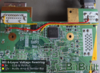
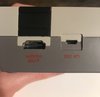
2. Where could I find guides for wiring it up to my Wii? Side note: mine is a modified version with bq and pic removed. Does that change anything?

3. How much voltage does it need? Will using the PMS eradicate the need to use an external power supply? The original Wii Micro did, but Nold only used custom regulators and not an RVL PMS (I'd really like to avoid an external power supply if possible).

4. Assuming it doesn't need the power supply, could I use any USB cable type to power it? I wanted to use Micro USB, as that's the thing used in the official Nintendo Classic Editions. Would any power board with a built-in port work (such as this cheap one I found on Amazon)?
IMG-3756.jpg

5. Finally, would it be possible to connect the USB ports built into the Wii motherboard to that same Micro USB port used for power and be able to use that to access the internal USB drive, much like the PMS PD?

Sorry, I know that's a lot for one post :blush: but I want to make sure I'm covering all my bases.
 

CrazyGadget

Crazy Helpful, CrazyGadget
.
Joined
Jun 6, 2020
Messages
618
Likes
905
Location
Downing's Closet
Portables
???
So you bought a PMS1 without knowing what it was and without knowing what it looks like... for a non-portable? Weird, but I suppose you can roll with it given the info you provided.
  1. The PMS is an all-encompassing power management system (hence the name) for the Wii. It handles battery management, as well as power regulation to provide 1v, 1v15, 1v8, 3v3 and 5v to the Wii / other peripherals in a portable. It looks like this:
    Wii Power Management System is now Open Source! – GmanModz
  2. Discontinued BitBuilt Custom PCB
    Without the PIC and BQ, it essentially is just a PSU now - a set of regulators with no battery management. I'm going to take a wild guess you bought this off of Jeffery lol.. in which case, look here: Pms to Psu Mod
  3. When you say external power supply, what do you mean? A power supply is anything from the Wii'd OEM power brick to a 5V wall wart.
  4. As long as your wall wart can supply 5v with at least 2A, it will work.
  5. You would need a USB MUX if you want an internal USB drive.
 
Joined
Nov 13, 2022
Messages
180
Likes
53
So, while I wait for the PMS 1 to arrive, I figured I might as well test my trim with the PMS lite that I have on hand. Is the process of wiring it up to the Wii Micro trim the same as for a Wii portable trim? What should I use to power this test run? The batteries I bought for my portable or the the PMS PD hooked up to wall power?
 

CrazyGadget

Crazy Helpful, CrazyGadget
.
Joined
Jun 6, 2020
Messages
618
Likes
905
Location
Downing's Closet
Portables
???
The PMS (all) requires batteries to operate, so you can't run it just off of wall power to the PD board. Depending on what revision PMS Lite you have, it may or may not work on 6 layer boards. In terms of wiring, you just need 1v, 1v15, and 3v3 to the Wii, and 5V to whatever peripherals require it. I would recommend referencing the 6 Layer Expansion to the Trimming Guide, as well as the Noldendo Miicro thread; they are both invaluable assets for 6 layer builds.
 
Joined
Nov 13, 2022
Messages
180
Likes
53
Sorry for the gap between uploads, everyone. But I've got good news! Just ordered a PSU Plus from CrazyGadget and it'll arrive on Friday (hopefully going to try and wire it up this weekend). Now that I've got power figured out though, I have a question regarding video. Since this project is a Nintendo Classic Edition, I wanted incorporate a full size HDMI out port. I did some research and stumbled across the site, Electron Shepherd (I assume some of you have heard about it). Either way, they have several good options for my HDMI needs, and I've settled on this board. Can anyone confirm whether this will be compatible with the Wii Micro trim?
 

CrazyGadget

Crazy Helpful, CrazyGadget
.
Joined
Jun 6, 2020
Messages
618
Likes
905
Location
Downing's Closet
Portables
???
That will work, but if you are willing to spend a little more, the AVE-HDMI will give you even better quality and, with it now being a flex PCB, is even easier to install than the Analog2HDMI IMO.
 
Joined
Nov 13, 2022
Messages
180
Likes
53
That will work, but if you are willing to spend a little more, the AVE-HDMI will give you even better quality and, with it now being a flex PCB, is even easier to install than the Analog2HDMI IMO.
On a scale of 1 to 10 (1 being identical to the AnalogToHdmi), how much better would you say the video quality is?
 
Joined
Nov 13, 2022
Messages
180
Likes
53
Ah, I see. Oh well, $70 for a 50% better screen isn’t really in the budget right now. Maybe I’ll make a version 2 at some point that’s even smaller, incorporates an internal USB drive, and uses the 6.53 out of 10 better HDMI port XD.
 
Joined
Nov 13, 2022
Messages
180
Likes
53
Quick question: I'm currently searching for a USB C PD board on Amazon. What aspects should I be considering when looking for one to buy? I know the Wii takes in 12 volts, but what else matters? Static power consumption? Input protocol? Whether it's a "trigger board" or not?
 

Stitches

2 and a Half Dollarydoos
Staff member
.
.
Joined
Feb 5, 2017
Messages
3,864
Likes
3,034
Location
Banana Bender Land, Australia
Portables
6
Quick question: I'm currently searching for a USB C PD board on Amazon. What aspects should I be considering when looking for one to buy? I know the Wii takes in 12 volts, but what else matters? Static power consumption? Input protocol? Whether it's a "trigger board" or not?
The main thing is that everything supports the required current of whatever voltage you're using. If you're going to use 12v over USB-C, make sure your PD module, the power supply, and the cable (some are cheap shit) all support the full 1.5amps of 12v. 6 layers be thirsty lads
 
Joined
Nov 13, 2022
Messages
180
Likes
53
The main thing is that everything supports the required current of whatever voltage you're using. If you're going to use 12v over USB-C, make sure your PD module, the power supply, and the cable (some are cheap shit) all support the full 1.5amps of 12v. 6 layers be thirsty lads
So as long as it supports above 1.5 amps, it’ll be fine?
 

Stitches

2 and a Half Dollarydoos
Staff member
.
.
Joined
Feb 5, 2017
Messages
3,864
Likes
3,034
Location
Banana Bender Land, Australia
Portables
6
So as long as it supports above 1.5 amps, it’ll be fine?
1.5A stable is the goal, yeah. You can probably get away with 1A since the disc drive isn't present, but I don't know whether all 4 controllers vibrating at the same time would push the total system draw over 1A. For safety I'd go with 1.5A. That way there's no risk of browning out
 
Joined
Nov 13, 2022
Messages
180
Likes
53
Alright! Thanks to CrazyGadget, I have finally managed to snag myself a PSU Plus and am ready to begin soldering! Before I begin though, I have a few questions regarding rewiring the voltages. I've done my best to decipher the correct locations of as many of them as I could, but there are a few that have stumped me (I feel bad asking for help on something as simple as this but I'm not super experienced reading that kind of diagram). I understand the 12v sensor bar and the 5v USB, but I need help with the rest:

Does "1.8v bridge" literally mean I just have to bridge two 1.8 volt spots?

For the life of me I can't find out where the audio amp is even after inspecting the trimming guides (but I do know I just need to wire up 12v to it)

When it says I need 5v to the AV port, does that just mean I wire up a 5v component to the 5v pin on the video port?

I have no clue what ofc 3v3, 1v15 (I assume he meant to write something different, as max volt on Wii is 12v, right?) and 1v means. However, I suspect it has something to do with that mysterious wire trailing off to the front of his Wii board in the photo on the Wii Micro guide.
1698363764625.png

Any help would be greatly appreciated! I can't wait to continue working on this project.
 

Stitches

2 and a Half Dollarydoos
Staff member
.
.
Joined
Feb 5, 2017
Messages
3,864
Likes
3,034
Location
Banana Bender Land, Australia
Portables
6
Does "1.8v bridge" literally mean I just have to bridge two 1.8 volt spots?
Yep. The OM6 trim severs an internal 1.8v trace, so you need to run a wire between the two 1.8v locations shown in the 6 layer trimming expansion.

For the life of me I can't find out where the audio amp is even after inspecting the trimming guides (but I do know I just need to wire up 12v to it)
The audio pre-amp is U7. It's the 8 legged IC below the AVE.

When it says I need 5v to the AV port, does that just mean I wire up a 5v component to the 5v pin on the video port?
Yes, you need to run a 5v supply wire to the AV port. The easiest way to do that is to run a wire from the USB port's 5v pins to the AV port's 5v pin.
I have no clue what ofc 3v3, 1v15 (I assume he meant to write something different, as max volt on Wii is 12v, right?) and 1v means. However, I suspect it has something to do with that mysterious wire trailing off to the front of his Wii board in the photo on the Wii Micro guide.
View attachment 30445
Silkscreen designators are a little different to text writeups. Voltage designators in silkscreen are printed as: (whole number) v (decimals). So 3v3 = 3.3v, 1v15 = 1.15v, and so on. As for the wires, ignore them. Those pictures were taken from a Wii micro where 12v isn't used, so 5v is fed into the 12v lines to run the pre-amp and sensor bar. If you wire yours like that, you'll dump 12v into the 5v line. All you have to do since you plan to use 12v, is run a wire from the AV port's 5v pin directly to the USB port's 5v pin, and then supply 12v to the pre-amp directly, or to TP213. That'll keep the lines separate, and it all *should* just work.
 
Top