
You don't need to sever the trace if the board is already trimmed.
Worklog Nintendo Wii Classic Edition
- Thread starter Lemoncake
- Start date
- Joined
- Nov 13, 2022
- Messages
- 241
- Likes
- 109
U10 has been relocated successfully! This was a super momentous thing for me because the first time I ever asked for help on BitBuilt (almost a year ago at this point) was for a botched U10 relocation on my first attempt at a portable. I never would’ve been able to get this far without everyone here’s advice and support. Thank you all.
If you have any thinner wire, I'd use that for U10. Thick wires can be difficult to solder to vias, and have caused breakages in the pastU10 has been relocated successfully! This was a super momentous thing for me because the first time I ever asked for help on BitBuilt (almost a year ago at this point) was for a botched U10 relocation on my first attempt at a portable. I never would’ve been able to get this far without everyone here’s advice and support. Thank you all.View attachment 30527
Magnet wire will do, yeah. The U10 output is just a reference signal and barely carries any current, so magnet wire is fine and is actually recommended. Unsure about the power draw, but it should be a good signThe only thinner wire I have is the magnet wire. Would that work? Also, second test update: we still don’t have any booting, but the Wii is now drawing 0.589 amps instead of the previous 0.289. Is this telling in any way?
- Joined
- Nov 13, 2022
- Messages
- 241
- Likes
- 109
3rd test results: First off, I removed the controller ports I had previously attached to the Wii just to limit the number of potential problem causers (I don't trust my soldering job on them :/ ). I fixed a few of my solder joints that were bridging with some small vias, as well as replacing the U10 wire with magnet wire instead per Stitches recommendations. It still isn't booting, but we're making progress. The Wii is now drawing around 0.7 amps (much closer to CrazyGadget's original prediction) and the fan, which previously did nothing despite being plugged into the motherboard, is now spinning at full speed. The troubleshooting process continues, but at least we're heading in the right direction.
Try exposing some more wire and fanning it out a bit so the the aligator clips can grip the wire with both horizontal rows of teeth
It helps to double check your resistances on the voltage lines once everything is hooked up. You're only really looking for dead shorts that shouldn't be there. Also be sure to check all of your voltages, both at the PSU side and the Wii side, while it's powered on. Perhaps something is up with the power. Do you have at least 2 ground wires between the PSU and the Wii? 6-layers *need* at least 2.
- Joined
- Nov 13, 2022
- Messages
- 241
- Likes
- 109
I do have 2 GND wires between the PMS and the Wii (the second one is going to the GND pin on the AV port). Since there’s space for a 3rd, should I add one? I’ll check the voltages ASAP. Is there a guide I can consult that’ll tell me what voltages to look for?
You just want to make sure you're getting the proper voltages from the PSU and that they are the same on the Wii (wires can add a slight voltage drop, but your lines are pretty short so I don't think that would be a problem). If any of the main voltage lines are shorted, the regulators should not output, so you would read 0V.
- Joined
- Nov 13, 2022
- Messages
- 241
- Likes
- 109
I checked the voltages and here are the results. There don't appear to be any shorts from the PMS to the Wii because when I pressed the one probe of the multimeter against the VIN pad and the other against a voltage pad, nothing read 0v (except from the VIN pad to the VIN pad but I expected that). I got mostly the same results from both the spot on the PMS and that same voltage location on the Wii (CrazyGadget mentioned voltage drops, but weirdly enough I moslty only experienced raises: 1.15v from the PMS gives me 9.99 but on the Wii it gives me 10.01 and from 5v I'm getting 6.51 and 6.61 respectively). The only voltage drop was on 1.8v which gives me 11.14 on the PSU but only 9.52 on the Wii. Also, none of the readings I got were anywhere close to their descriptions: the 1v pad gave me 10.06, 3.3v gave 8.03, 1.15 gave me 9.99, 5v gave me 6.51 and GND gave me 11.14 (same as the 1.8v pad on the PSU). For reference, my multimeter is set to Voltage for DC current and is turned to the 20 setting. Do these results tell you anything?
You're reading all of those voltages in reference to 12V, that's why your readings are wack. Those are the differences between the output voltages and 12V. You want to read all of the voltages in reference to ground: black probe goes to ground, red goes to the voltage you want to read.
- Joined
- Nov 13, 2022
- Messages
- 241
- Likes
- 109
Gotcha  . You learn something new every day , I guess! I redid all the readings and it makes much more sense now. All the voltages are slightly lower than described now: 1v is 0.96, 1.15v is 1.11, 3v3 is 3.2, 5v is 4.78, VIN (12v) is 11.12 and 1.8v is 1.71 (all going from the GND on the PMS to the pads on the PMS). In terms of voltage drops, there isn't really anything greater than 0.01v from the PMS to the Wii. These numbers make much more sense now, but do they all check out? And in that case, what could still be stopping this guy from booting?
. You learn something new every day , I guess! I redid all the readings and it makes much more sense now. All the voltages are slightly lower than described now: 1v is 0.96, 1.15v is 1.11, 3v3 is 3.2, 5v is 4.78, VIN (12v) is 11.12 and 1.8v is 1.71 (all going from the GND on the PMS to the pads on the PMS). In terms of voltage drops, there isn't really anything greater than 0.01v from the PMS to the Wii. These numbers make much more sense now, but do they all check out? And in that case, what could still be stopping this guy from booting?- Joined
- Nov 13, 2022
- Messages
- 241
- Likes
- 109
Okay. So I did a bit of research into some of the other BitBuilt forums regarding troubleshooting Noldendo Micros and found something that helped others when nothing else worked. They simply didn't have enough power going to their trims. Here, AydenRad switched his power supply from 12v 2amps to 3amps. Would attempting something like that with my board be a good idea?
Unknown. Your desktop supply has a 5A current max, so in theory it should be the best testing option if it's working properly. You could try a conventional 12v 3A supply just to cross it off the list. It certainly wouldn't hurt anything
- Joined
- Nov 13, 2022
- Messages
- 241
- Likes
- 109
Could I wire up the Wii’s original power supply to accomplish that? It says it’s rated for 12v 3.7amps.Unknown. Your desktop supply has a 5A current max, so in theory it should be the best testing option if it's working properly. You could try a conventional 12v 3A supply just to cross it off the list. It certainly wouldn't hurt anything
Yessir, it's what it was designed for after allCould I wire up the Wii’s original power supply to accomplish that? It says it’s rated for 12v 3.7amps.
- Joined
- Nov 13, 2022
- Messages
- 241
- Likes
- 109
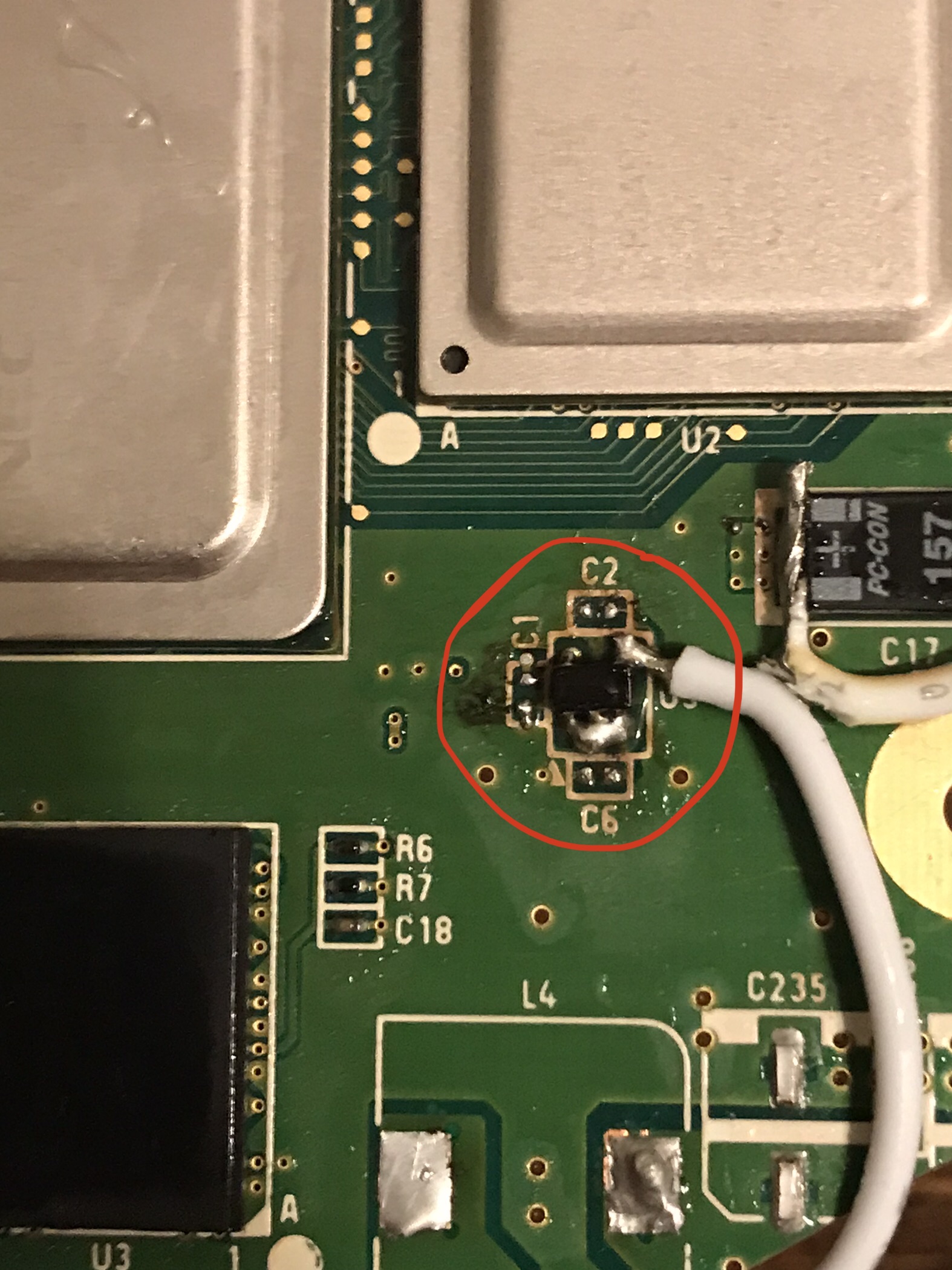
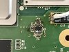
So I tried the Wii’s original power supply, and still no luck. The fan powers on, the chips get warm, but still no boot. I attached some photos of my board/soldering job below. If anyone spots some mistake I’ve made, please do not hesitate to let me know. I’ll keep brainstorming solutions on my end. (A note on one of the photos: when I tried to wire up a 1.8v line to one of the components, I accidentally removed one of the small capacitors. After consulting Shanks guide I managed to replace it with another one of the same value, but let me know if it seems to be a shoddy relocation. Here’s a photo.)
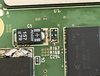
Here are the ones of the rest of the board:
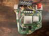
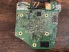
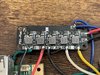
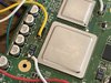
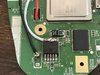
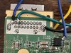
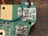

Thanks in advance for any observations. Let’s get this thing working!
Here are the ones of the rest of the board:
Thanks in advance for any observations. Let’s get this thing working!
Low, but not zero. If you have any compressed air, a good long blast around the dies and RAM is worth a try