What's new

PS2 Ultra Slim

Joined
Jun 9, 2024
Messages
13
Likes
7
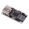
I modified a v1.2 case to accomodate a PD trigger board to use instead of a regular DC jack. @Wesk might want to add this somewere in one of his posts
This is for a HW-398 trigger board.
1718612220047.png

Make sure your trigger/decoy board is set to 9V
There are no guarantees that powering your console this way will not fry it. PS2 79XXX is rated for 8.5V input so do this at your own risk.


The print for me was a snug fit and I think you can just push the board in without a retainer but you risk displacing it. You need to push the buisiness end into the hole first and then push the rest of the board flat onto the platform.
You will need to use 2 M3x6 screws to mount a retainer. The screw holes are small enough for the screws to self tap. Make sure to not overtighten them else the standoffs will break off.

I am including a test part so you do not need to print the whole half to test fit your board.

CAD files are included so you can modify the design if necessary. The TestPart.step is also included and can be used to modify the other variations of the top shell.
 

Attachments

Joined
Apr 6, 2024
Messages
4
Likes
0
@TheFizz Interesting - I'm facing the exact same issue with the ethernet port, but thought it may be related to my wiring or printing being slightly out of alignment...
 
Joined
Jun 9, 2024
Messages
13
Likes
7
@TheFizz Interesting - I'm facing the exact same issue with the ethernet port, but thought it may be related to my wiring or printing being slightly out of alignment...
I looked at my original shell and it seems that the inner lip above the ethernet port is slightly higher. I might fix it in CAD and reprint but the power outages are too frequent during daytime and the print will not complete so gotta wait till night.

Also, the post about my power delivery modification with files is on moderation now so it should appear soon.
 

Wesk

Undervolting....
Staff member
.
.
Joined
Jul 12, 2017
Messages
929
Likes
2,428
Location
Queensland, Australia
I looked at my original shell and it seems that the inner lip above the ethernet port is slightly higher. I might fix it in CAD and reprint but the power outages are too frequent during daytime and the print will not complete so gotta wait till night.

Also, the post about my power delivery modification with files is on moderation now so it should appear soon.
The ethernet inner lip was modified to avoid clearance issues that some were having. I'm not sure why you're having fitment issues as the changes from V1.1 were mostly minimal. Perhaps try V1.1 and see if fitment is better.
 
Joined
Apr 6, 2024
Messages
4
Likes
0
The ethernet inner lip was modified to avoid clearance issues that some were having. I'm not sure why you're having fitment issues as the changes from V1.1 were mostly minimal. Perhaps try V1.1 and see if fitment is better.
1.1 fitted better for me, I just wanted to upgrade to A2HDMI...
 
Joined
Jun 9, 2024
Messages
13
Likes
7
Perhaps try V1.1 and see if fitment is better
I finally was able to test this and yeah, overall it was easier to fit the board inside the v1.1 case but it is still wasn't perfect. I guess the main reason why both I and @bbsan2k found it better is beacause the rear panel is thinner compared to v1.2 and, therefore, it feels easier to put everything together. The rear just deflects easier. But in fact, the ethernet portion of it still gets in the way. I will try to fix this for myself somehow once I have at least 3 hrs of uninterrupted electricity.

P.S. This is not a complaint but a feedback. I can't even imagine how hard it is to produce a good 3D scan, let alone make an accurate printable model based on it
 

Wesk

Undervolting....
Staff member
.
.
Joined
Jul 12, 2017
Messages
929
Likes
2,428
Location
Queensland, Australia
I finally was able to test this and yeah, overall it was easier to fit the board inside the v1.1 case but it is still wasn't perfect. I guess the main reason why both I and @bbsan2k found it better is beacause the rear panel is thinner compared to v1.2 and, therefore, it feels easier to put everything together. The rear just deflects easier. But in fact, the ethernet portion of it still gets in the way. I will try to fix this for myself somehow once I have at least 3 hrs of uninterrupted electricity.

P.S. This is not a complaint but a feedback. I can't even imagine how hard it is to produce a good 3D scan, let alone make an accurate printable model based on it
So would you say the fitment near the rear of the shell is the problem?
 
Joined
Jun 9, 2024
Messages
13
Likes
7
So would you say the fitment near the rear of the shell is the problem?
Yeah, it looks like the issue is around the ethernet port on the top half. Both v1.1 and v1.2 bottom halves were a tight fit but still ok. v1.1 and v1.2 top halves both resist(?) around the ethernet. Here's how v1.1 looks like. I think you can see where the problem is
1718839295055.png
In a v1.1, this portion sits against the ethernet port and won't let the case to sit properly
1718839716513.png

In v1.2 this lip seems to be too low, which also prevents the shell from closing properly. But I am not sure about that.
1718839842889.png

I think that the boards we have and the board that was 3D scanned might be different revision. While the model numbers are all good, Sony might have minor differences between board revisions. This is just a wild guess though.


Printing the updated files now, will tell you how it goes. Thank you.
 
Joined
Jun 9, 2024
Messages
13
Likes
7
Can you guys try the attached files out and let me know how fitment goes
I printed this version and it still won't close at the rear. But this time it looks like the problem is not with the ethernet but with an optical audio port. I have another 79XXX coming my way, I will try it with all the cases I previosly printed. I think there is a decent chance there is something with my board.
 
Joined
Jun 24, 2024
Messages
4
Likes
3
Not sure if this was already covered, but some 790001 motherboards (in my case, GH-062-02) don't have the lid switch.

Serial Number: HU3775926
UPC: PD037759261
How did you cut this board, I have the same one and there is a small cap or other little electical device right in line of where you cut the USB port off on the back side. Is it ok to remove that small little piece the cut the usb part of board off?
 

Attachments

Joined
Jun 9, 2024
Messages
13
Likes
7
How did you cut this board, I have the same one and there is a small cap or other little electical device right in line of where you cut the USB port off on the back side. Is it ok to remove that small little piece the cut the usb part of board off?
In his video (link w/ timestamp), Macho Nacho desoldered this resistor(?) and I did the same and cut the USB


1719273347118.png
 
Joined
Jun 24, 2024
Messages
4
Likes
3
Finished my initial build. I do still want to add the SD card reader and the HDMI output, but that can wait a little while longer. In the meantime I did something a little different and since my board didn't have the lid switch in the back and I needed a new switch anyways, I put it up front ;) I really like this design style having the button up front, just a simple button with a 3d printed button cover. Had to make the hole a little bigger but it works really well. Would be nice if the case could be modified to allow for a specific switch to be mounted there instead of having to use hot glue though in the future.
 

Attachments

Joined
Jun 25, 2024
Messages
1
Likes
0
This is my first post and I hope I haven't missed the answer if its in here, I've read through it a few times. I am getting together all the knowledge, parts and supplies to take on this project and I think I'm just about there. The one question I have is the wire sizes needed to do this. I have seen all of Tito's videos and while he has affiliate links to some of the supplies he used, it only covers the 26/28 gauge wires used for the SD card adapter, HDMI board etc. .... but I didn't see anything about the power and ground wire gauge. I want to make sure the wire is a large enough gauge but not be as so large that its to hard to work with. Any help would be greatly appreciated.

CptJack
 
Joined
Jun 24, 2024
Messages
4
Likes
3
This is my first post and I hope I haven't missed the answer if its in here, I've read through it a few times. I am getting together all the knowledge, parts and supplies to take on this project and I think I'm just about there. The one question I have is the wire sizes needed to do this. I have seen all of Tito's videos and while he has affiliate links to some of the supplies he used, it only covers the 26/28 gauge wires used for the SD card adapter, HDMI board etc. .... but I didn't see anything about the power and ground wire gauge. I want to make sure the wire is a large enough gauge but not be as so large that its to hard to work with. Any help would be greatly appreciated.

CptJack
Pretty sure he used the same for the power, at least from the looks of it. They are very short cable runs after all.
 
Joined
Jun 27, 2024
Messages
4
Likes
5
Ps2 ultra slim elimine los conectores de network y optical y puse una entrada hdmi y un adaptador usb-c para la corriente

Ps2 ultra slim I removed the network and optical connectors and put an hdmi input and a usb-c adapter for power.

Mod Edit: English translation
 

Attachments

Last edited by a moderator:
Joined
Jun 9, 2024
Messages
13
Likes
7
Ok so I finished the build.
1719809125793.png
1719809138018.png
1719809148465.png

I made a few modifications to both the case and the motherboard itself (v.1.2). I removed the original power plug, replaced it with a 9V PD trigger board and also wired it to a separate DC output. I made modifications to the top shell to accomodate both the board and the barrel jack. And no, I didn't have to unscrew the halves after everything was assembled because I didn't install a PD board retainer, why do you ask?
1719809417010.jpeg

Since I didn't have a requred MX4SIO/Memcard switch, I adapted the bottom half to take in the one I had on hand. I also absolutely definitely did not forget to bridge/put a resistor between ACK and GND on an adapter and it predictably worked flawlessly on the first try (no, seriously, it did work. Maybe that's because samsung adapter or idk). And I put some kapton on top of the switch. It has metal housing and is slightly bigger than what Wesk suggested so I thought better safe than sorry. And yeah, I glued that in because I didn't have an opportunity to test fit the print. I also repositioned the SD card opening .5 mm lower because it seemed too high. Now it is spot on.
1719809769854.png
1719809778419.png
1719810874187.png

Next was the button. This version of the board didn't have a lid switch, so I just went to a local repair shop and asked them for a button. They gave me the button. I soldered in the button. It has become The Power Button. I also wrapped it around with kapton because of metal housing. I didn't fix it in any way but it kinda just stays there so I think I'm good. I also made the printed button a bit longer.
1719810220902.png

Finally, I put together the parts. It was an exclamation mark on everything that had led to this point. I released my finger from the trigger, and it was over. I was expecting it to not sit well as it was previously, but I made one crucial change. I removed a lip around optical audio and all of a sudden, it fit like a glove. I don't really know why this helped me while nobody else had this issue but I figured I'd just share. @Wesk might wanna look into it?
1719810777901.png
1719810807009.png

So, all in all, it was a satisfying build. Or even a journey of being able to only print one piece a day and trying to adjust the design to fit my board. Apart from minor printing artifacts, I'd say it came out pretty good.

Oh, about that 9V DC out. I have a cheapo analogue automotive display (you know, the one for a rear camera). I use it as a portable display to be able to play when there is no power. It requires 12V and while the console needs 9V, I cannot just stick both into my powerbank. The plan was to have the console output 9V directly from PD board and then integrate a boost converter into the cable to boost 9V to 12V. Surprisingly enough, the screen actually works with only 9V power. And it works really good without artifacts, with good brightness and contrast and all. I'm guessing it has some conversion circuit inside of it but I am not sure.
1719811442894.png

So there's that.

P.S. If somebody knows a decent screen with a driver that I could buy on aliexpress and that would be easy to solder in please let me know. I want to convert this thing to become fully autonomous, much like PSOne with LCD attachment but also with internal battery. I know I will not be able to make it fully portable (and I don't really want to), but I'd like it to be sorta all-in-one.
 
Joined
Jul 24, 2024
Messages
2
Likes
0
Hi, I've ordered a 79003 model after searching ebay for a few weeks, but after ordering I saw a comment on macho nachos youtube video saying 79003 isn't compatible with the case as the eject button sticks out preventing it from fitting in the case. Has anyone used a 79003 model with any success and can confirm if this is true or not? Gonna hold off on getting a case from pcb way for now. Appreciate any feedback, thanks!
 
Top