
This is what I've been thinking for a while. If both NANDs and 3 daughterboards are relocated (and SMC disabled), it seems like just a matter of time until someone trims up to those 2 inductors next to the RAM (or around there). Of course this will be cutting off 2 of the regulators but that isn't an issue if using custom ones like the board that Yveltal designed, and if the SMC and RTC can get taken care of. I also wonder if the availability of those custom, beefy regulators have changed ever since the pandemic. Huge props to Yveltal, Nold, leprechaun, and others for their effort!This is really awesome. If the flash can be removed and replaced with an SD card soldered to vias under the SOC, the wireless modules could be relocated, disc drive can be relocated with 4 wires, and custom regulators can be used, that really narrows things down. We could be pretty close to straight up cutting off half the board. Is there anything else other than the controller chip on the front of the board?
Worklog Wii U R&D Thread (WURD)
- Thread starter Shank
- Start date
RedNAND vWii doesn't work, good to know. I was panicking hard a few weeks ago when I tried to boot into redNAND vWii and it kept death screening. I thought I fucked the setup and it got corrupted............ well that's one less thing to worry about.ShinyQuagsire has been making huge headway with the softmodding side of things, which has big implications for the hardware:
- Thanks to his Wii U modchip (which uses the de_Fuse exploit he discovered), the disc drive has been entirely patched out and is no longer required for boot.
- ShinyQuagsire's modchip also lets you set up redNAND, which redirects NAND calls to an SD card. However, vWii doesn't work with redNAND, and no one has combined redNAND for Wii U mode and SNEEK for vWii mode. So relocating both memories by cutting around them as described earlier in the thread is still the best approach imo.
- The SMC and RTC both need to be relocated since the Wii U talks to them at boot. ShinyQuagsire thinks they could eventually be replaced with a microcontroller but relocating them will be simpler for now.
- As it turns out, there are indeed some "gotchas" with the SMC. ShinyQuagsire used my board scans to trace out the SMC's 1V sense line and disabled it when he was running undervolting/glitching tests during de_Fuse development. We'll have to do something similar when using custom regs.
Big ups to @Crazzyleprechaun for inspiring me to get back in the Wii U zone!
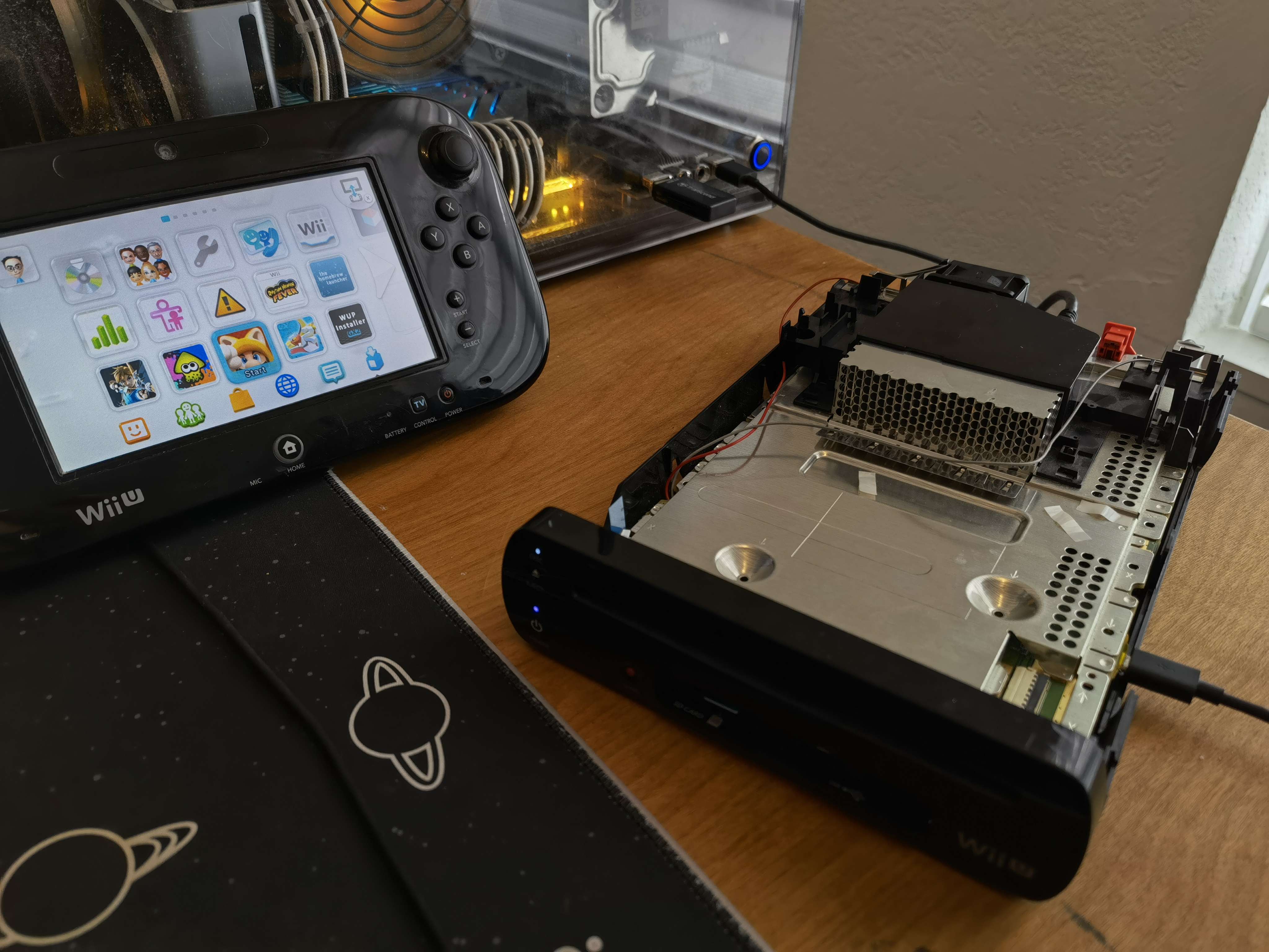
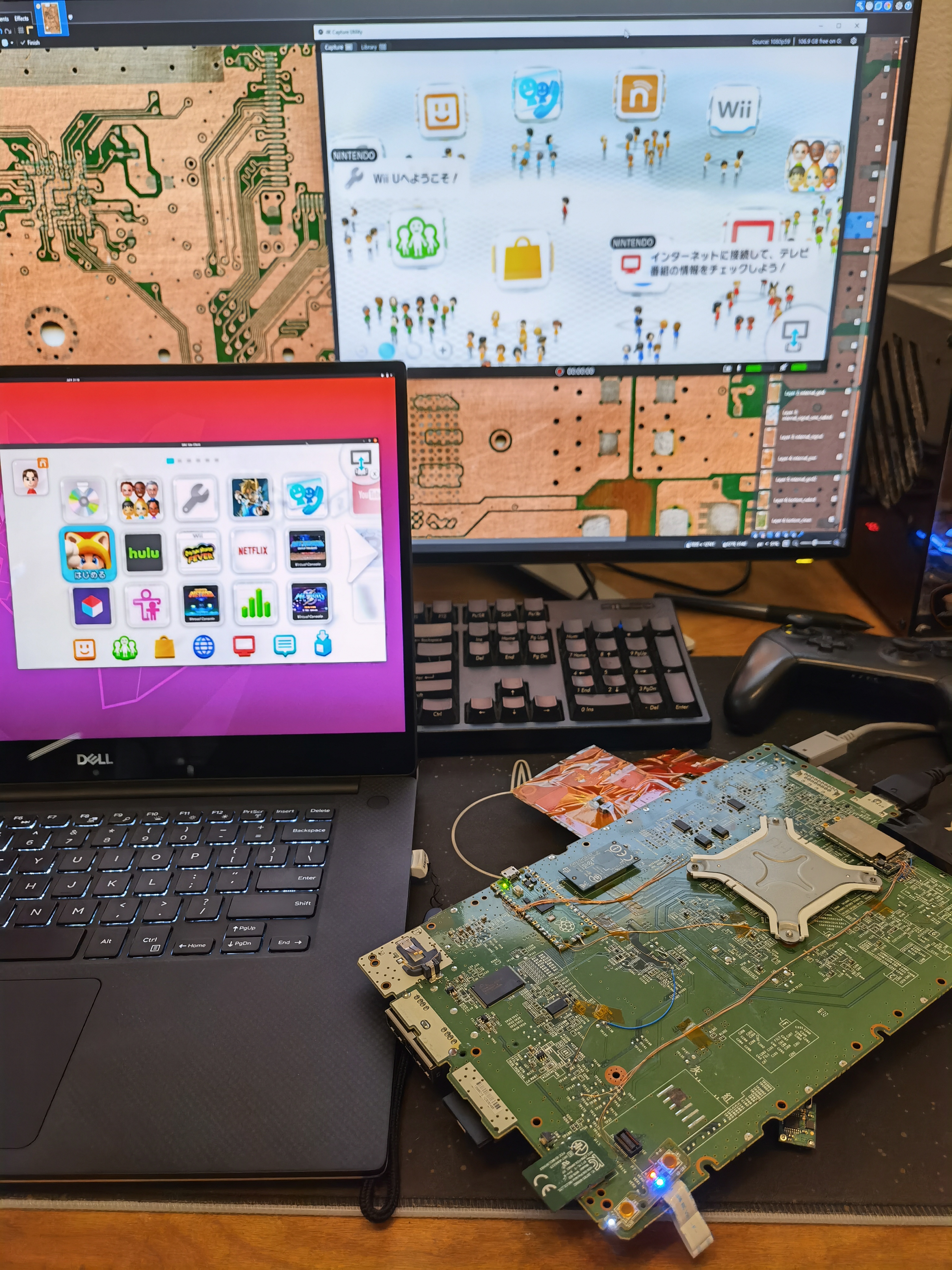
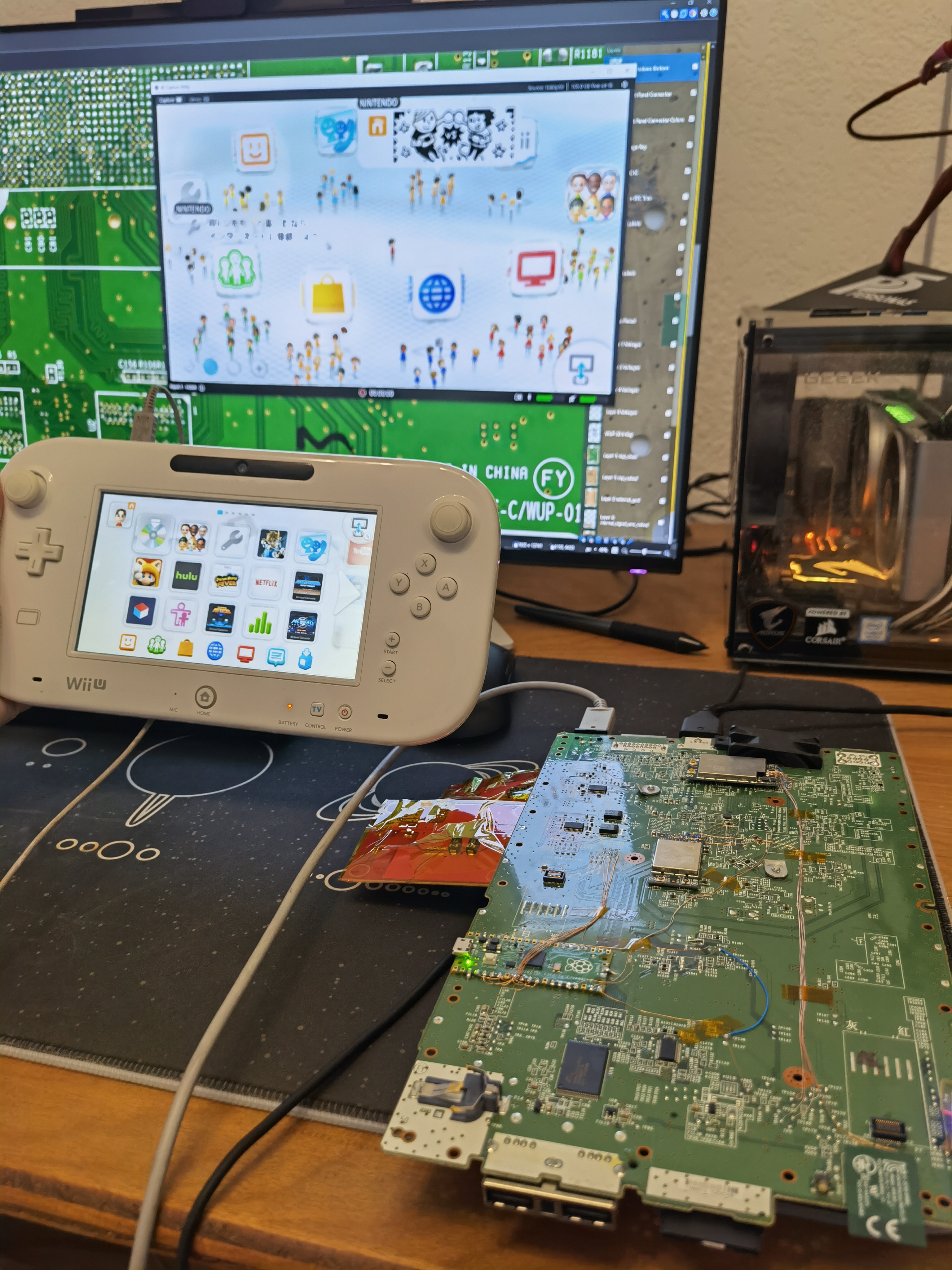
I de_Fused a WUP-01 and set it to autoboot into Aroma. This is currently the best softmod setup for a Wii U in my opinion. By installing Tiramisu, then Aroma, and configuring minute to autoboot into IOSU, you get a totally seamless experience with no disc drive. The only hardware requirements are:
I also took some rough current measurements for the rails we didn't have conclusive data for:
1V: 13A idling in the menu, 14-15A in Breath of the Wild
1.25V: ~200mA
The 1V power consumption is disappointing to say the least. The WUP-50 motherboard Drew sent me has an SMC issue and is unusable, so I have two more WUP-50s coming in the mail. I'll measure their 1V rail consumption ASAP to see if it's any lower.
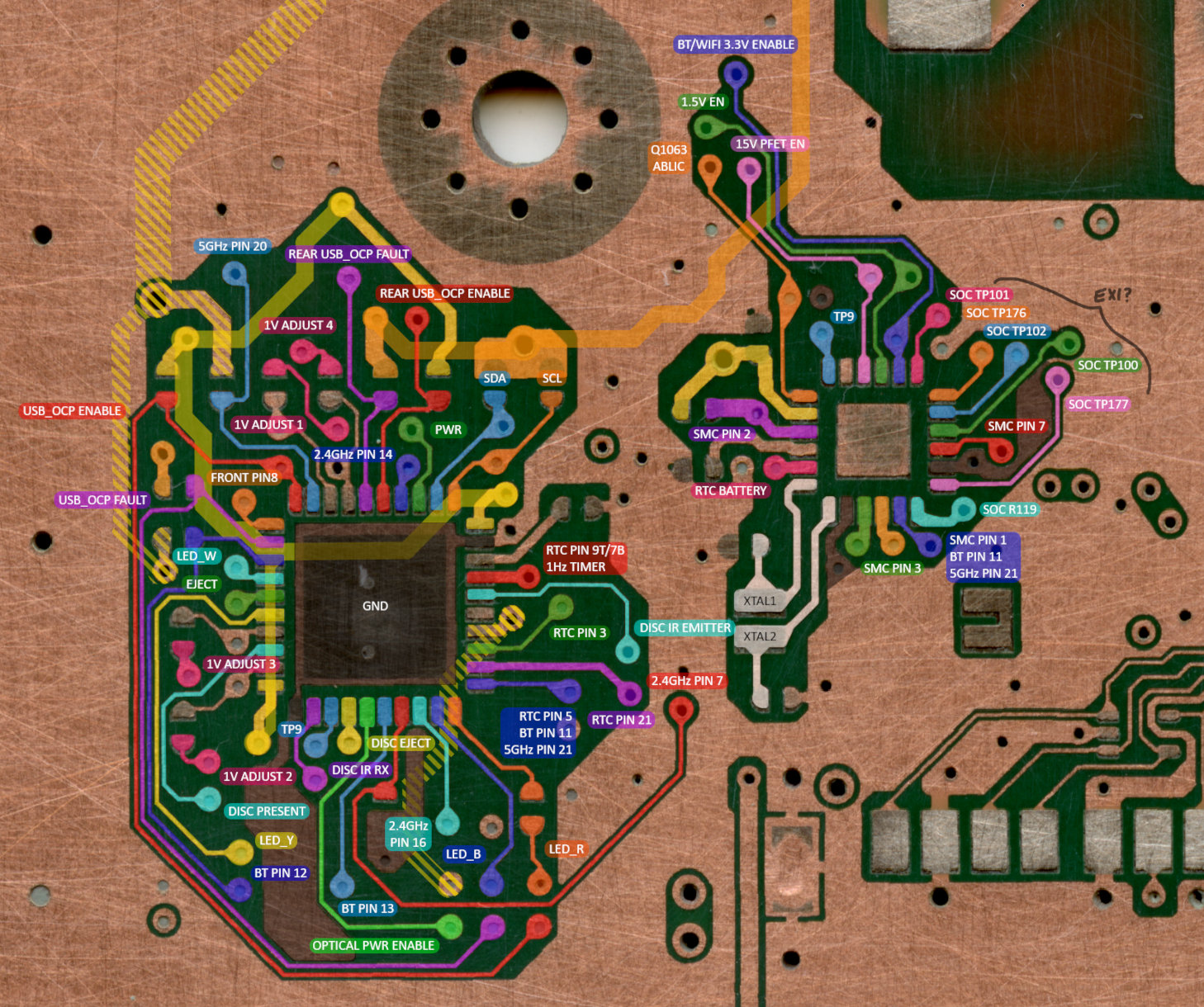
Finally, I'm resuming work on the Wii U compendium. I'm focusing on the SMC since that's the next major thing to relocate. It monitors just about every subsystem on the mobo, but with some clever reverse engineering we can figure out what each pin does and minimize the required wiring.
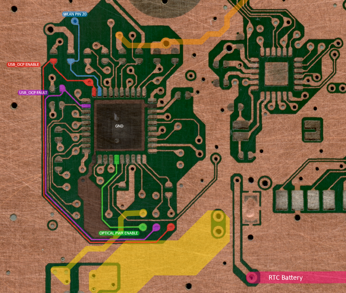
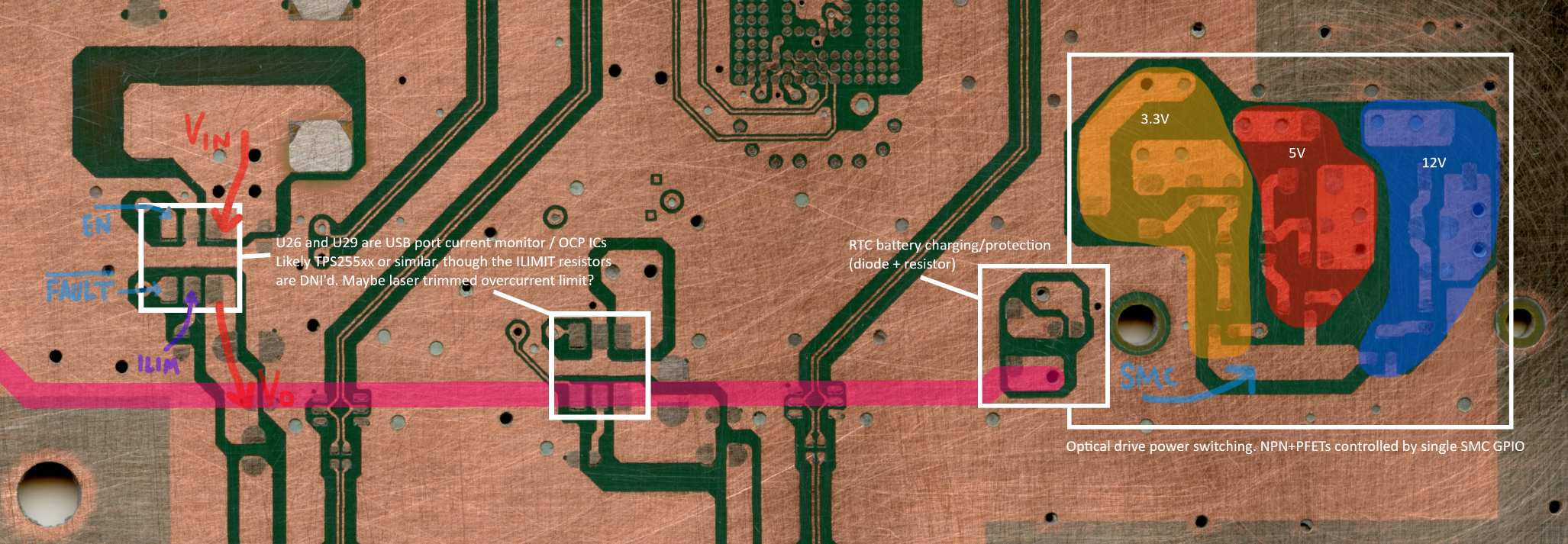
For instance, the front USB ports each have an overcurrent monitor IC. These have shared enable and fault pins connected to the SMC. After some research it's clear that the shared fault pins are open drain/active low, so as long as we preserve the pullup resistor near the SMC, we can leave that trace disconnected!
Doing things this way may be slow, but it pays off, because in the end we'll have a decent understanding of all the ICs and subsystems on the mobo. That's important for troubleshooting and making sure trimming goes smoothly.
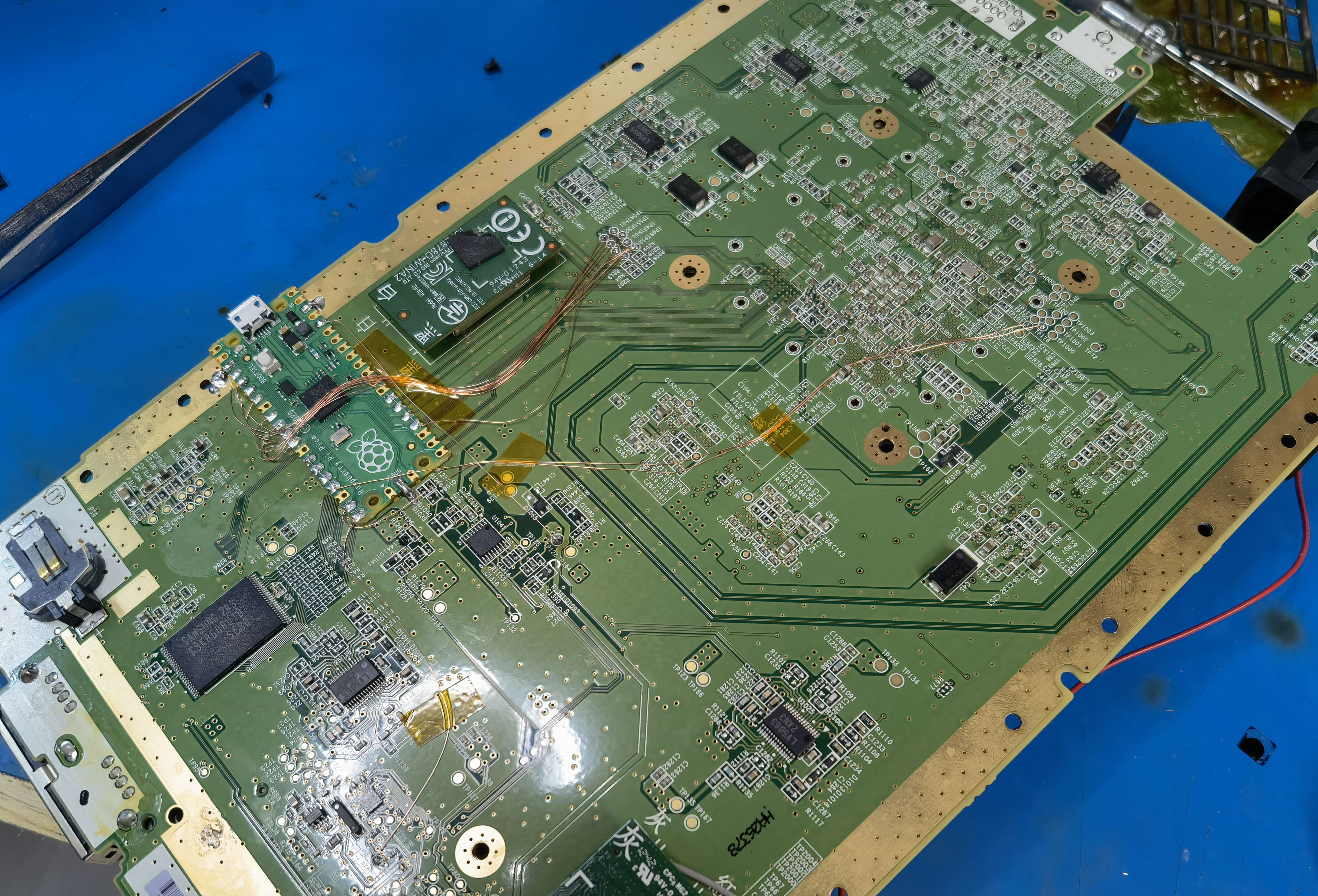
I de_Fused a WUP-01 and set it to autoboot into Aroma. This is currently the best softmod setup for a Wii U in my opinion. By installing Tiramisu, then Aroma, and configuring minute to autoboot into IOSU, you get a totally seamless experience with no disc drive. The only hardware requirements are:
- de_Fuse hardmod, which uses a Raspberry Pi Pico or other RP2040 board
- a non-SDHC SD card for loading minute (<2GB). I'm using a no-name 512MB one. You need an SD card for Aroma anyway so this isn't a big deal.
I also took some rough current measurements for the rails we didn't have conclusive data for:
1V: 13A idling in the menu, 14-15A in Breath of the Wild
1.25V: ~200mA
The 1V power consumption is disappointing to say the least. The WUP-50 motherboard Drew sent me has an SMC issue and is unusable, so I have two more WUP-50s coming in the mail. I'll measure their 1V rail consumption ASAP to see if it's any lower.
Finally, I'm resuming work on the Wii U compendium. I'm focusing on the SMC since that's the next major thing to relocate. It monitors just about every subsystem on the mobo, but with some clever reverse engineering we can figure out what each pin does and minimize the required wiring.
For instance, the front USB ports each have an overcurrent monitor IC. These have shared enable and fault pins connected to the SMC. After some research it's clear that the shared fault pins are open drain/active low, so as long as we preserve the pullup resistor near the SMC, we can leave that trace disconnected!
Doing things this way may be slow, but it pays off, because in the end we'll have a decent understanding of all the ICs and subsystems on the mobo. That's important for troubleshooting and making sure trimming goes smoothly.
Translation: "I can't put into words how grateful I am."Не могу передать моей благодарности словами
@Lilikimilk BitBuilt это преимущественно англоязычный форум, пожалуйста, пишите на английском (или используйте DeepL, это действительно хороший сайт-переводчик).
BitBuilt is a primarily English speaking forum, please write in English (or use DeepL, it's a really good translator website.)

I've made some major progress! Time for an info dump.
Big news! WUP-50s only draw ~9A on the 1V line. This is 5 to 6 amps less than a WUP-01! So it appears there was a dieshrink (or some other silicon optimization) on the later revs with smaller MCMs.
1A @ 1V = 1W, so this is a ~6W power save at the mobo level (and closer to 7W if you take into account regulator losses.)
But the harsh reality is that WUP-50s are very uncommon. For every one WUP-50 on eBay, there are about a hundred WUP-01s. Focusing solely on the WUP-50 doesn't align with the goal of democratizing Wii U portablizing.
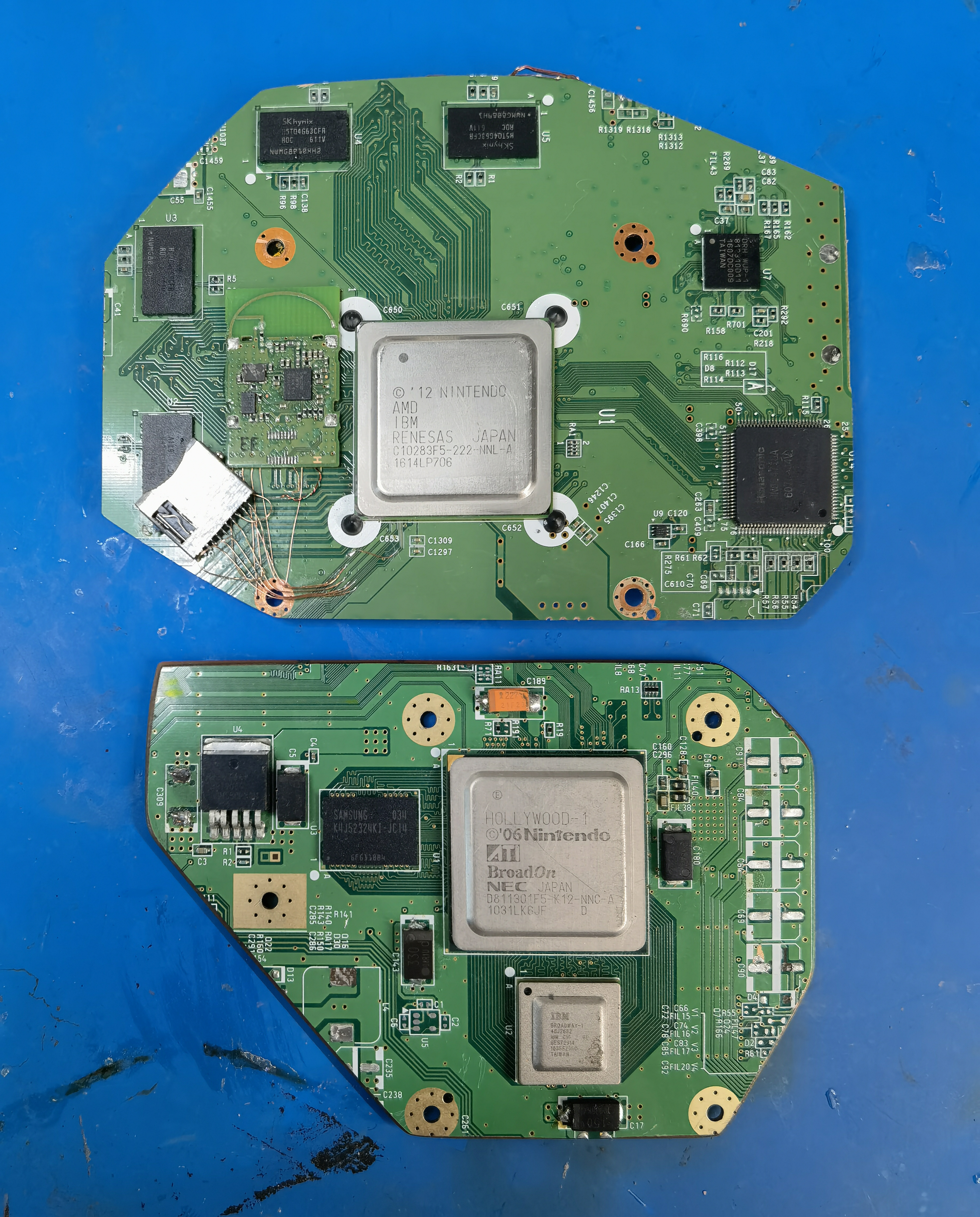
Luckily, the WUP-50 is very similar to the WUP-01, besides the routing changes around the SOC and RAM. SMC/RTC/eMMC/NAND/wireless routing is almost 1:1, and crucially, most test pads are still present. So the relocations and trims for WUP-01 and WUP-50 will be very similar, and the majority of my WUP-01 compendium work applies directly to the WUP-50.
Speaking of compendium work, I've fully pinoutted the SMC, RTC, and ABLIC.
Here's the gist of this RE work:
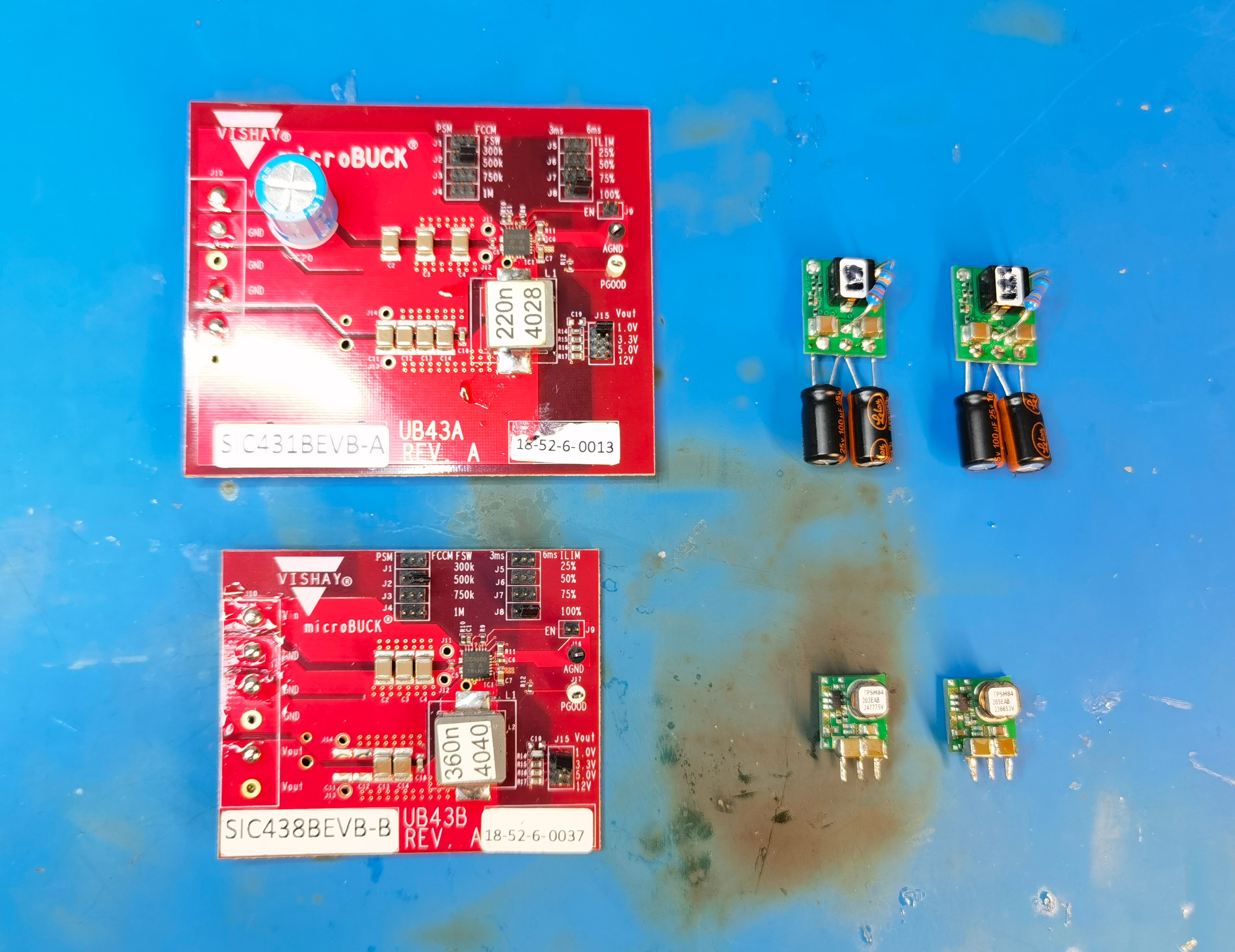
In keeping with the plan I outlined last year, I decided to tackle custom regs next. @Redherring32 turned me on to some sweet Vishay regulators (SiC43X family) which are way cheaper and simpler than the goofy TI regs on my old reg board. In the interest of time, I picked up some evaluation boards for two of them along with some smaller regs for the low-current rails.
Full disclosure, I did have to swap inductors and feedback resistors on the EVBs to get the right voltages/currents. Using maximum thickness wire (~12AWG), since in my experience the Wii U really doesn't like voltage droop.
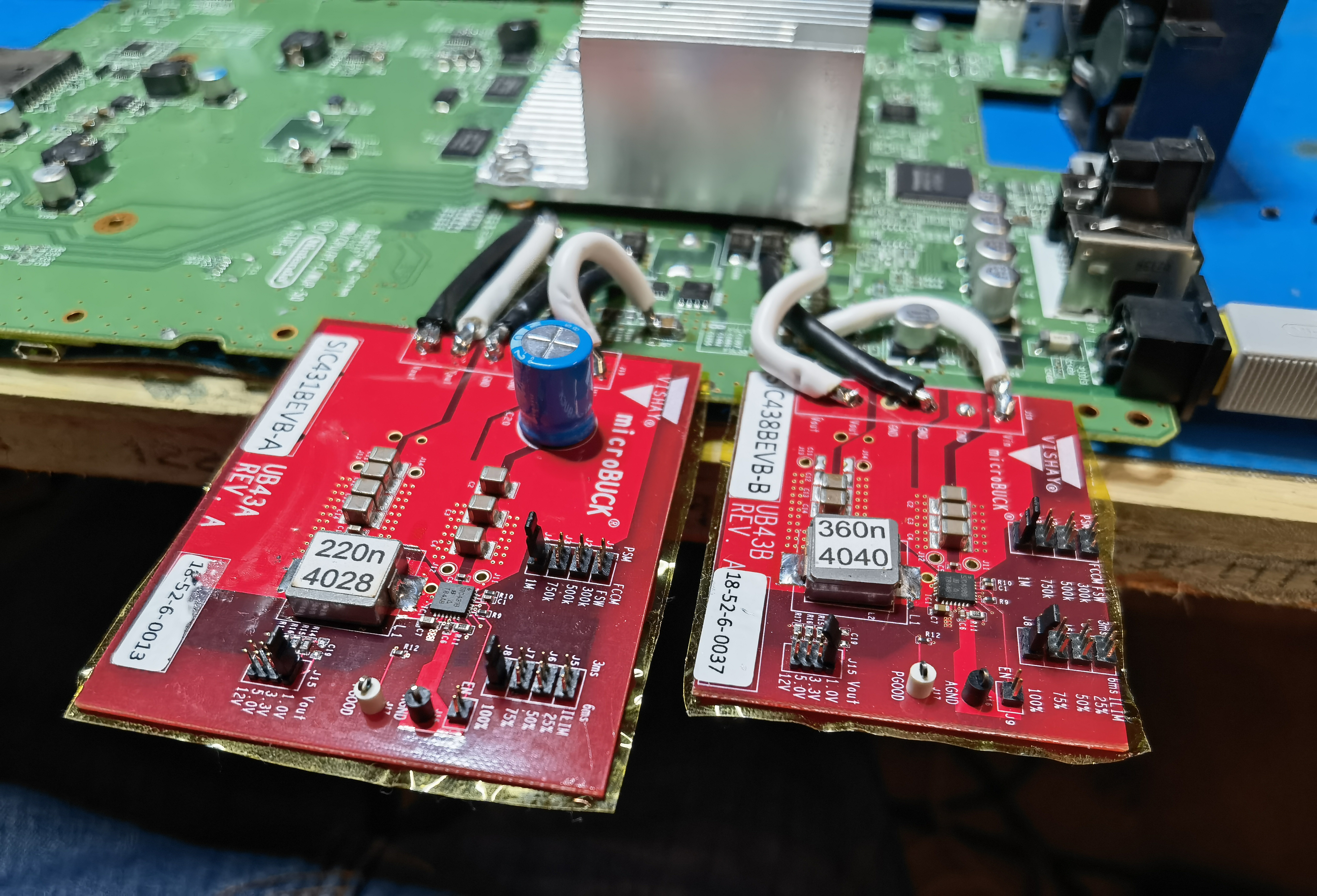
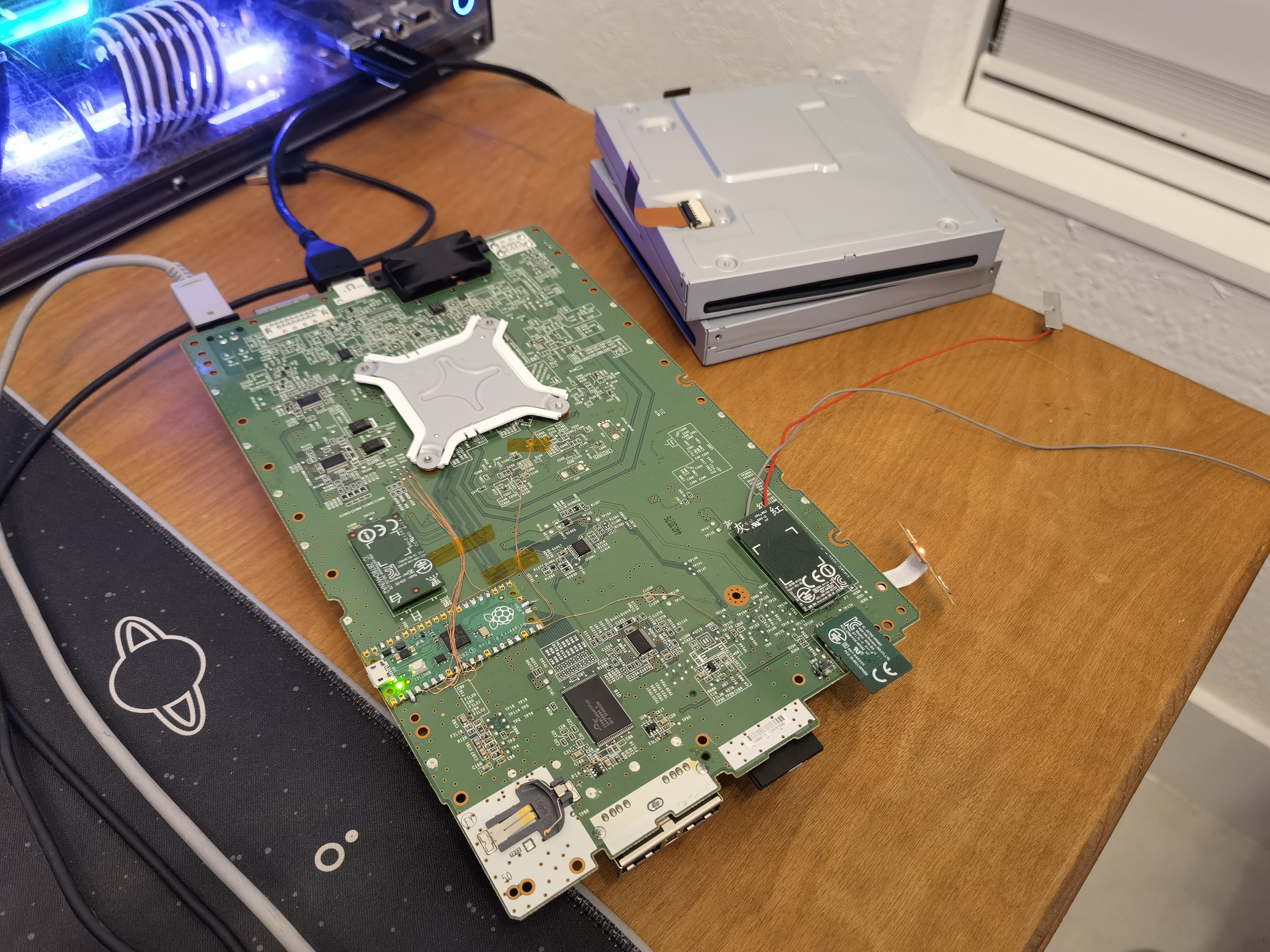
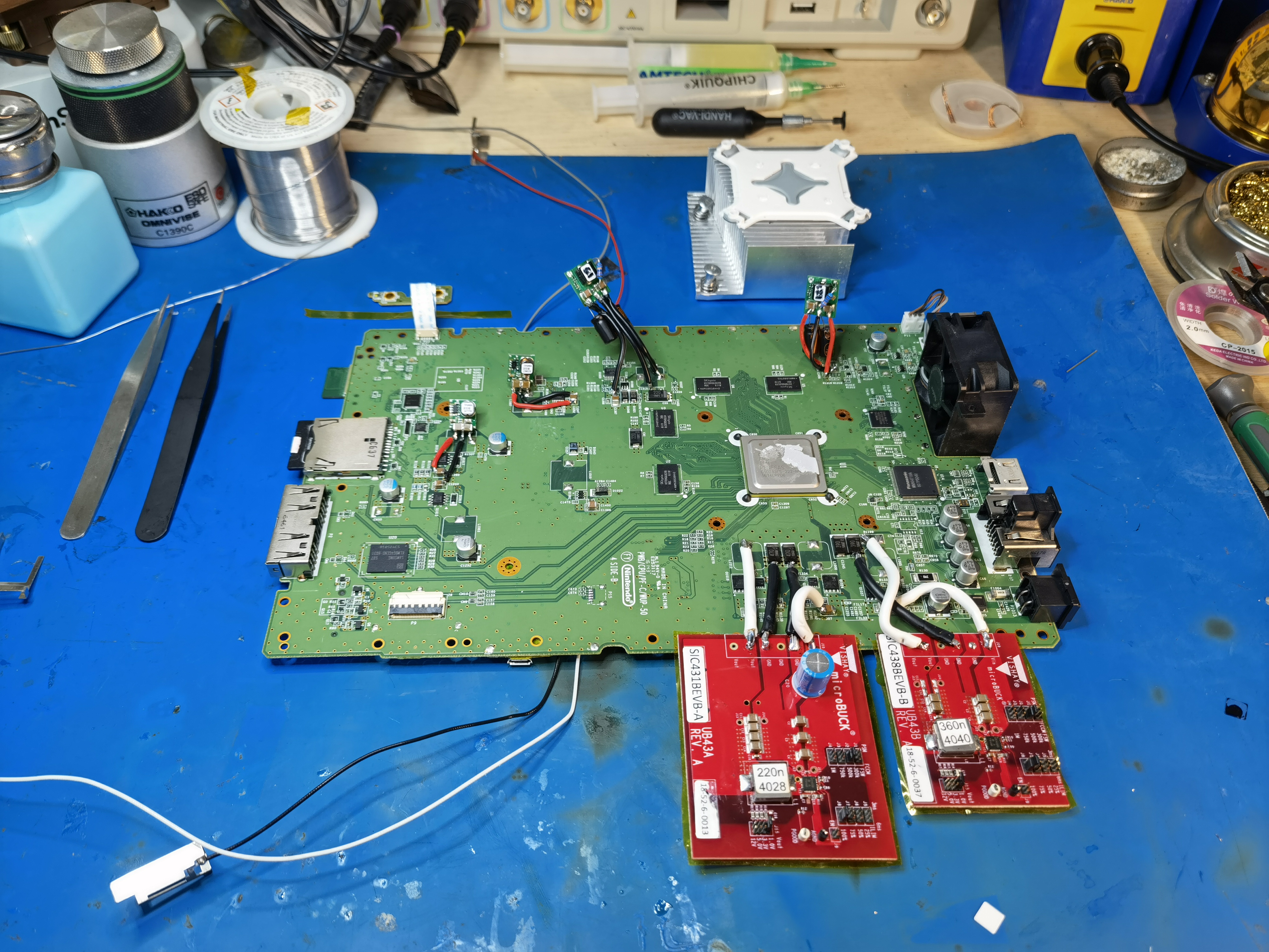
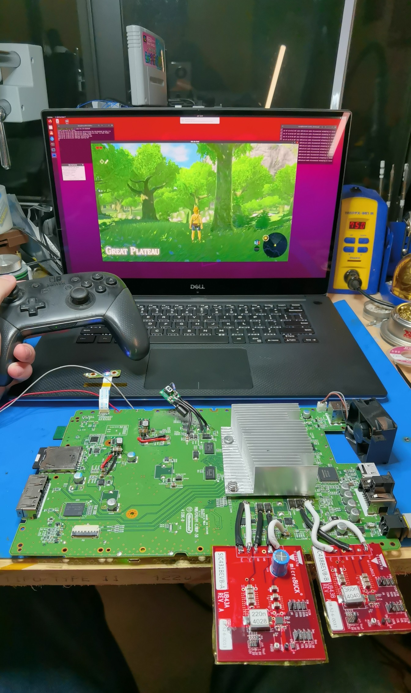
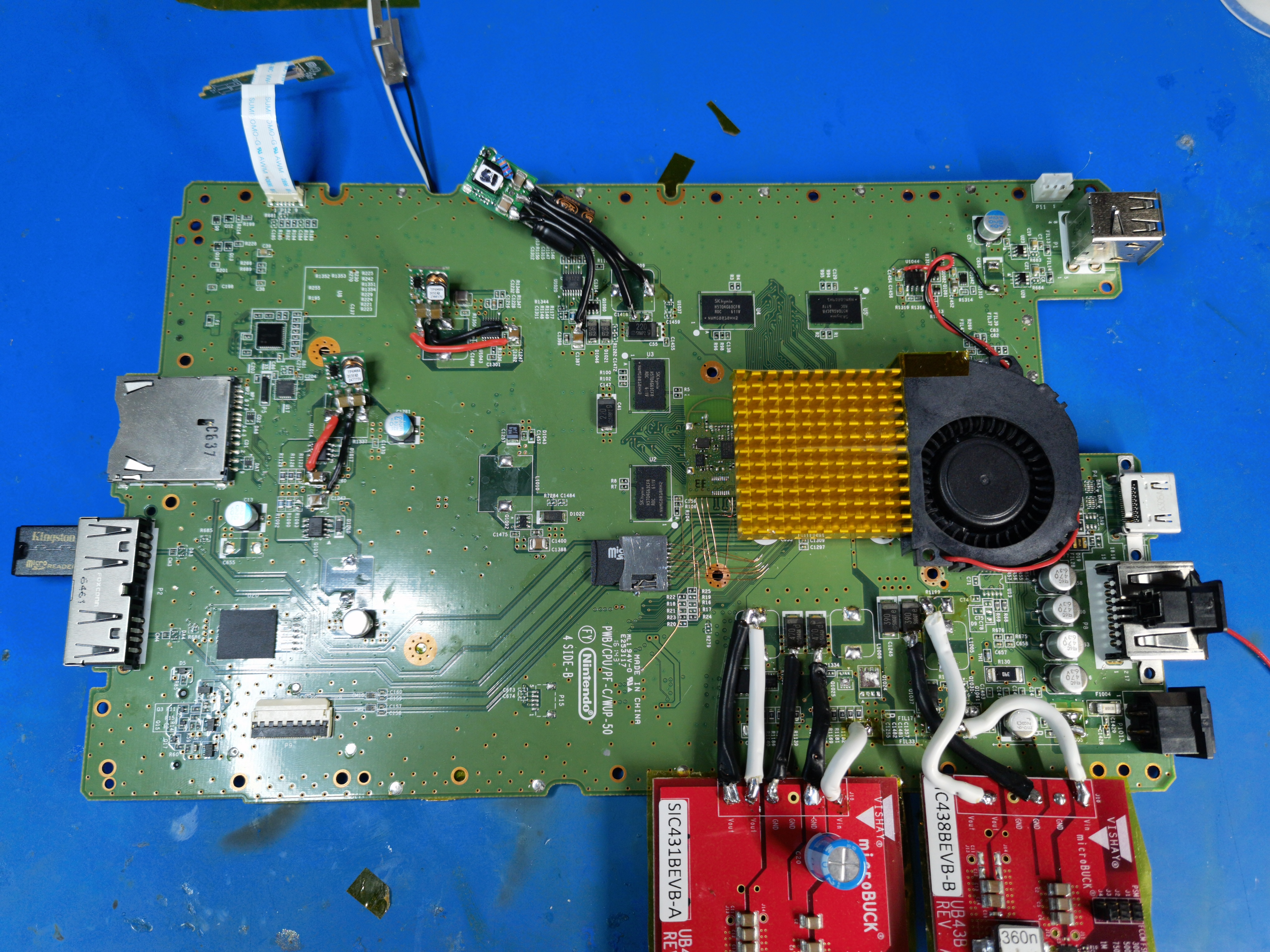
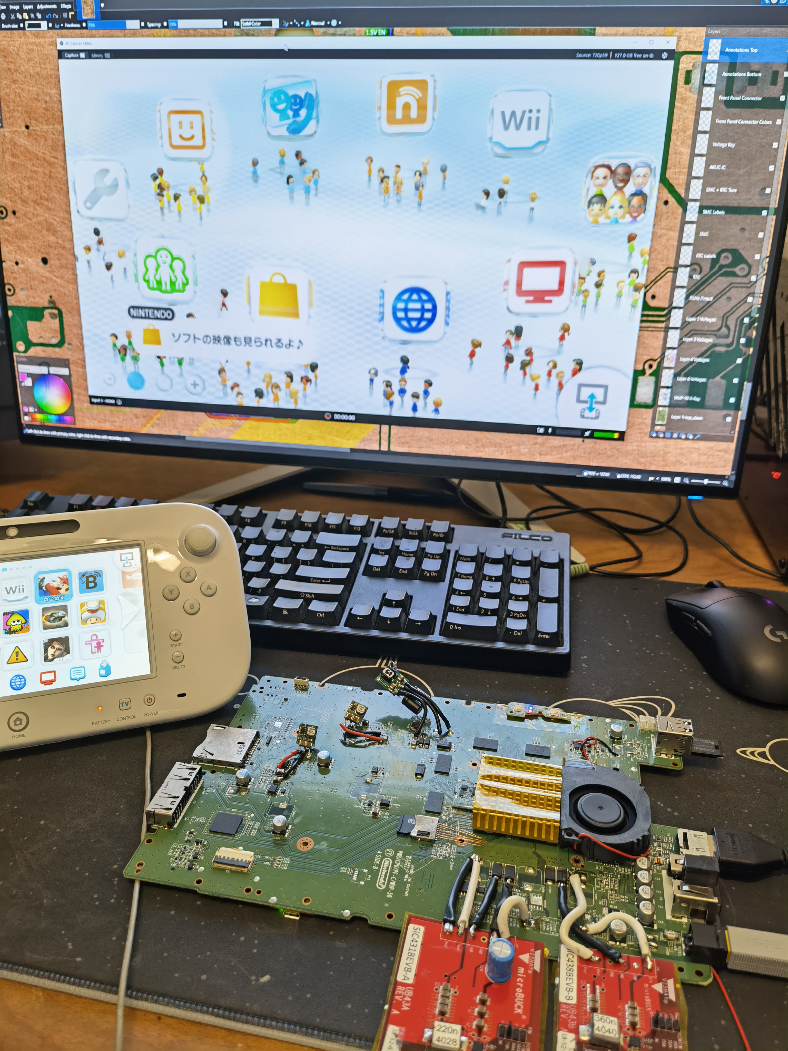
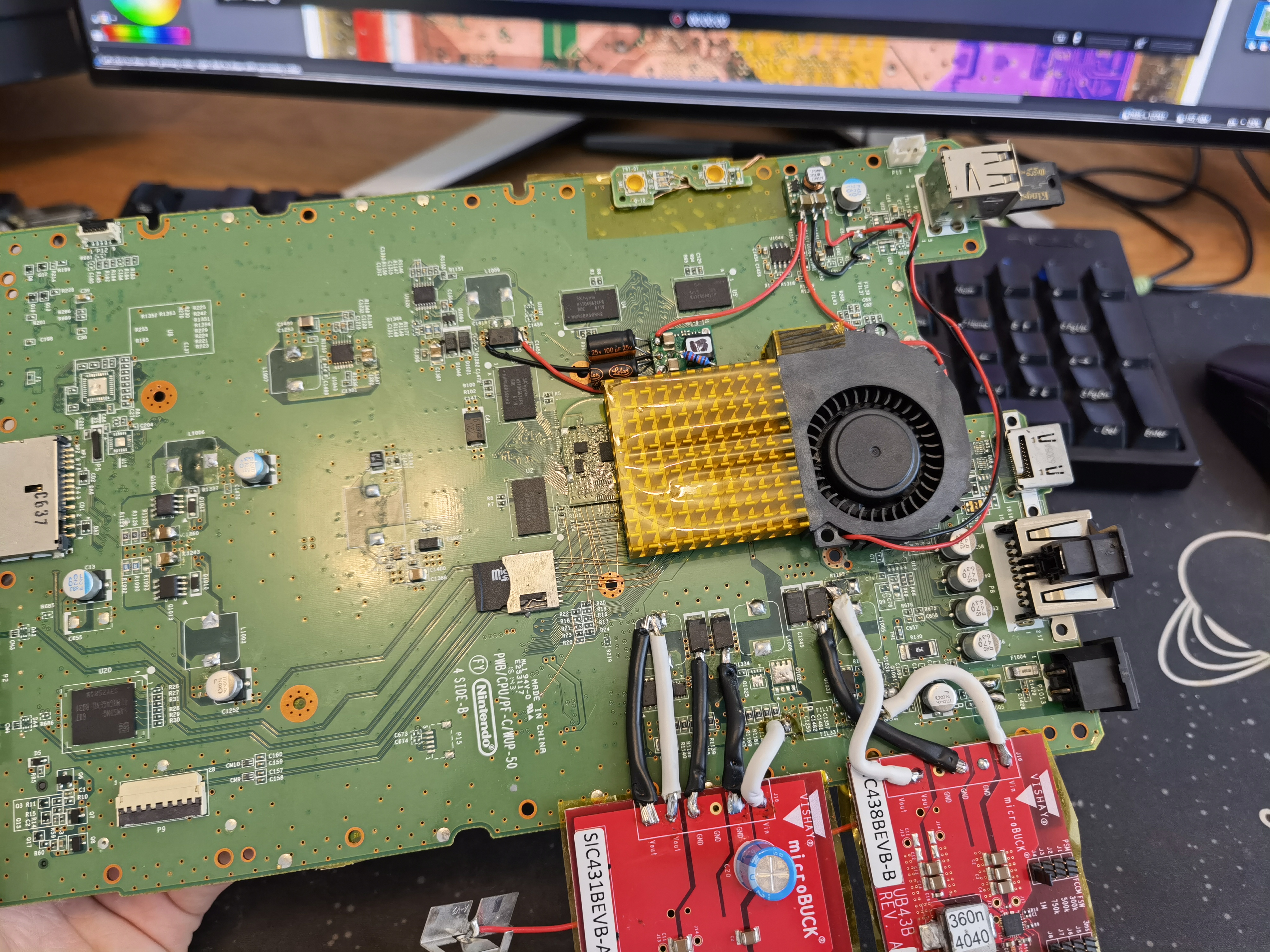
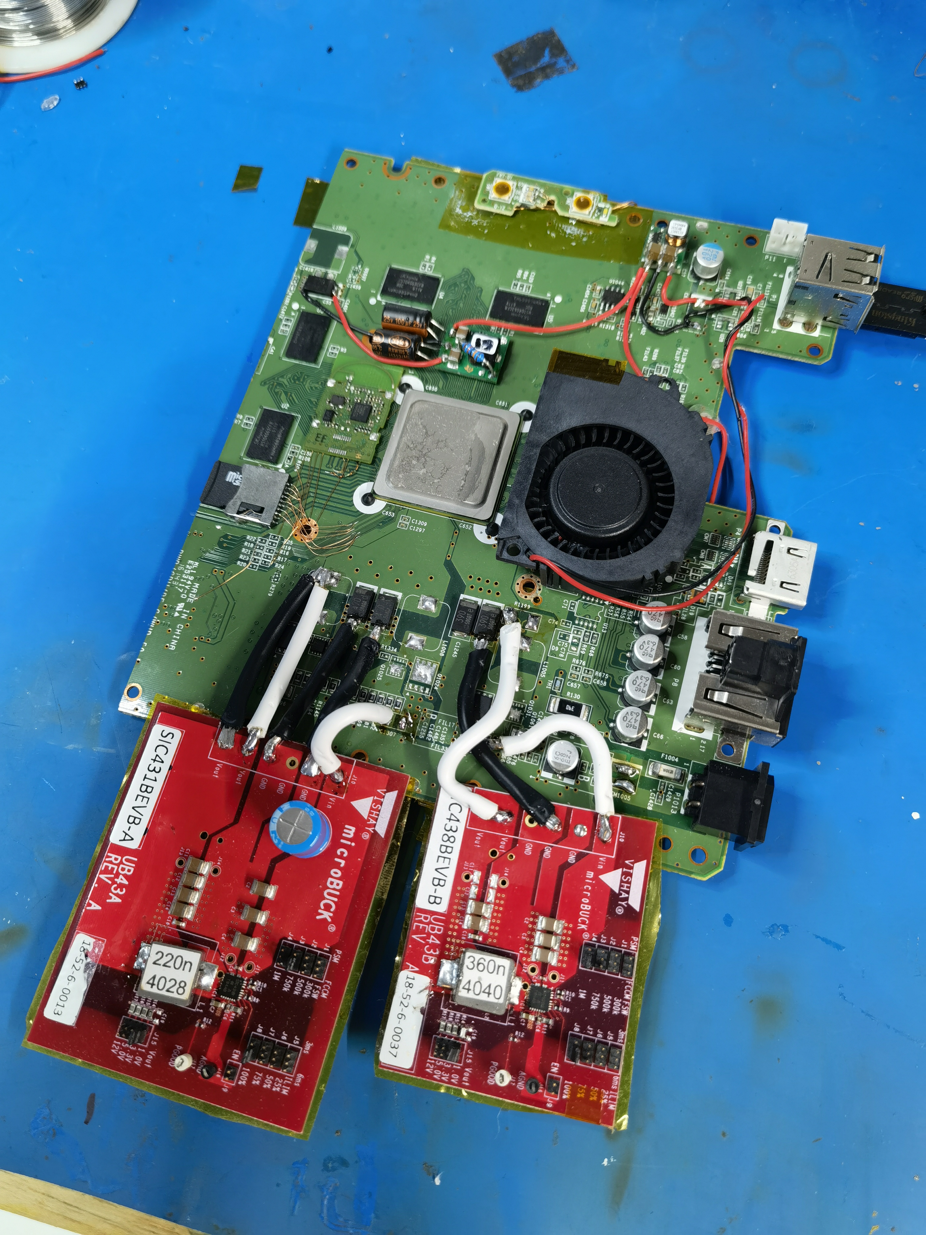
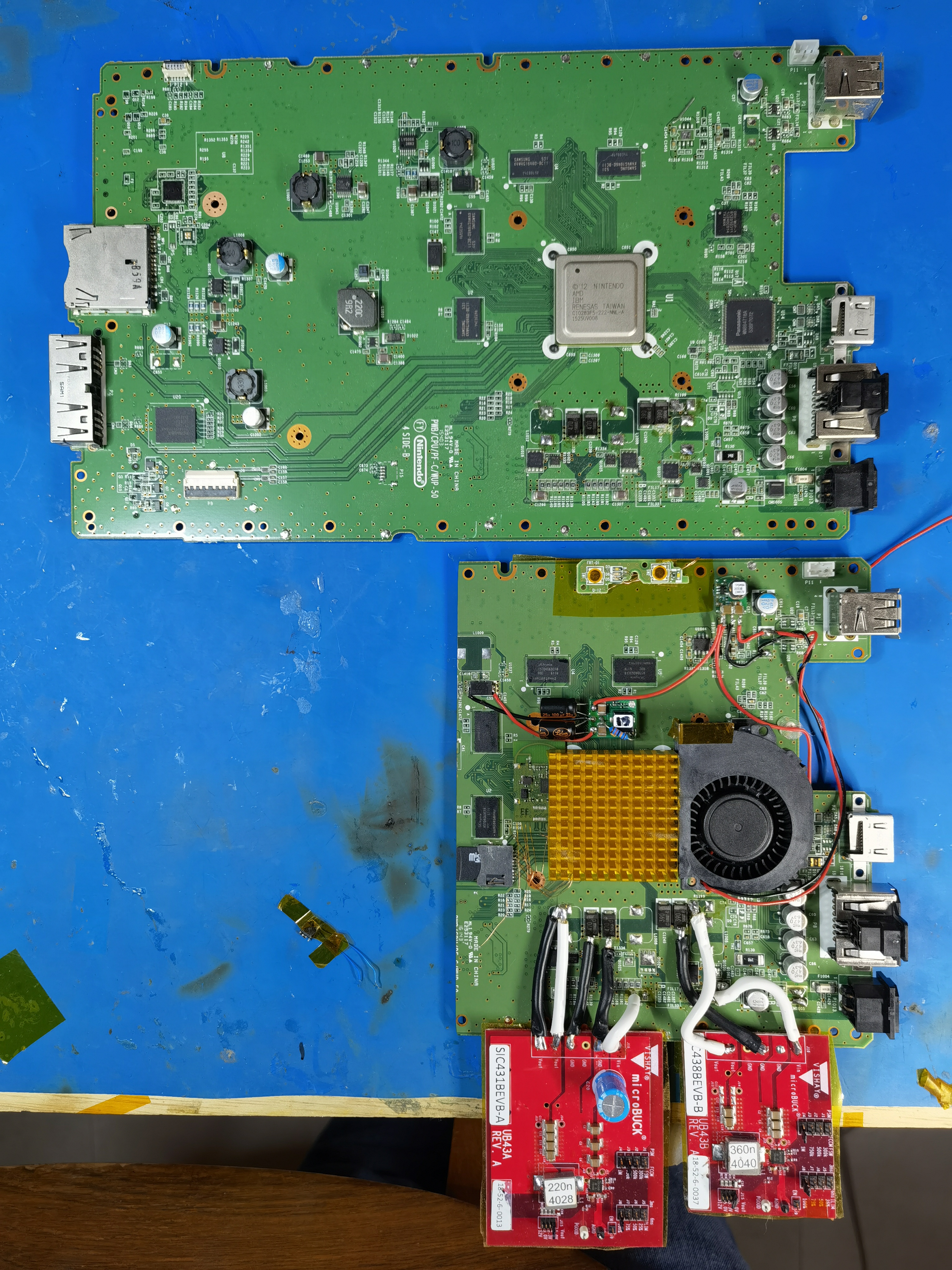
Other regs hooked up. Note: do NOT replicate the 1.25V regulator setup in this image! (top right, near the fan connector)
The 1.25V PTH08080 released its magic smoke when I powered the mobo up!
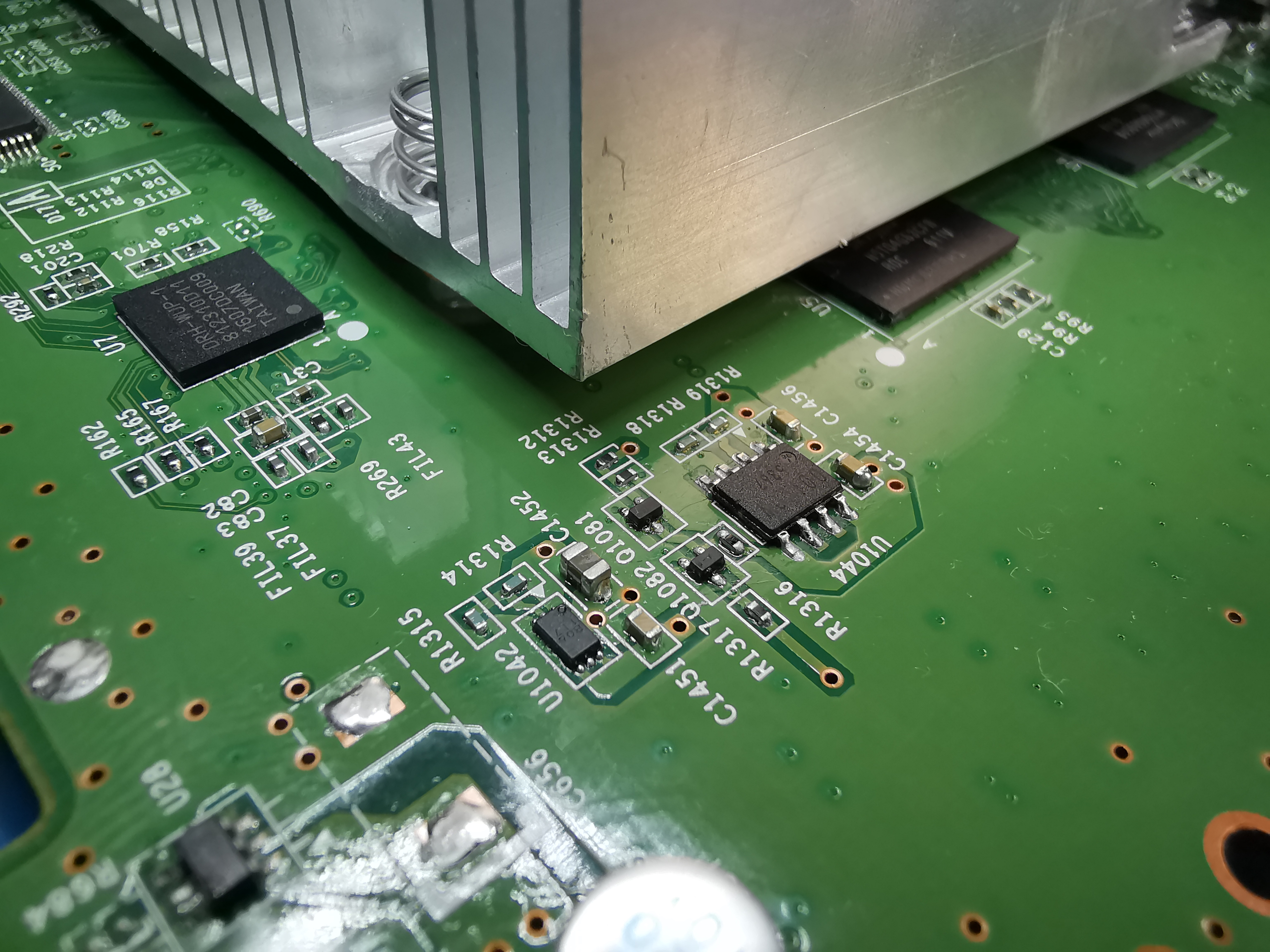
So, I knew the WUP-50 changed the 1.25V rail from a switcher to a linear reg, but I didn't realize that they actually split the rail into 1.25V and 1.1V! I guess the revised DRH-WUP-1 IC needs a second, lower voltage core rail or something.
I think U1044 is the 1.25V LDO and U1042 is the 1.1V LDO, but there are a couple transistors between them that I'm not 100% sure about yet. And it's not like you can replace the DRH BGA if you fry it! So I just left these linear regs in place for my tests. A preliminary trim won't come anywhere near this area, so replacing them isn't a priority.
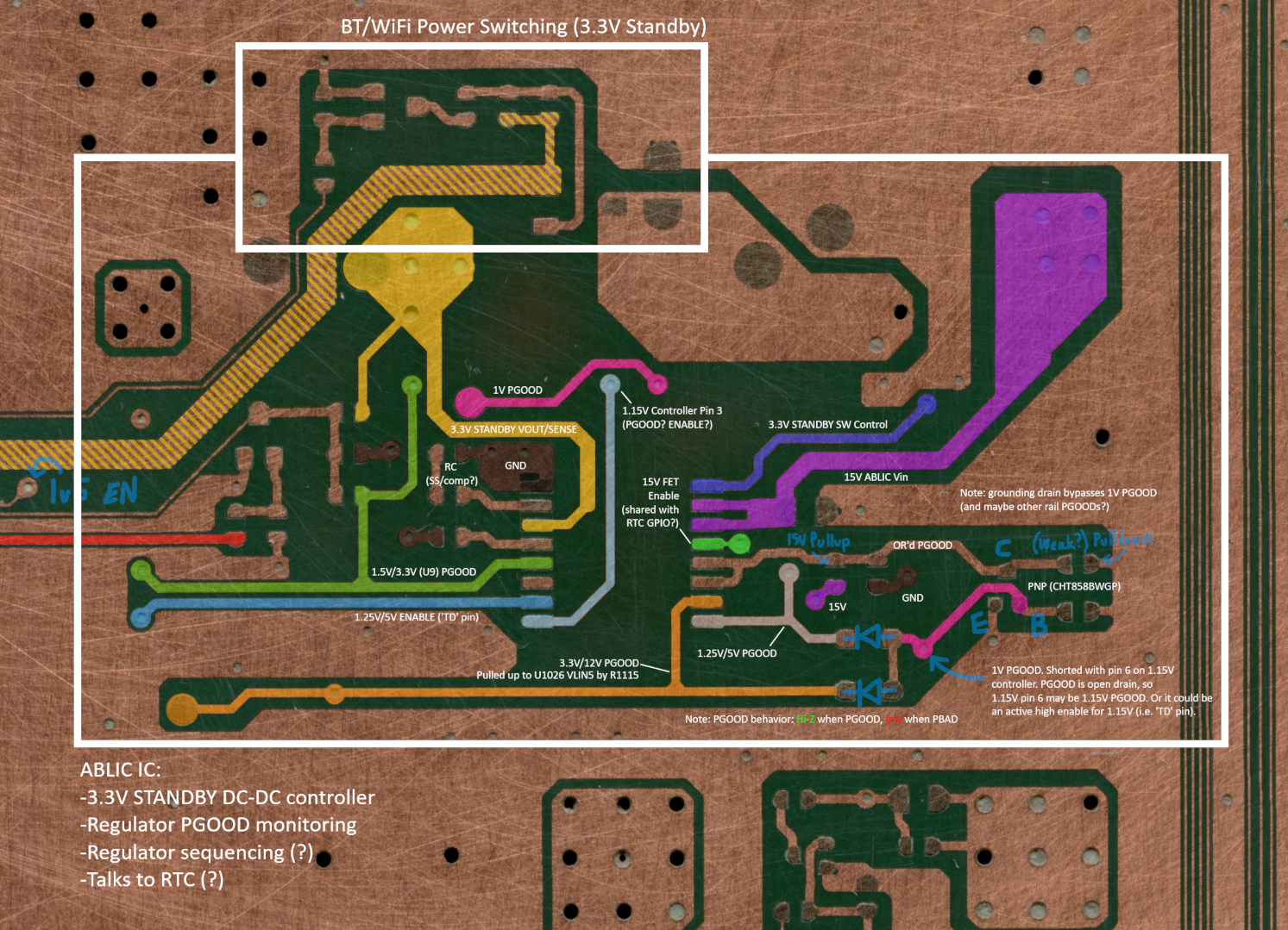
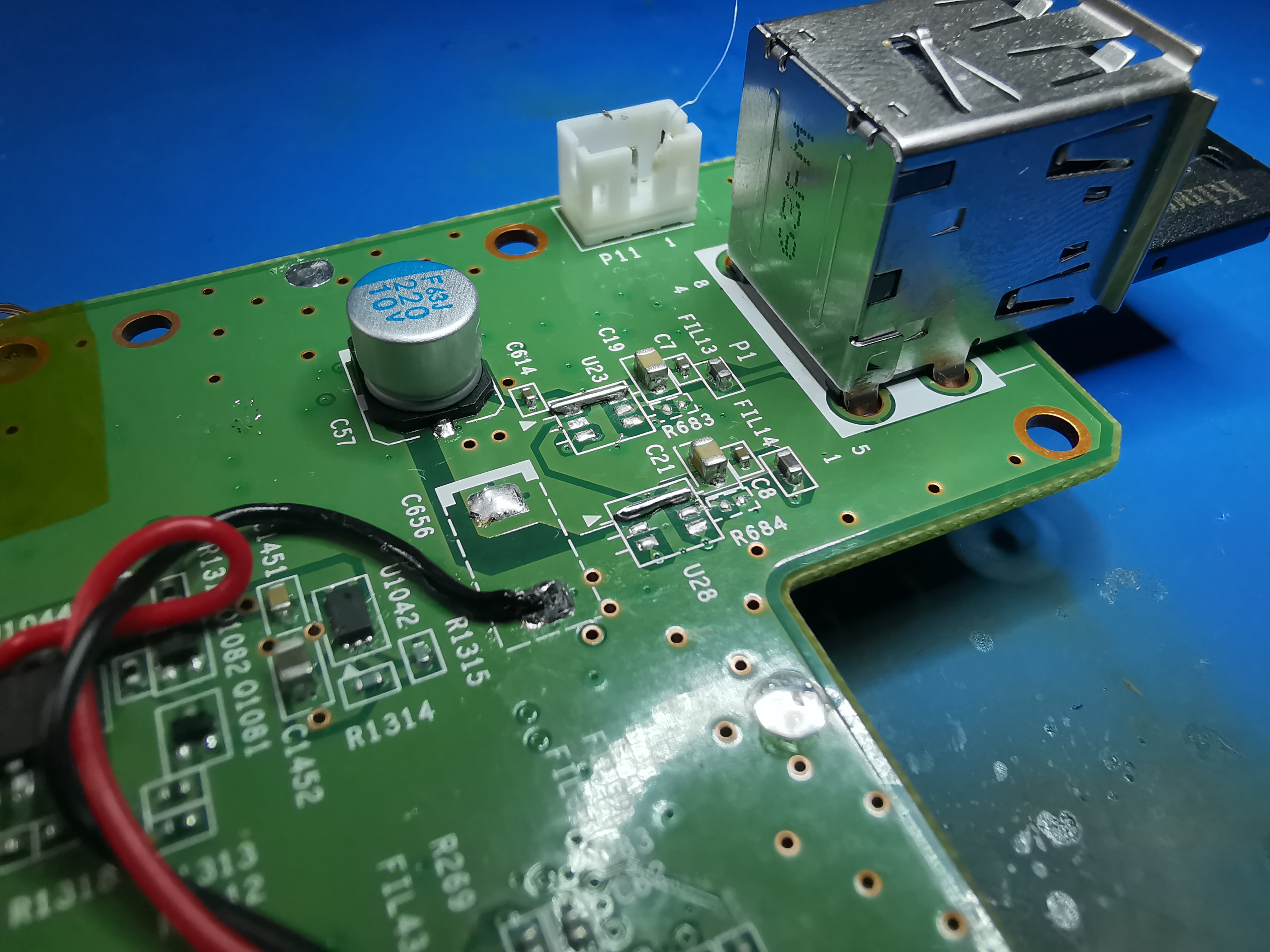
Remember the ABLIC IC? It tag-teams with the RTC to turn on 15V across the mobo and monitors the regulators. Here's how to bypass it on a WUP-50:
 Without tying them high, the power led just blinks red and the system doesn't boot.
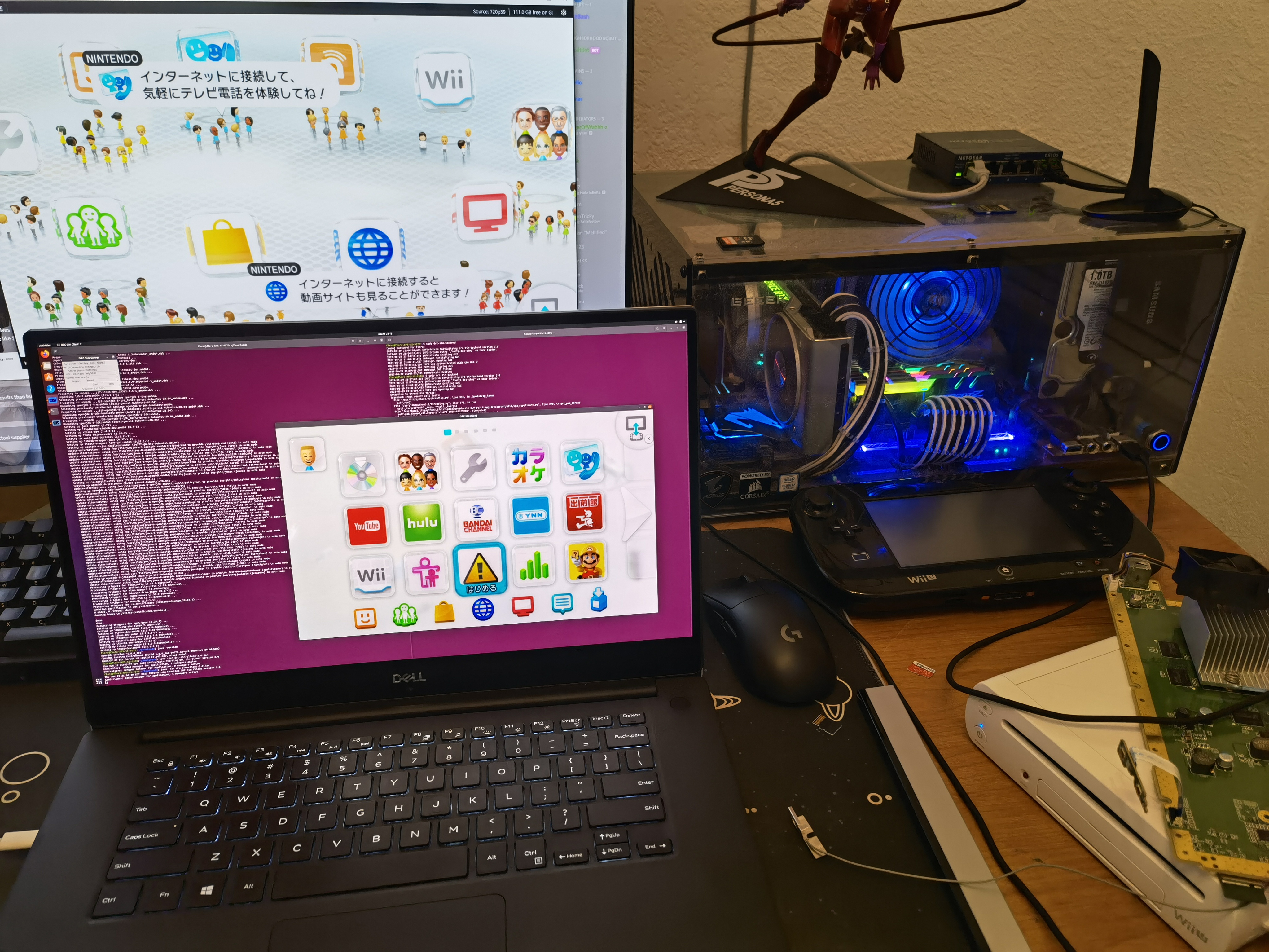
But with the standby rail shorted to the 3.3V reg, and the PGOODs all tied high... something magical happens:
The console turns on by itself (no power button press required) and de_Fuse automatically works its magic (flashing red and blue LEDs). Success! First Wii U on custom regulators.
I still need to trace all the PGOOD lines back to the SOC. Obviously shorting ABLIC pads to 3.3v isn't gonna work when that whole section of the mobo is trimmed away! Also, the red LED still blinks a couple times when booting. I need to track down the root cause of that (maybe a 12v sense line?) because any weirdness in the boot process has the potential to mess with de_Fuse.
Besides that stuff, the next major to-do is relocating the wireless modules, which @Crazzyleprechaun has been making good headway on. Then I'll cut out an SMC/RTC daughterboard from a donor Wii U (I confirmed the chips are swappable) and relocate that, and finally relocate the NANDs. Almost there!
Big news! WUP-50s only draw ~9A on the 1V line. This is 5 to 6 amps less than a WUP-01! So it appears there was a dieshrink (or some other silicon optimization) on the later revs with smaller MCMs.
1A @ 1V = 1W, so this is a ~6W power save at the mobo level (and closer to 7W if you take into account regulator losses.)
But the harsh reality is that WUP-50s are very uncommon. For every one WUP-50 on eBay, there are about a hundred WUP-01s. Focusing solely on the WUP-50 doesn't align with the goal of democratizing Wii U portablizing.
Luckily, the WUP-50 is very similar to the WUP-01, besides the routing changes around the SOC and RAM. SMC/RTC/eMMC/NAND/wireless routing is almost 1:1, and crucially, most test pads are still present. So the relocations and trims for WUP-01 and WUP-50 will be very similar, and the majority of my WUP-01 compendium work applies directly to the WUP-50.
Speaking of compendium work, I've fully pinoutted the SMC, RTC, and ABLIC.
Here's the gist of this RE work:
- The SMC handles the front panel IO (power/eject buttons, LEDs), optical drive GPIOs, some mysterious wireless module GPIOs, USB port protection, and adjustment of the onboard 1V reg. It is connected to the SOC over I2C, and to the RTC via an unknown bus (probably also I2C). The SMC and RTC also share a 1Hz heartbeat timer signal and a couple reset/power-on type signals.
- The RTC handles power-up and regulator monitoring (along with the clock functions.) It controls the PFET that switches 15V to all the onboard regulators and listens to a PGOOD signal generated by the ABLIC IC. It also enables the 1.5V DDR regulator and somehow controls power to the 2.4GHz wireless module. It's connected to the SOC over EXI.
- The ABLIC IC is on the bottom of the mobo. It's a custom part as far as I can tell and incorporates a bunch of stuff. It's the DCDC controller for the standby 3.3V reg, aggregates and/or monitors PGOOD signals from all the onboard regulators, piggybacks on the 15V PFET enable, and possibly does some regulator sequencing.
In keeping with the plan I outlined last year, I decided to tackle custom regs next. @Redherring32 turned me on to some sweet Vishay regulators (SiC43X family) which are way cheaper and simpler than the goofy TI regs on my old reg board. In the interest of time, I picked up some evaluation boards for two of them along with some smaller regs for the low-current rails.
- SiC431B for 1V (24A output)
- SiC438B for 1.15v (8A output)
- PTH08080 for 1.5V, 1.25V (2.25A, super overkill for 1.25v but whatever)
- TPSM84203 and TPSM84205 for 3.3V and 5V (1.5A output)
Full disclosure, I did have to swap inductors and feedback resistors on the EVBs to get the right voltages/currents. Using maximum thickness wire (~12AWG), since in my experience the Wii U really doesn't like voltage droop.
Other regs hooked up. Note: do NOT replicate the 1.25V regulator setup in this image! (top right, near the fan connector)
The 1.25V PTH08080 released its magic smoke when I powered the mobo up!
So, I knew the WUP-50 changed the 1.25V rail from a switcher to a linear reg, but I didn't realize that they actually split the rail into 1.25V and 1.1V! I guess the revised DRH-WUP-1 IC needs a second, lower voltage core rail or something.
I think U1044 is the 1.25V LDO and U1042 is the 1.1V LDO, but there are a couple transistors between them that I'm not 100% sure about yet. And it's not like you can replace the DRH BGA if you fry it! So I just left these linear regs in place for my tests. A preliminary trim won't come anywhere near this area, so replacing them isn't a priority.
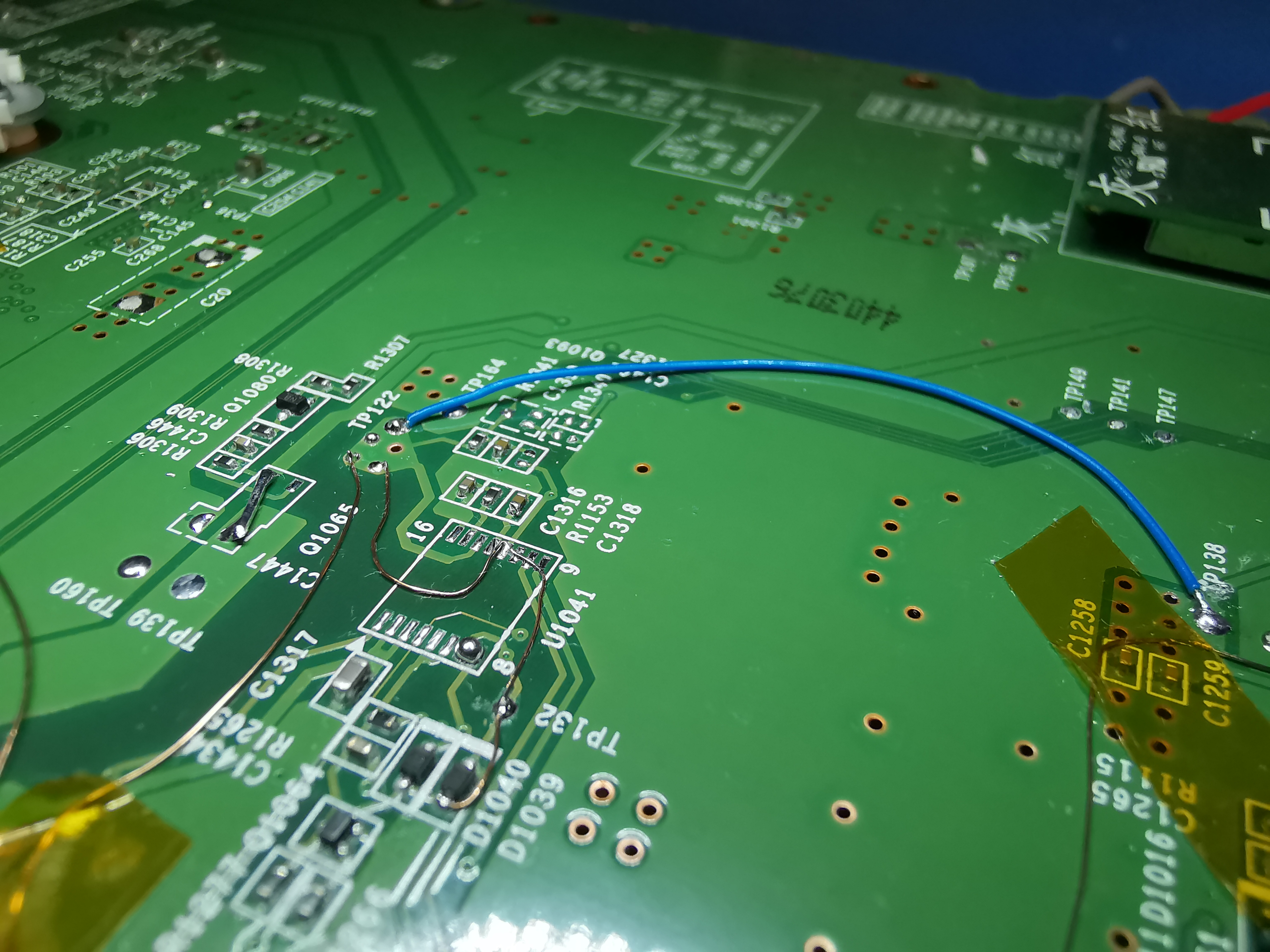
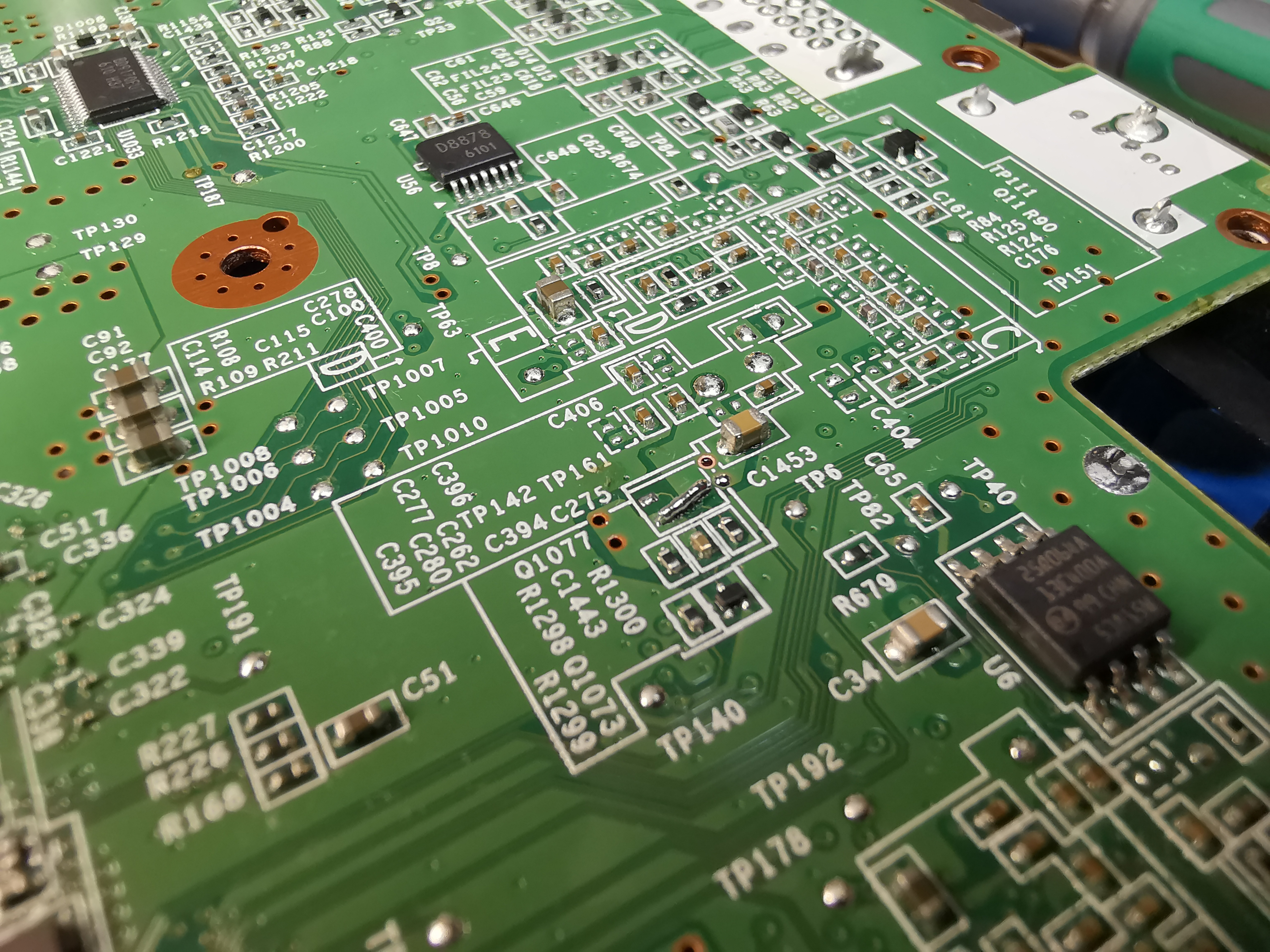
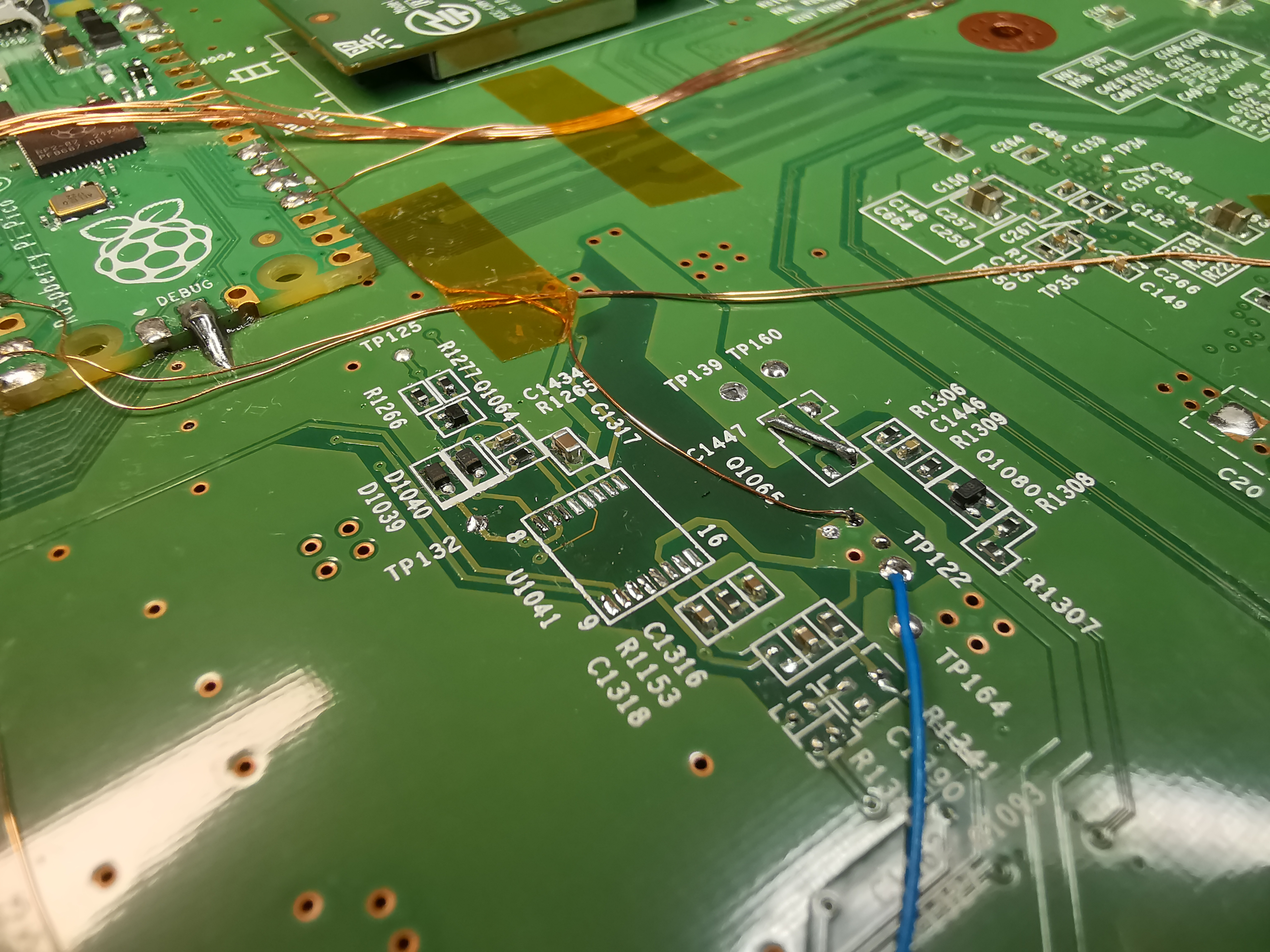
Remember the ABLIC IC? It tag-teams with the RTC to turn on 15V across the mobo and monitors the regulators. Here's how to bypass it on a WUP-50:
- Remove the ABLIC IC (U1041)
- Remove R1340 (The WUP-50 actually has Q1093 depopulated, so the ABLIC-RTC PGOOD signal is already partially decoupled from the regs. But removing R1340 completes the disconnection.)
- Short 3.3V_STANDBY to 3.3V (blue wire)
- Remove Q1065 and bridge across the source/drain pads as shown (this is the 2.4GHz module power switch)
- Short ABLIC pins 7, 8, 9, 10, 11, and 12, as well as the anodes of D1039/D1040, to 3.3V
- Finally, to get 15V across the mobo with the ABLIC gone, cut the trace between the 15V PFET gate via and R1281, and tie the gate to GND.
Without tying them high, the power led just blinks red and the system doesn't boot.But with the standby rail shorted to the 3.3V reg, and the PGOODs all tied high... something magical happens:
The console turns on by itself (no power button press required) and de_Fuse automatically works its magic (flashing red and blue LEDs). Success! First Wii U on custom regulators.
I still need to trace all the PGOOD lines back to the SOC. Obviously shorting ABLIC pads to 3.3v isn't gonna work when that whole section of the mobo is trimmed away! Also, the red LED still blinks a couple times when booting. I need to track down the root cause of that (maybe a 12v sense line?) because any weirdness in the boot process has the potential to mess with de_Fuse.
Besides that stuff, the next major to-do is relocating the wireless modules, which @Crazzyleprechaun has been making good headway on. Then I'll cut out an SMC/RTC daughterboard from a donor Wii U (I confirmed the chips are swappable) and relocate that, and finally relocate the NANDs. Almost there!
Ok, if you remove and bypass Q1077 and Q1078 as shown, you no longer need any PGOOD jumper wires near the ABLIC.
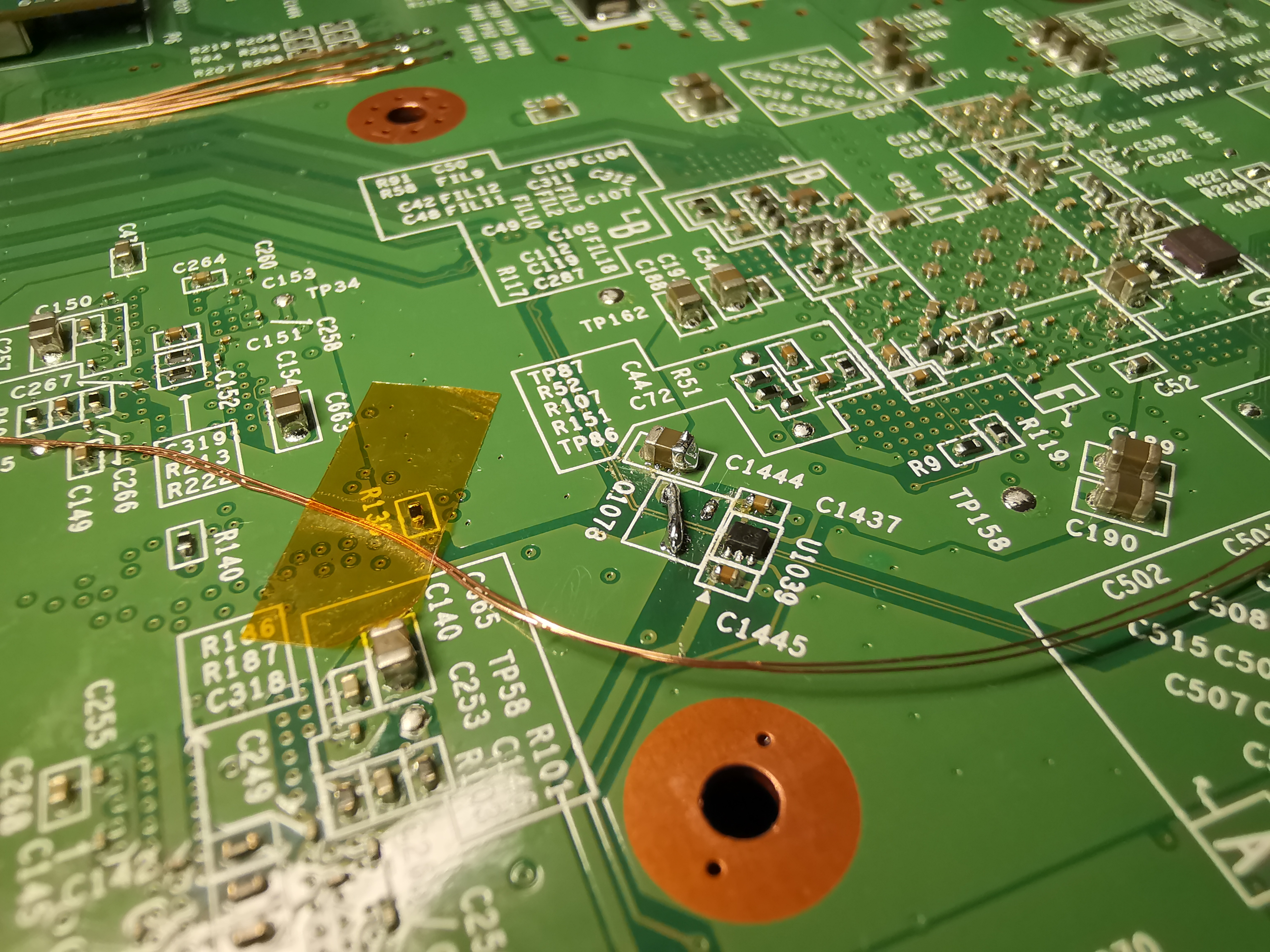
Explanation: 1.25V/5V PGOOD enables Q1077 to provide 3.3V to the video encoder and DRH. 3.3V/12V PGOOD enables Q1078 to provide 1.5V to the Latte.
Added bonus is that the three-blink red LED at boot seems to be gone...?
Explanation: 1.25V/5V PGOOD enables Q1077 to provide 3.3V to the video encoder and DRH. 3.3V/12V PGOOD enables Q1078 to provide 1.5V to the Latte.
Added bonus is that the three-blink red LED at boot seems to be gone...?
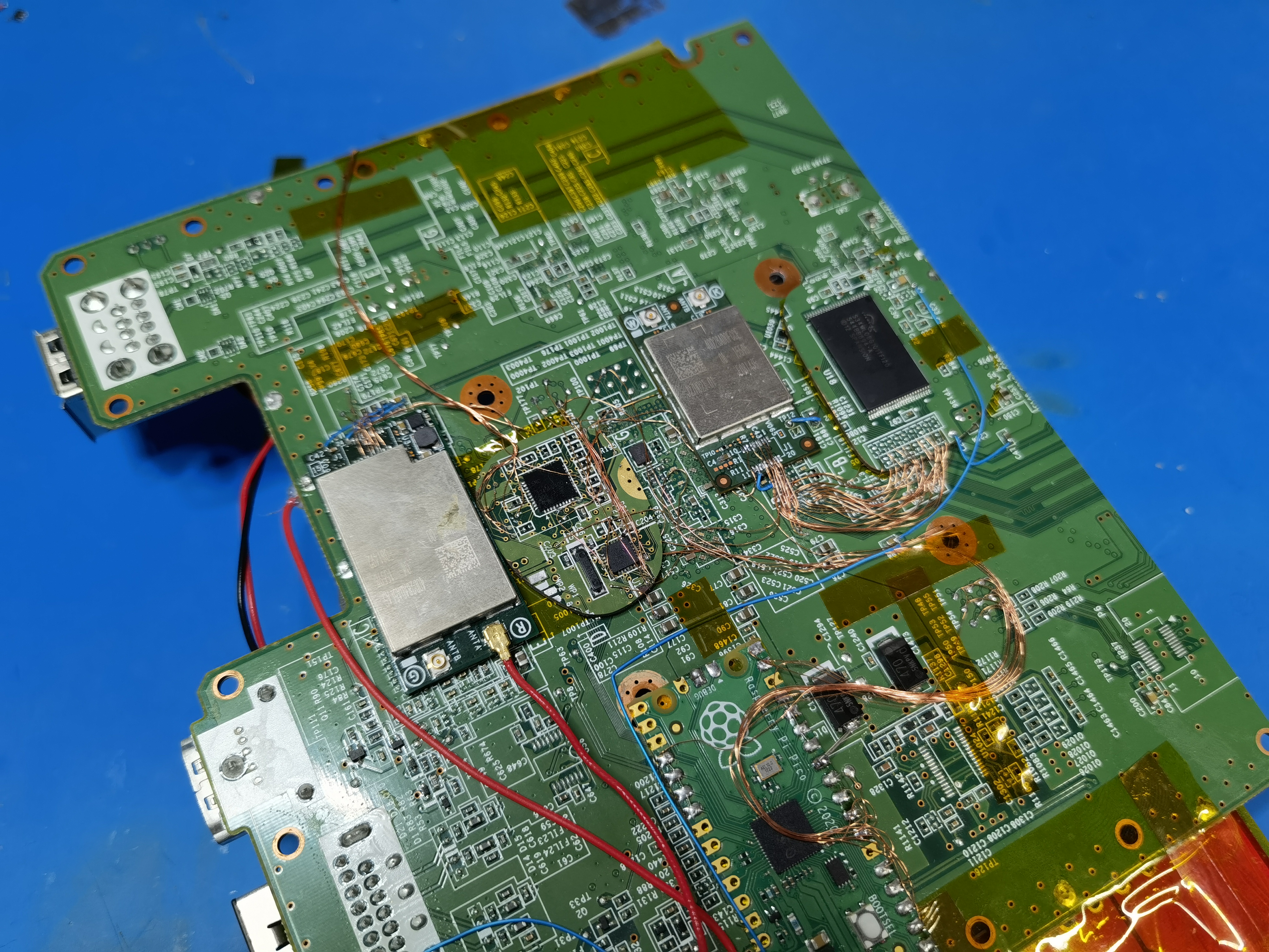
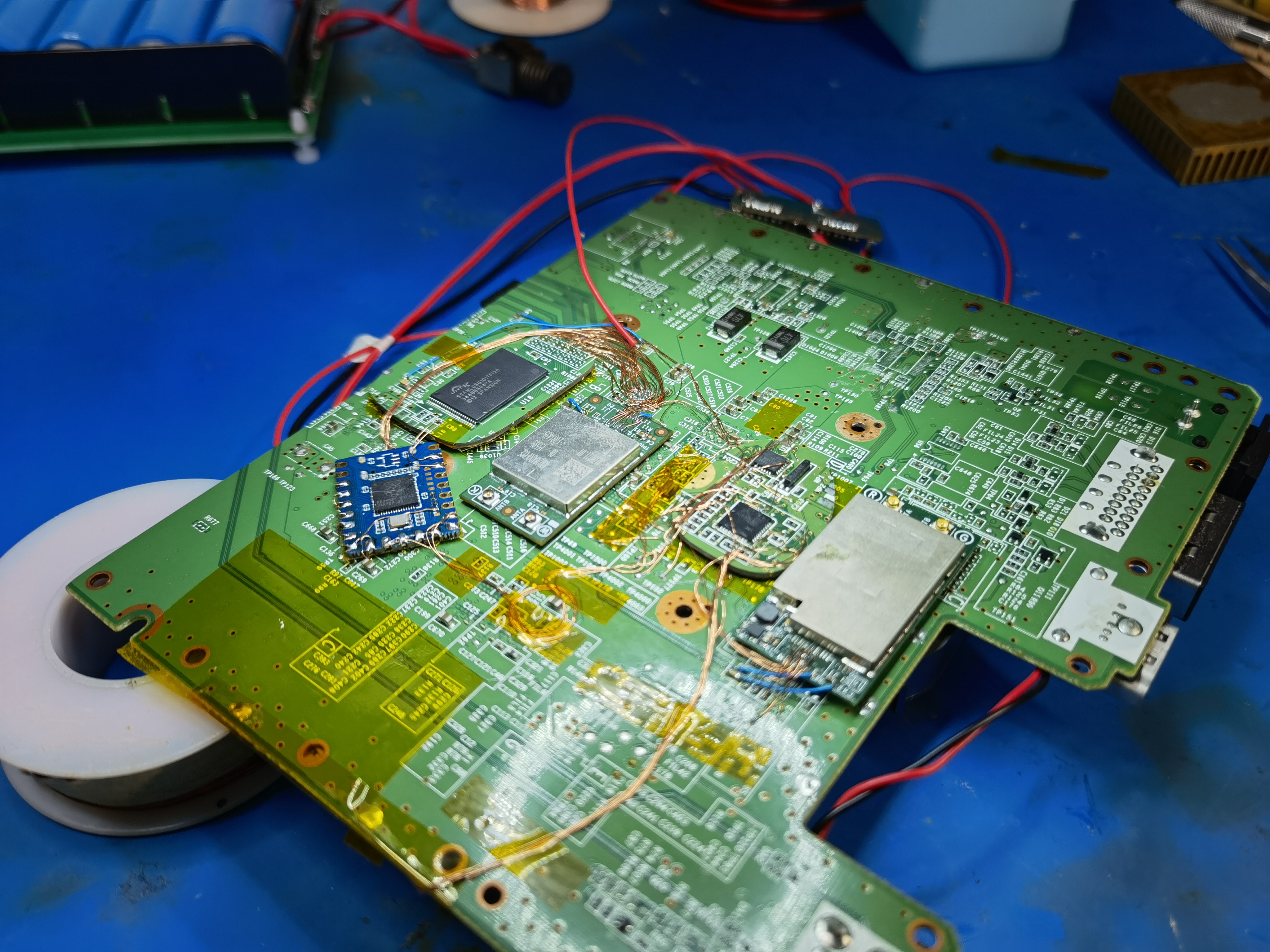
I relocated both the 5GHz GamePad module and the 2.4GHz WiFi module! Both worked first try-- if you keep the wires short and neat, it's really not bad. @Crazzyleprechaun has also done these relocations on his test mobo, so we know it's replicable!
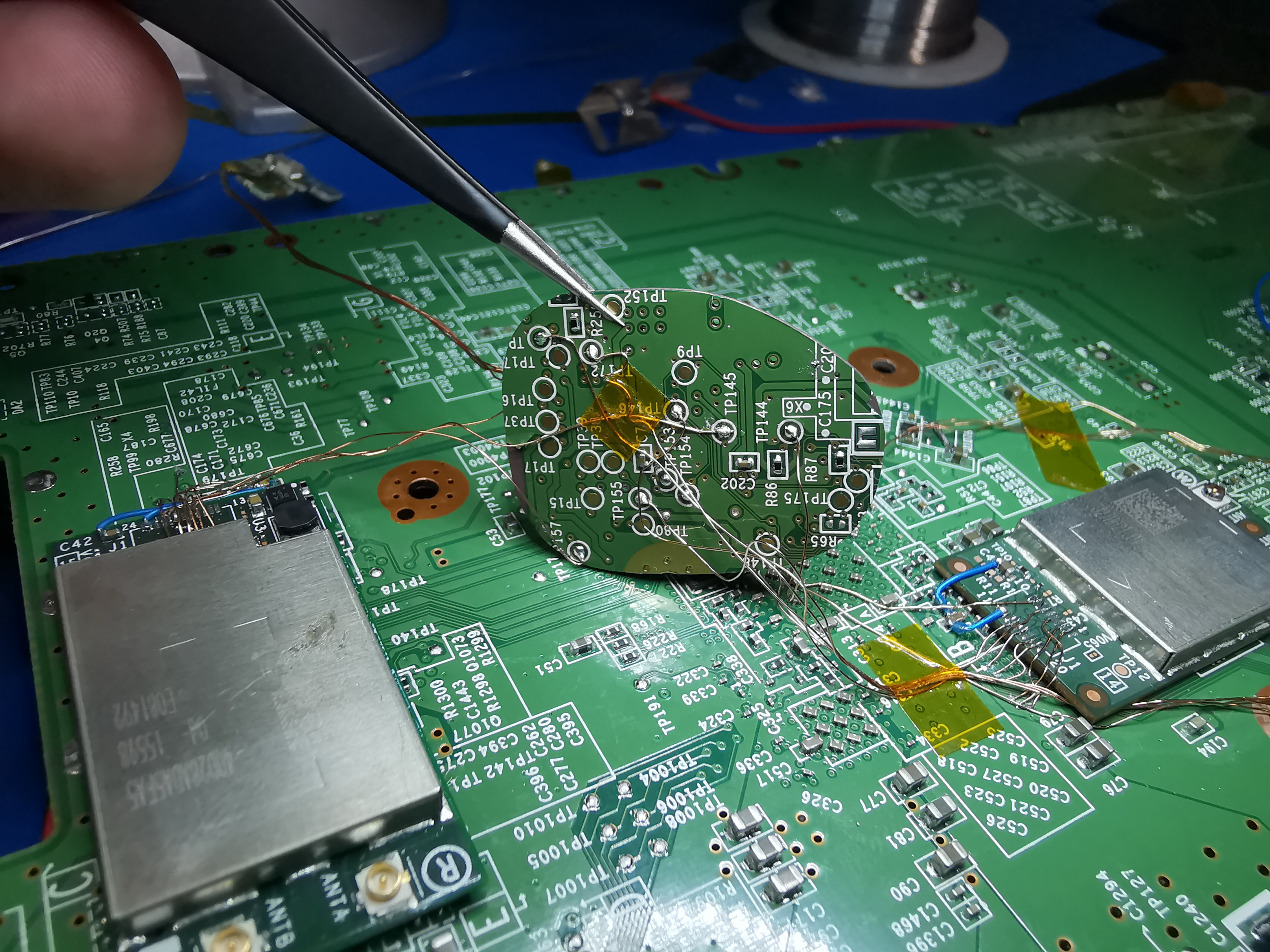
Connectors wired up under the microscope. The GamePad module needs some deadbugged pullup/pulldown resistors.
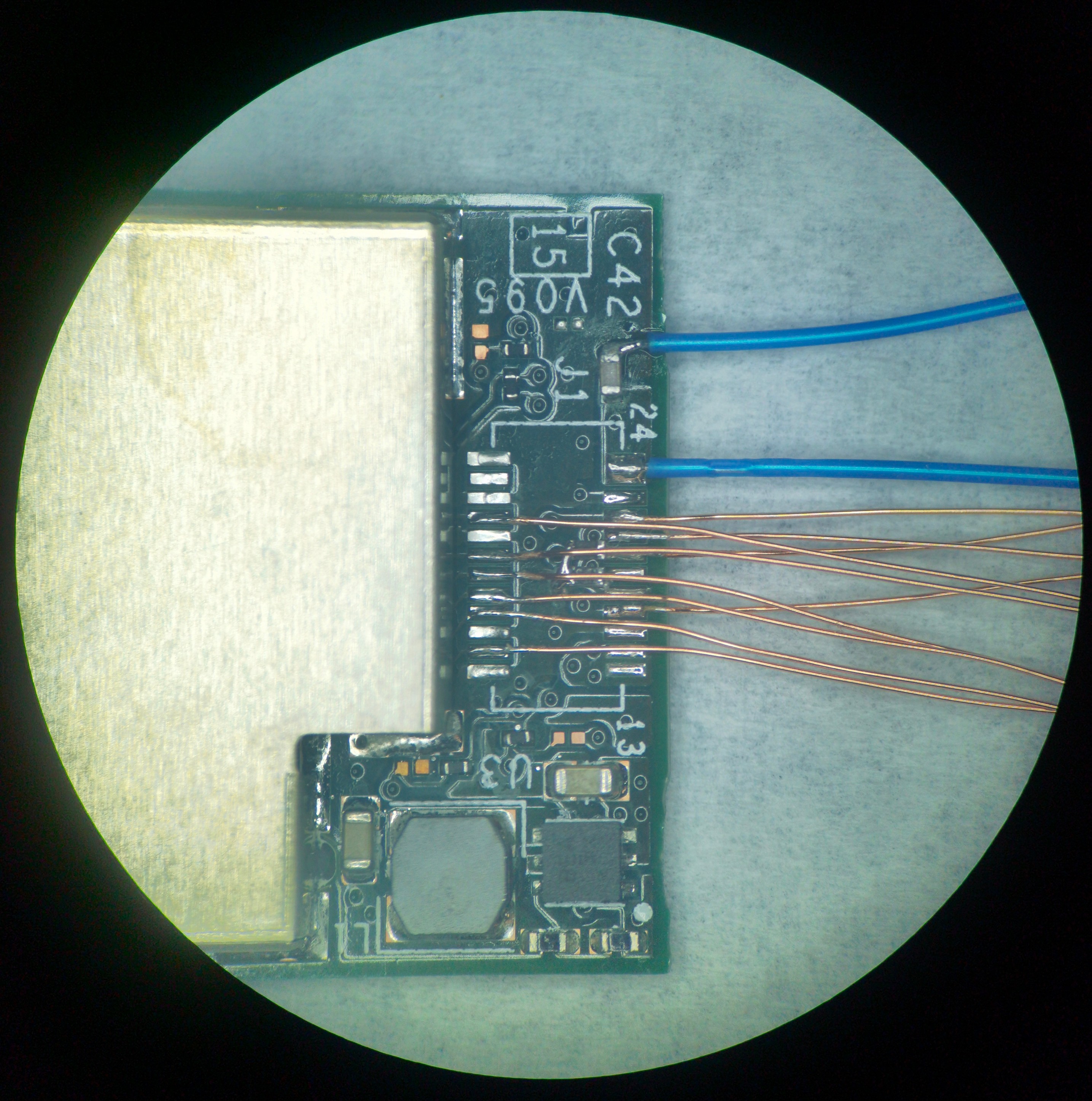
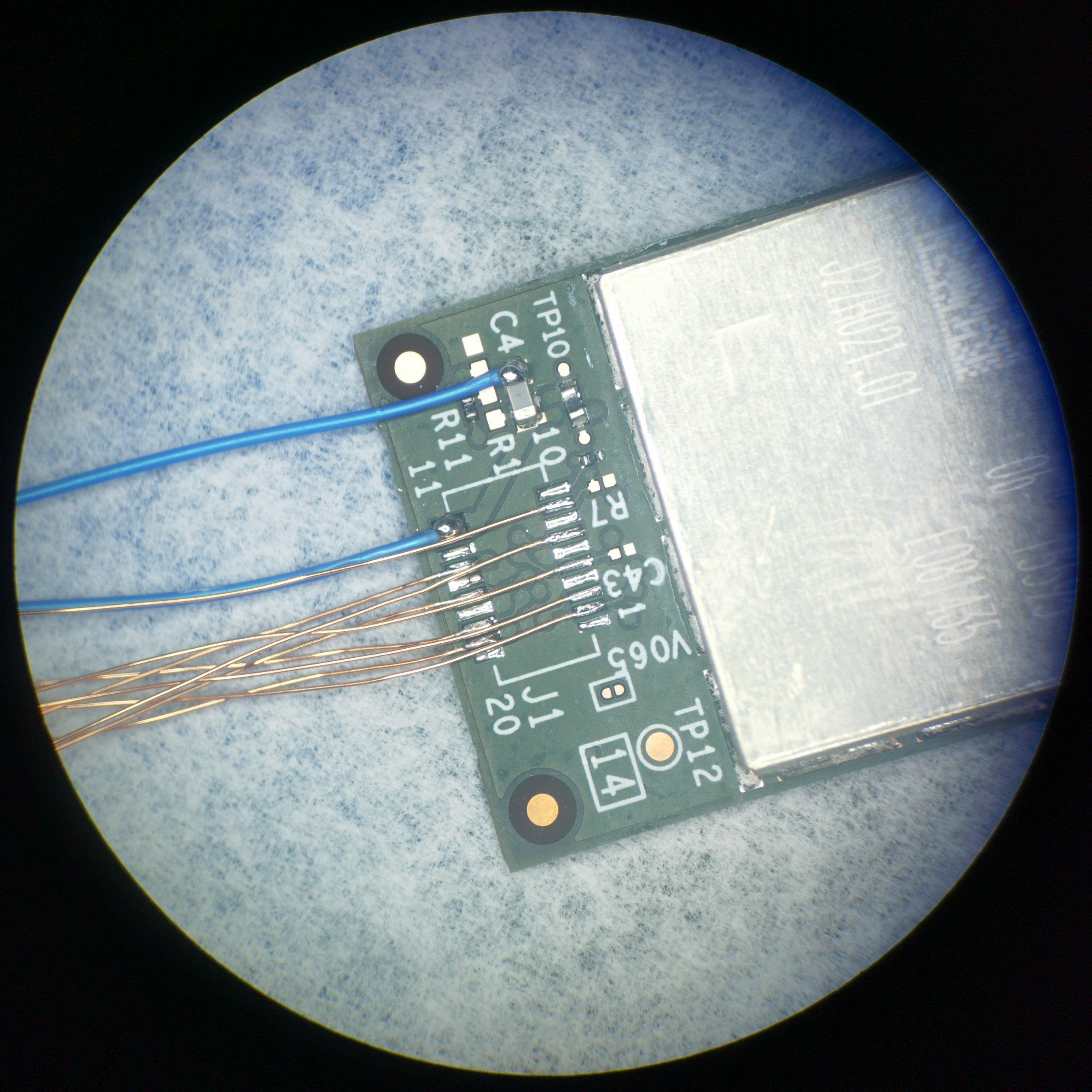
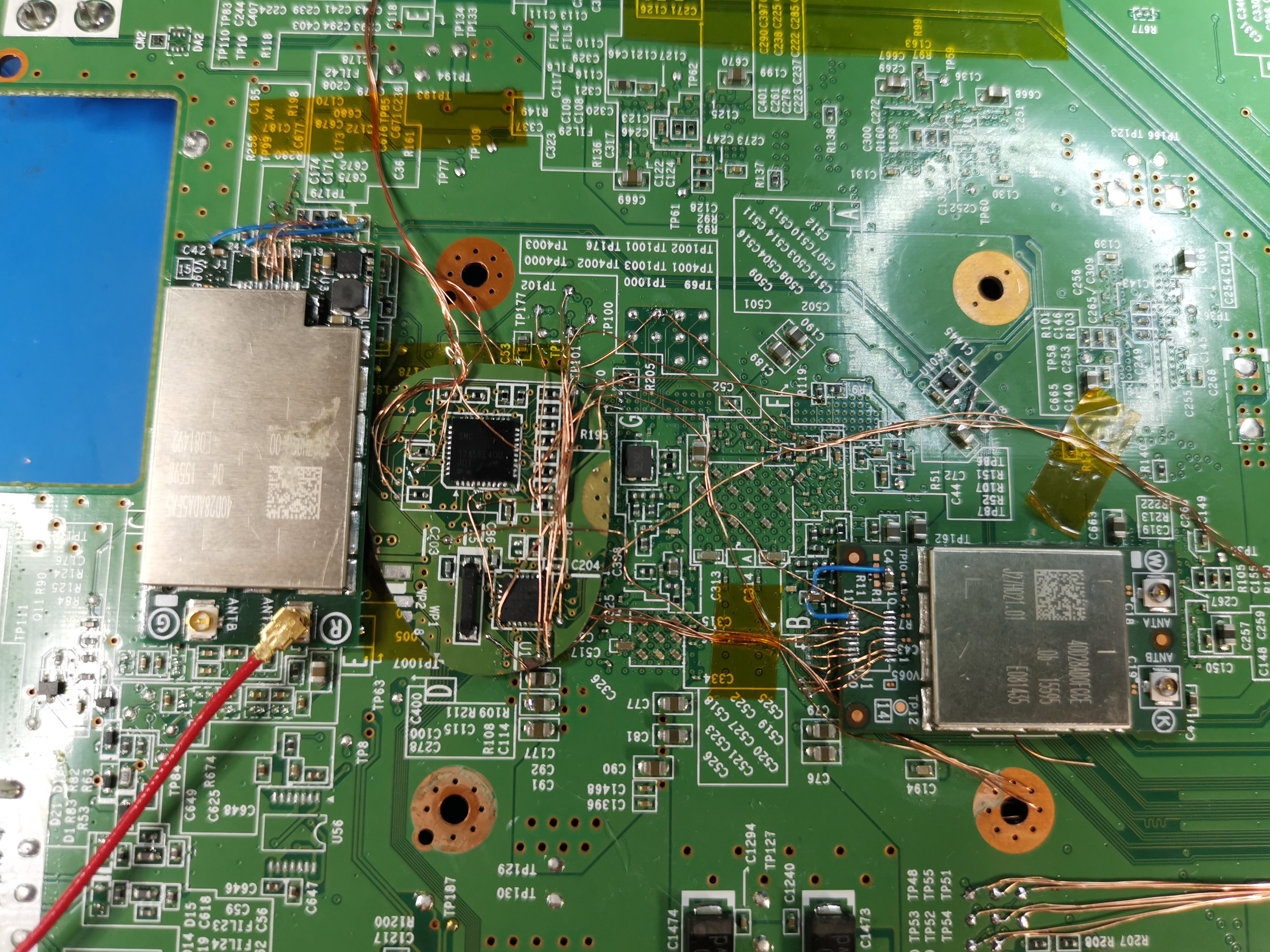
Here's the mobo wiring. I bypassed the series resistors for the 2.4GHz module since those will be trimmed off.
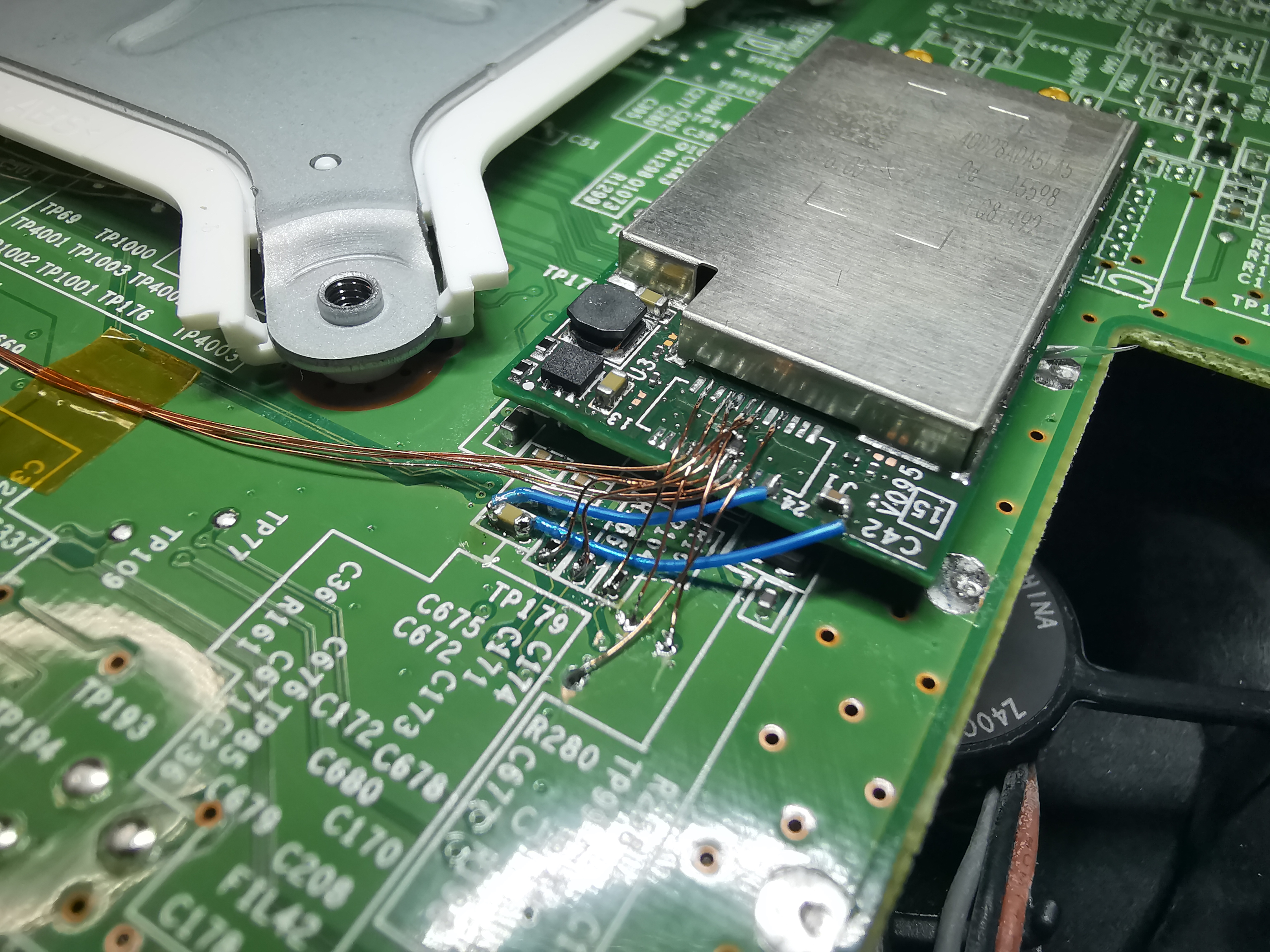
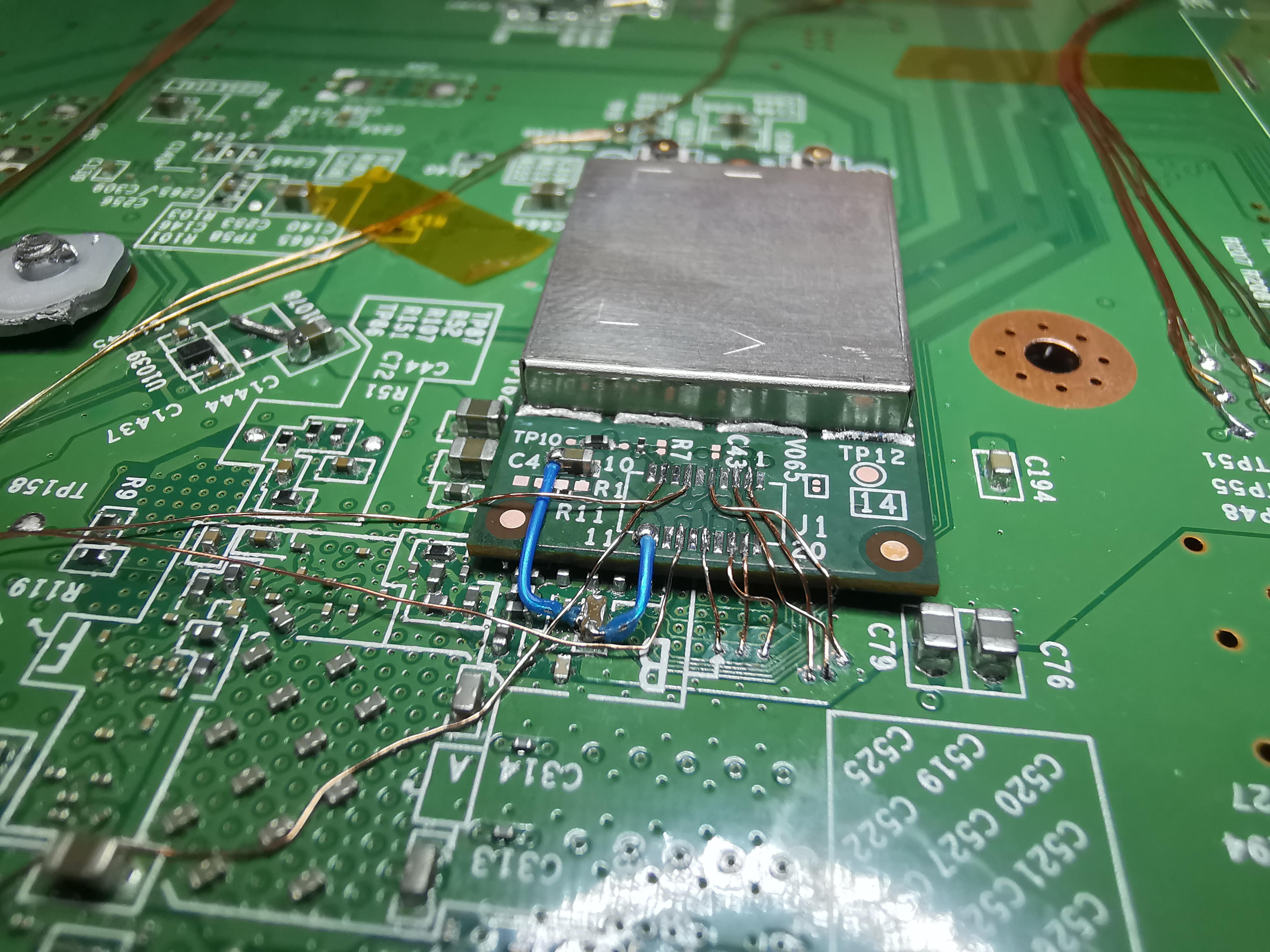

GamePad module works! And the WiFi module works too! (The console will freeze on the settings menu/not boot games if WiFi isn't working.)
Thanks to @Redherring32 for sending me a Japanese GamePad so I can quit using drc-sim!
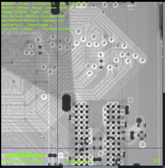
In other news, I took a WUP-50 to work and had it X-rayed:
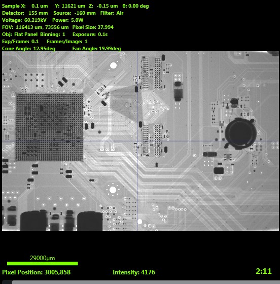
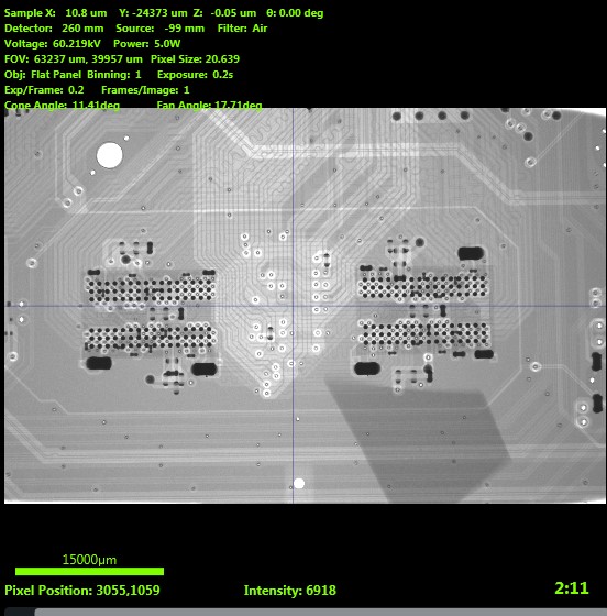
Why? Well, I've had my fill of motherboard sanding for a while and I don't want to sand+scan all 6 layers of the WUP-50 like I did with the WUP-01.
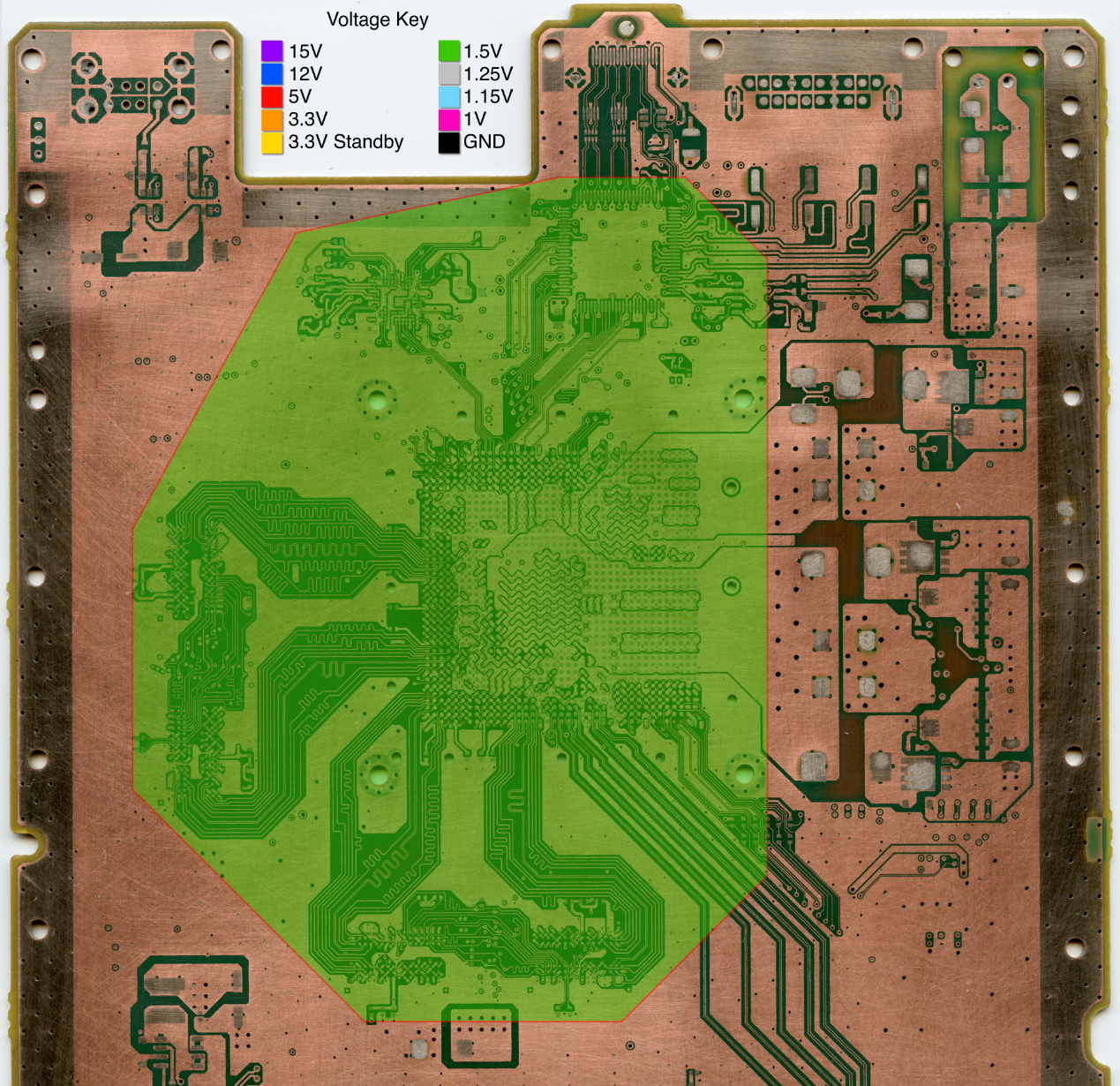
However, I still need to know how far out the DDR3 traces go so I don't sever them while trimming. These traces (vertical ones in the below pic) are on internal layers and define the outer trim boundary on 2 sides of the mobo.
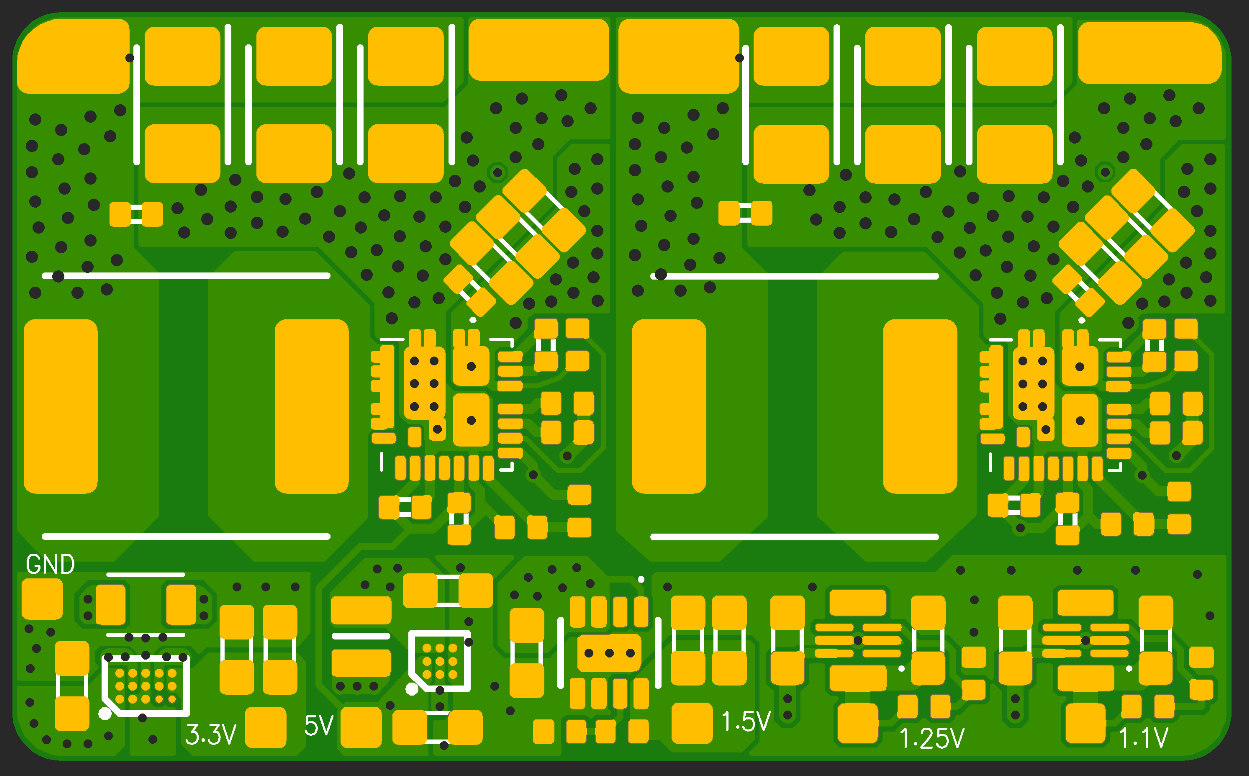
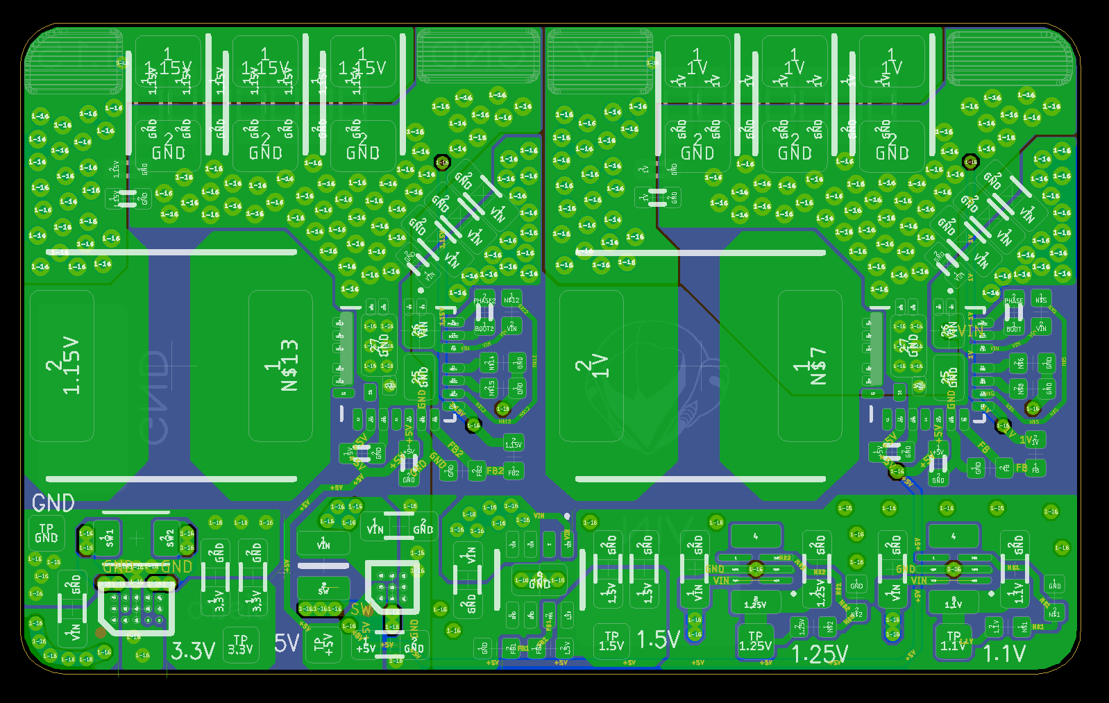
I also whipped up a revised 1v/1.15v regulator board for the SiC43X parts. Thankfully the inductors on the eval boards were super overkill. I was able to downsize to MPXV1D0840LR22 inductors which are 8x8x4mm. Pumping 15A through a board this small (37x16mm) scares me... so I went overboard with stitching vias and will be getting 2oz copper on all four layers.
Connectors wired up under the microscope. The GamePad module needs some deadbugged pullup/pulldown resistors.
Here's the mobo wiring. I bypassed the series resistors for the 2.4GHz module since those will be trimmed off.
GamePad module works! And the WiFi module works too! (The console will freeze on the settings menu/not boot games if WiFi isn't working.)
Thanks to @Redherring32 for sending me a Japanese GamePad so I can quit using drc-sim!
In other news, I took a WUP-50 to work and had it X-rayed:
Why? Well, I've had my fill of motherboard sanding for a while and I don't want to sand+scan all 6 layers of the WUP-50 like I did with the WUP-01.
However, I still need to know how far out the DDR3 traces go so I don't sever them while trimming. These traces (vertical ones in the below pic) are on internal layers and define the outer trim boundary on 2 sides of the mobo.
I also whipped up a revised 1v/1.15v regulator board for the SiC43X parts. Thankfully the inductors on the eval boards were super overkill. I was able to downsize to MPXV1D0840LR22 inductors which are 8x8x4mm. Pumping 15A through a board this small (37x16mm) scares me... so I went overboard with stitching vias and will be getting 2oz copper on all four layers.
Last edited:
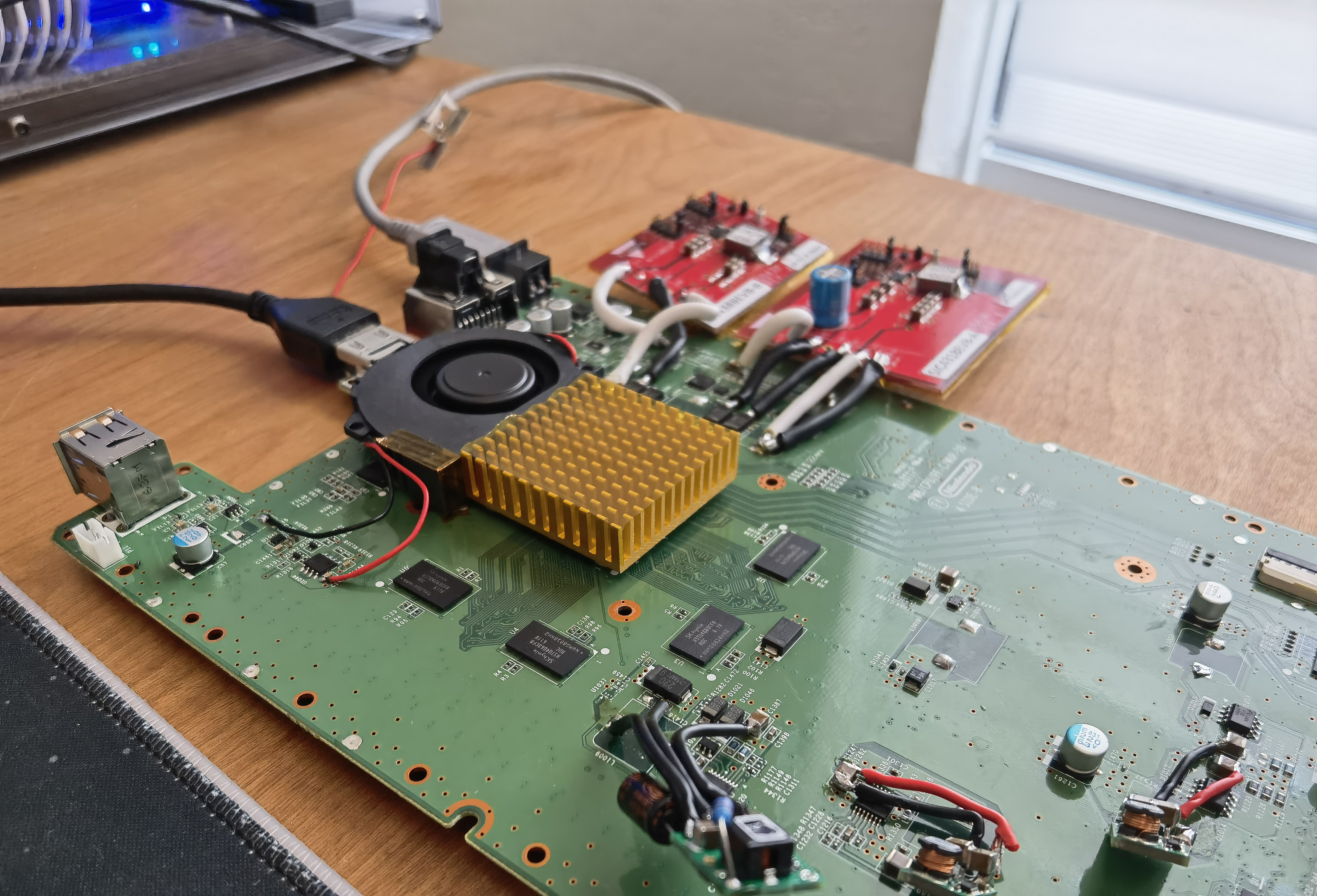
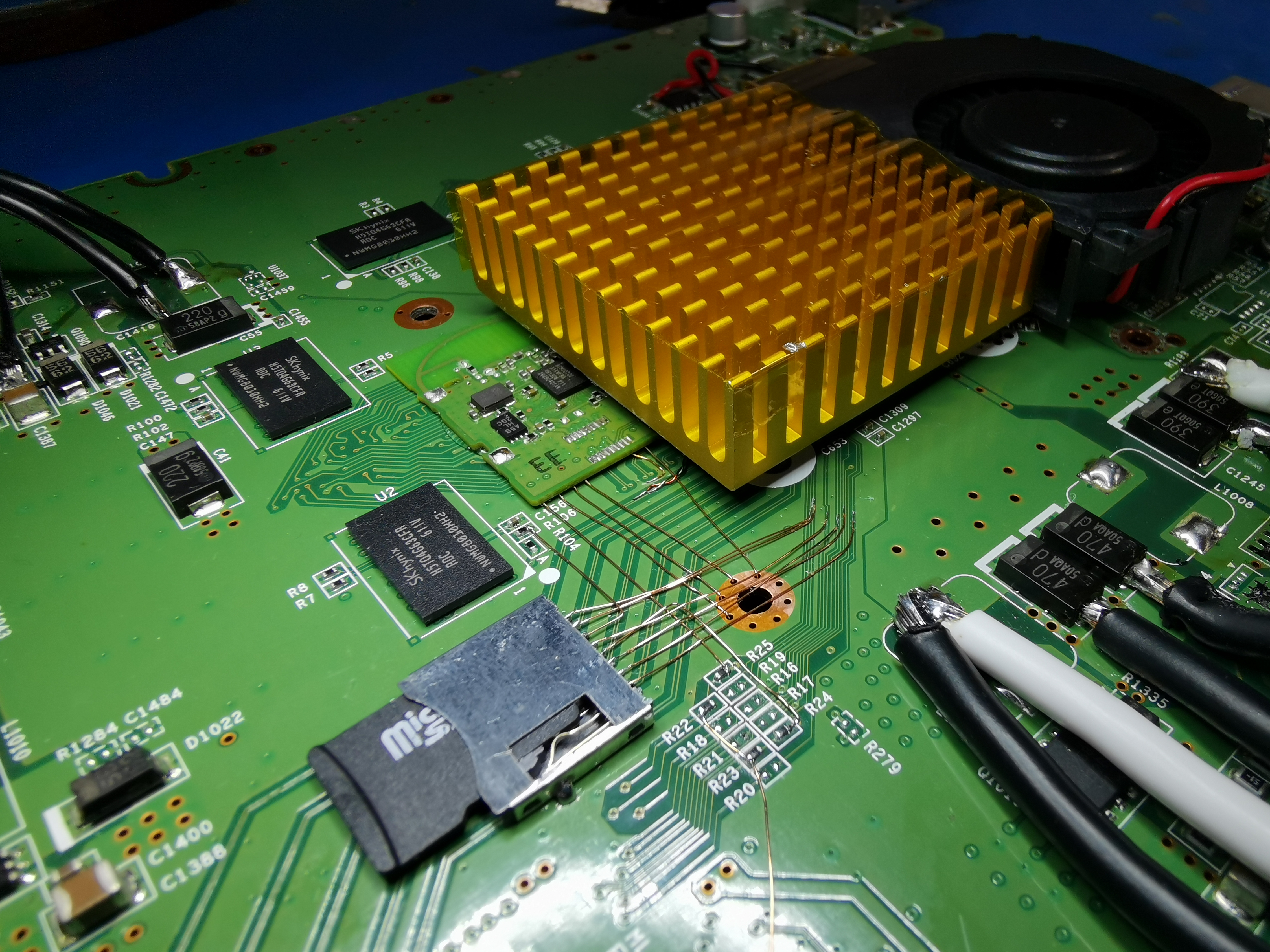
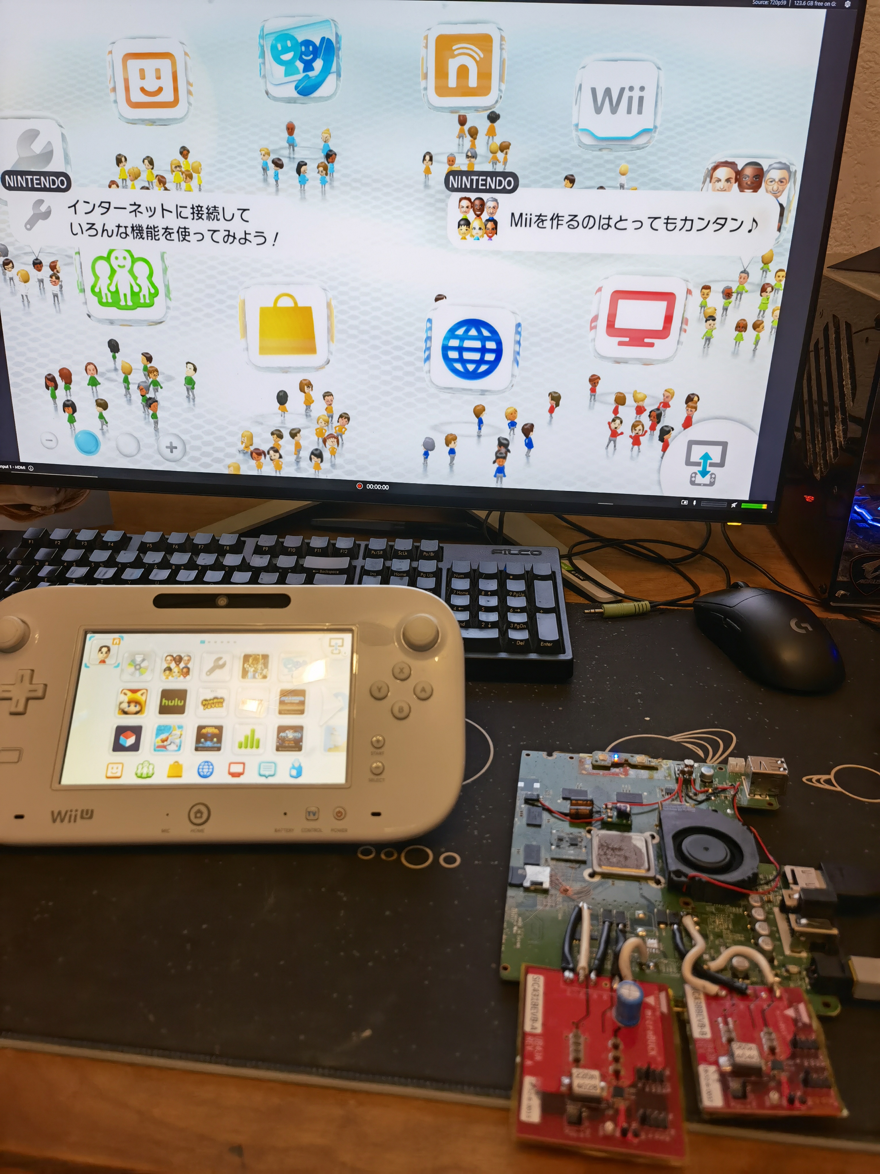
Chill weekend, but I still got some Wii U work done!
I tested a new cooling setup using this fan and a 45x45x10mm heatsink. It works well and is more than enough cooling for the WUP-50. At 3.3V the fan is pretty quiet, but the mobo gets a tad warm. At 5V the fan is loud but things stay much cooler. I think PWM'd 5V and a 50x50mm heatsink would be ideal.
After undoing an accidental 15V-to-GND mod caused by a cracked MLCC (don't ask) I got to work relocating the Bluetooth module. Once again, I'm following in @Crazzyleprechaun's footsteps. He noticed the other day that some Wii U BT modules have test pads not unlike those found on Wii BT modules. They're pretty rare compared to the naked modules, sadly. Here's a pinout for those interested. I'll share pinouts/diagrams like this for all the wireless modules once I wrap up trim development.
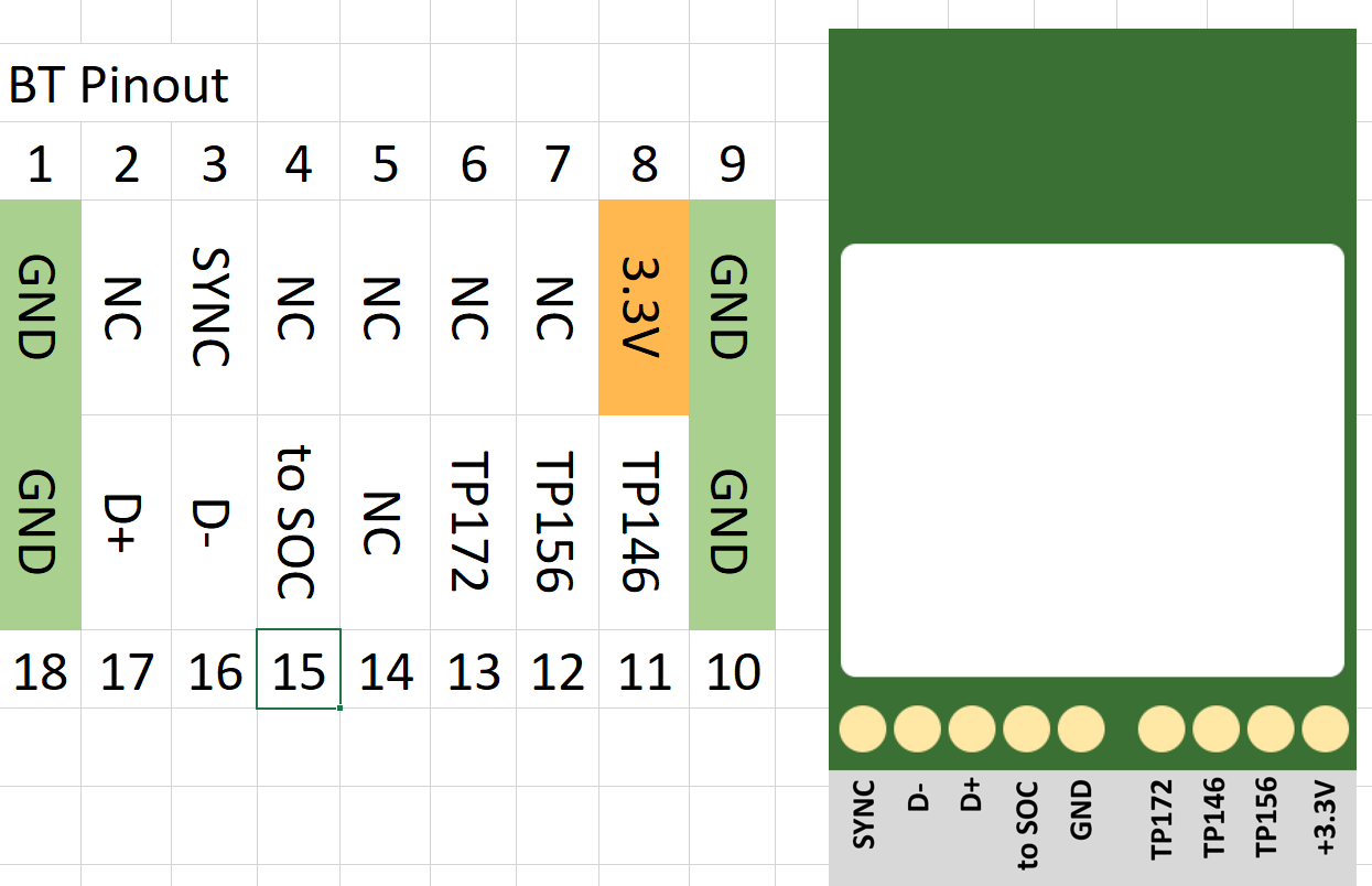
Crazzy's tests indicate some of the signals going to the processor and SMC aren't required. It's likely one is an active-low reset, and at least one is an interrupt from the module to wake the processor from standby mode. I wired up everything anyway, just to be safe.
I removed the can to get the module low-profile enough to sit under the heatsink. The GamePad doesn't use the BT module, so it's only really needed for booting Wii games and so the console doesn't freeze/freak out in certain situations.
Next up is the SD card. This is actually a major pain point for Wii U portablizing. Since both de_Fuse and Tiramisu/Aroma require an SD card to function, relocating it is mandatory. (From my limited understanding, homebrew devs don't have low-level USB drivers, so making that stuff run from USB isn't doable yet.)
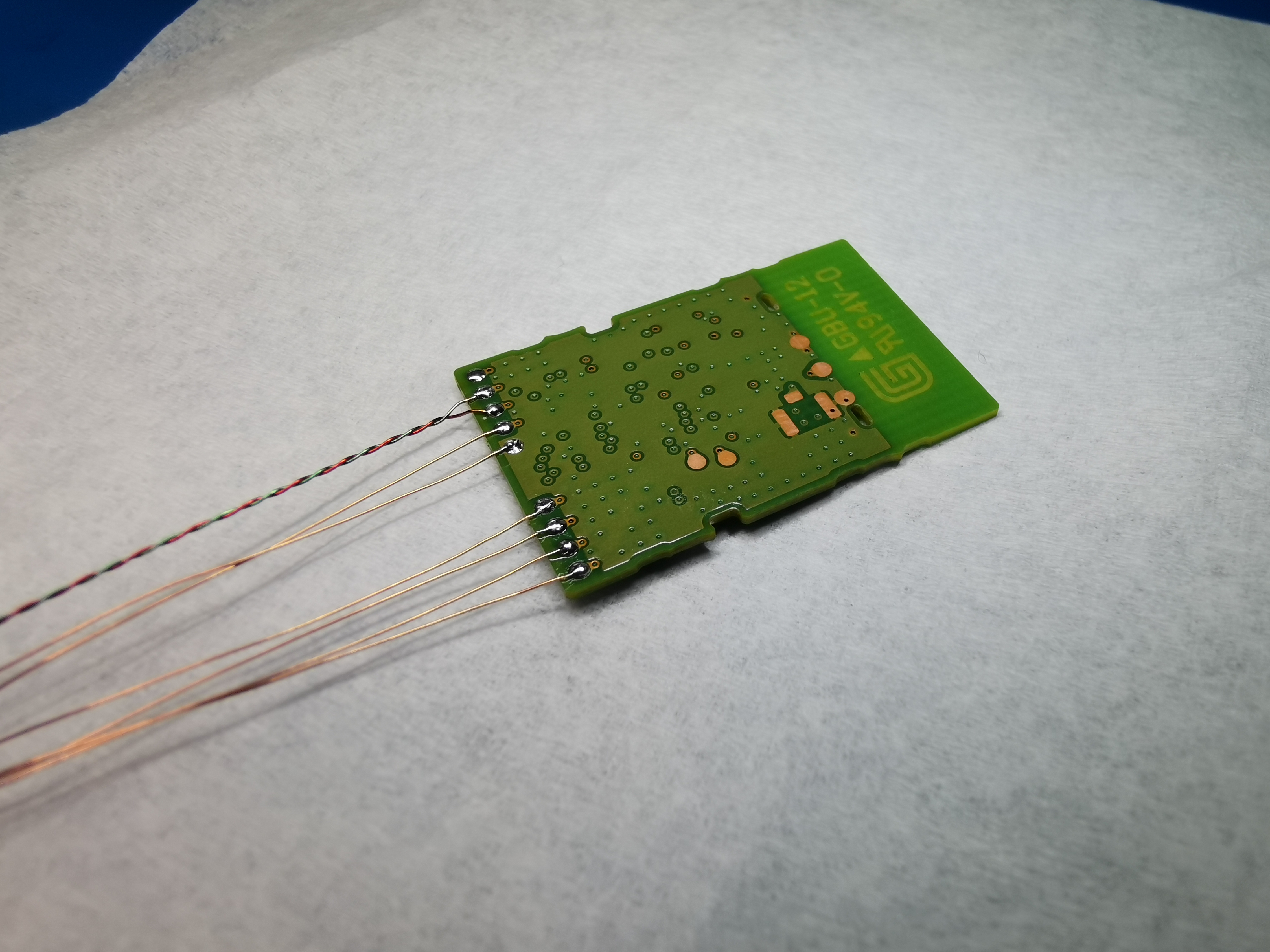
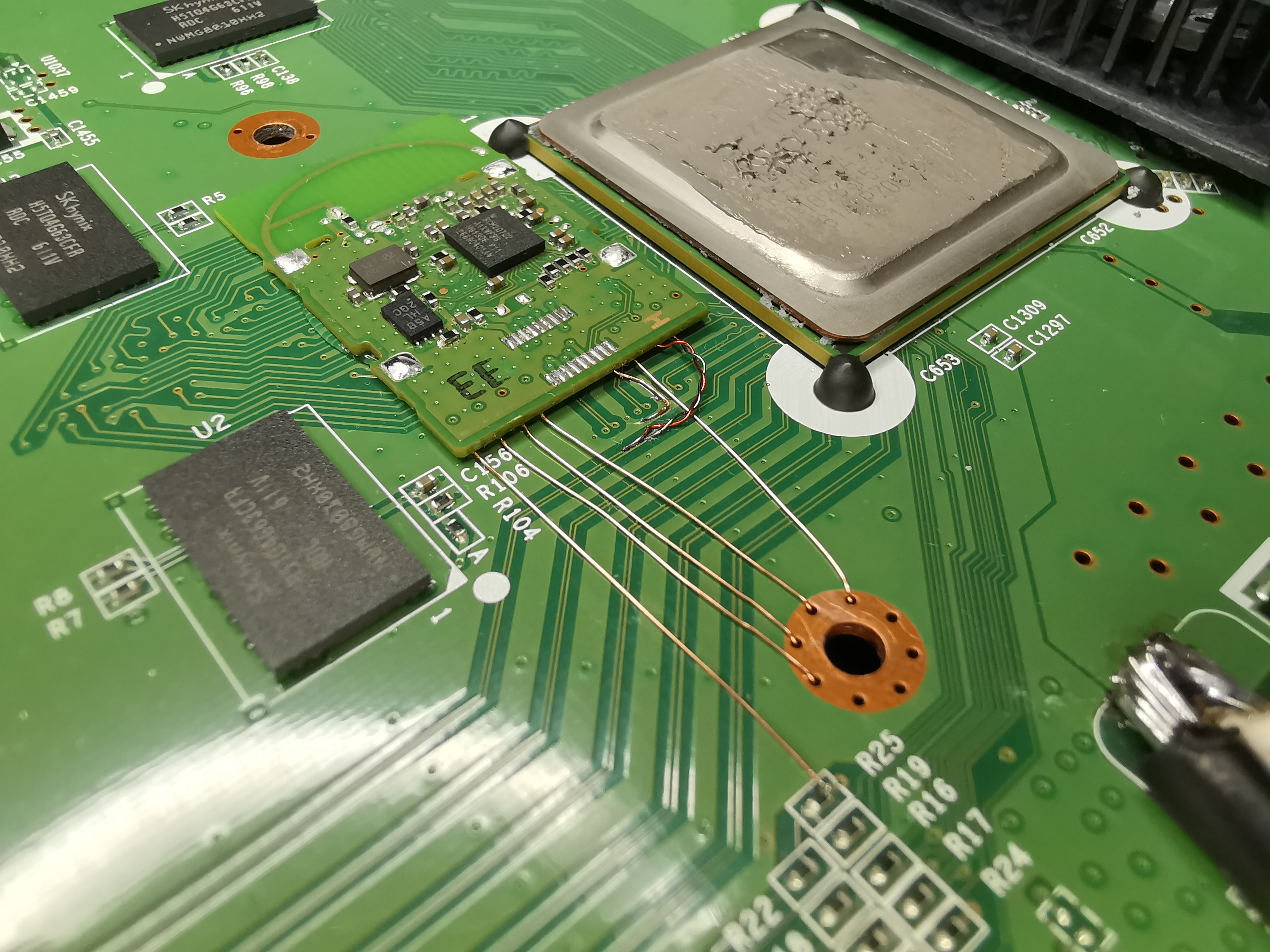
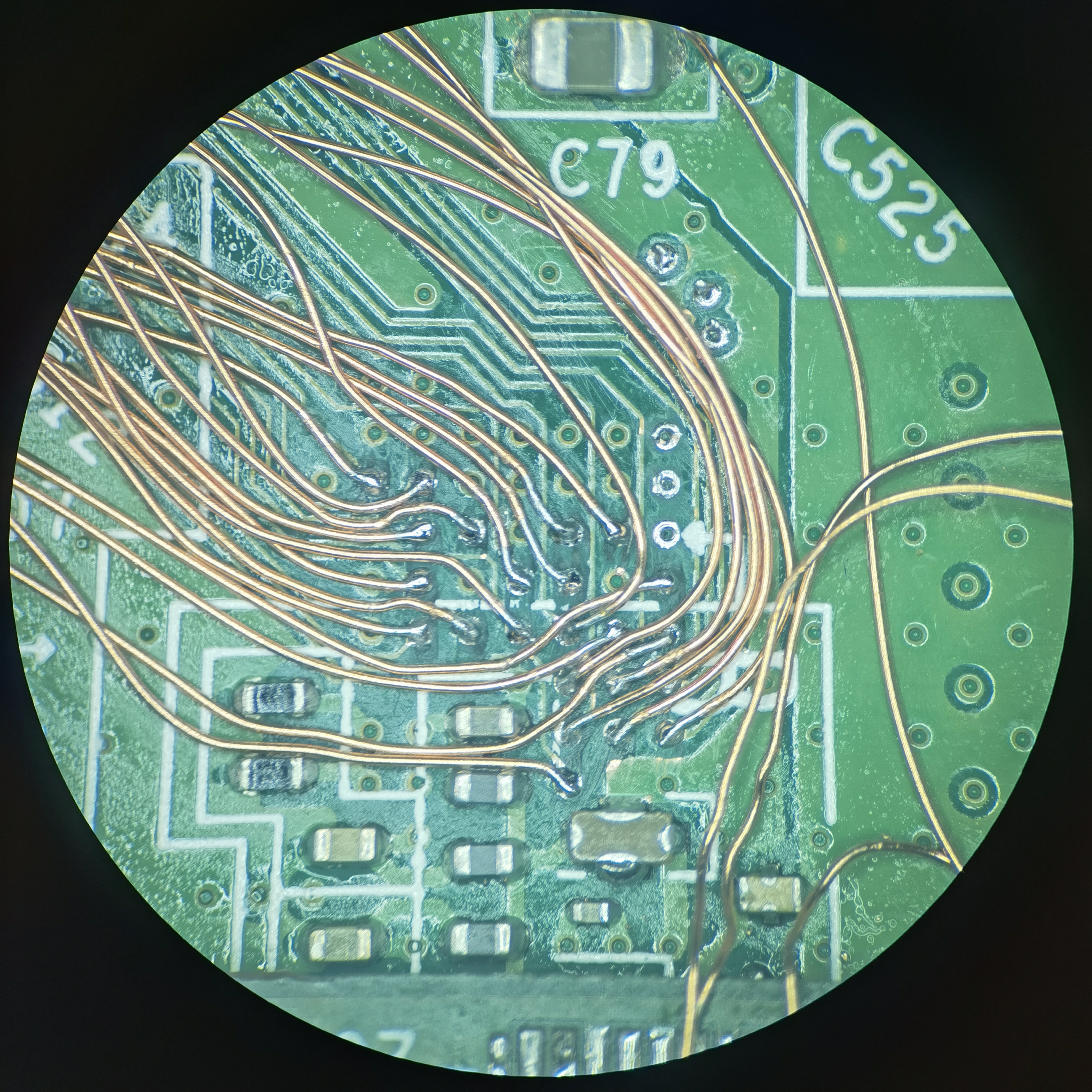
The SDIO traces run from the SD card to series resistors near the SOC. On the WUP-01, these resistors are in a mediocre but acceptable position, mostly within the theoretical trim boundaries:
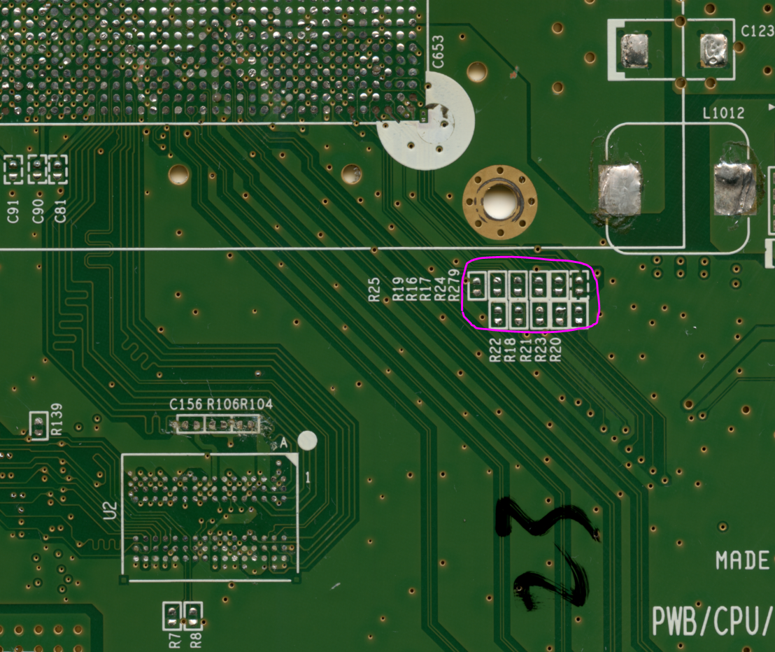
But on the WUP-50, these resistors are not in a good spot... They're way off to the side. Leaving them intact would add a full centimeter to the trimmed motherboard, which is not OK in my opinion. Instead, I soldered directly to the SDIO traces, bypassing the series resistors entirely:
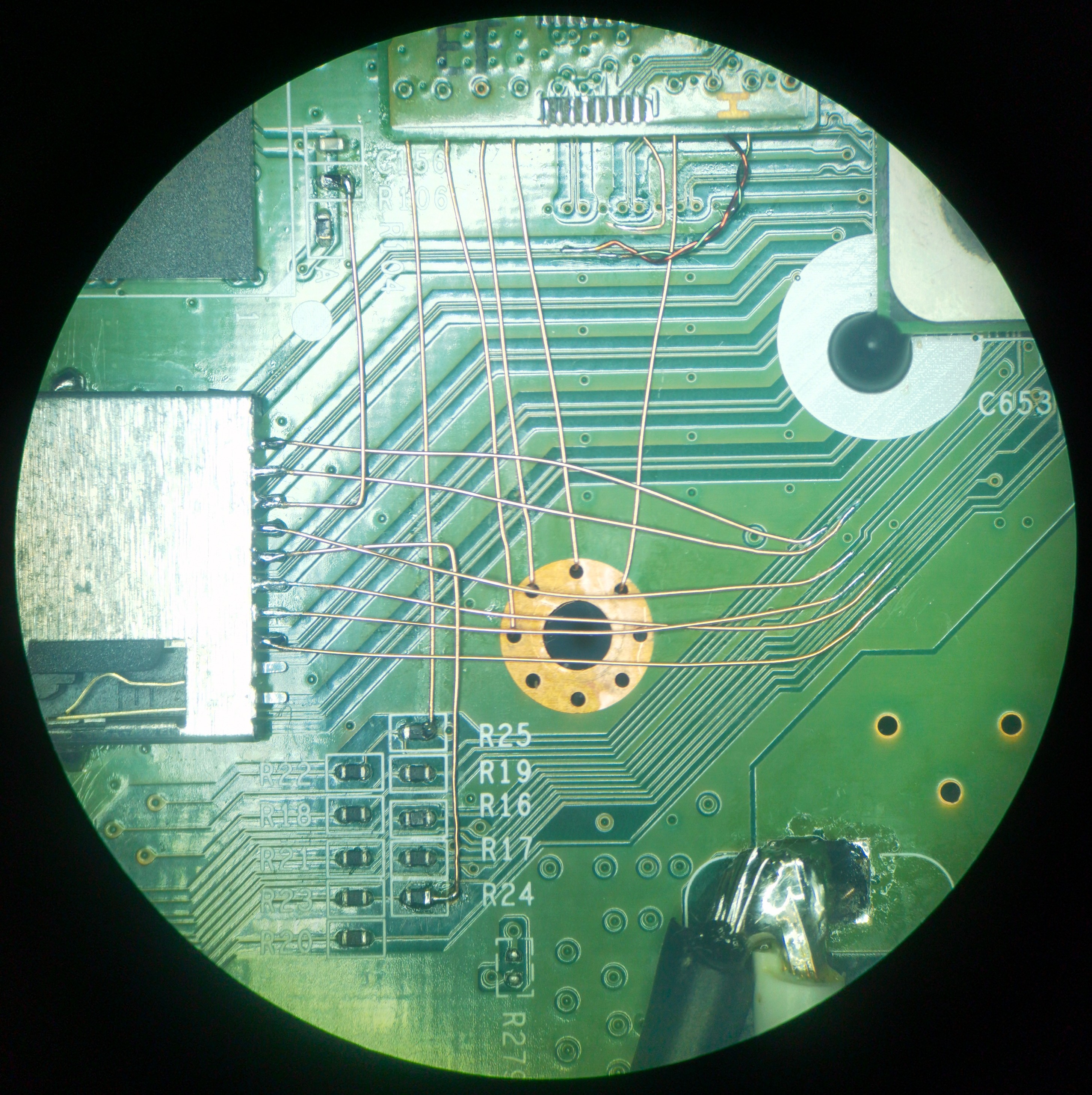
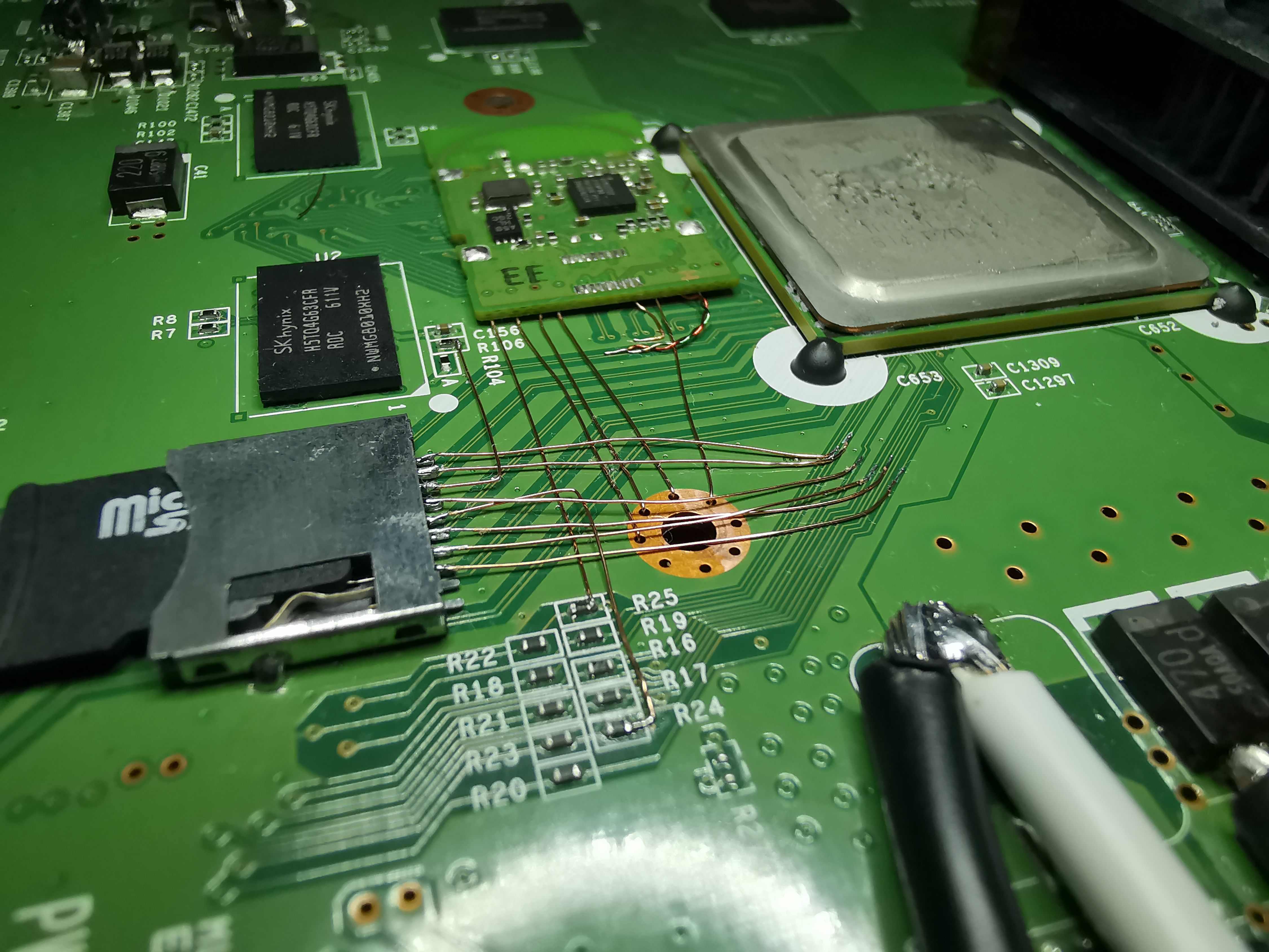
The Wii U won't mount the SD card if you don't short two card detect pins to GND, which I forgot to do initially. Also, I was getting Error 150-3030 until I desoldered the SDIO series resistors. Maybe the original traces running back to the full-size SD slot were acting as stubs and causing signal integrity issues?
After fixing those things:
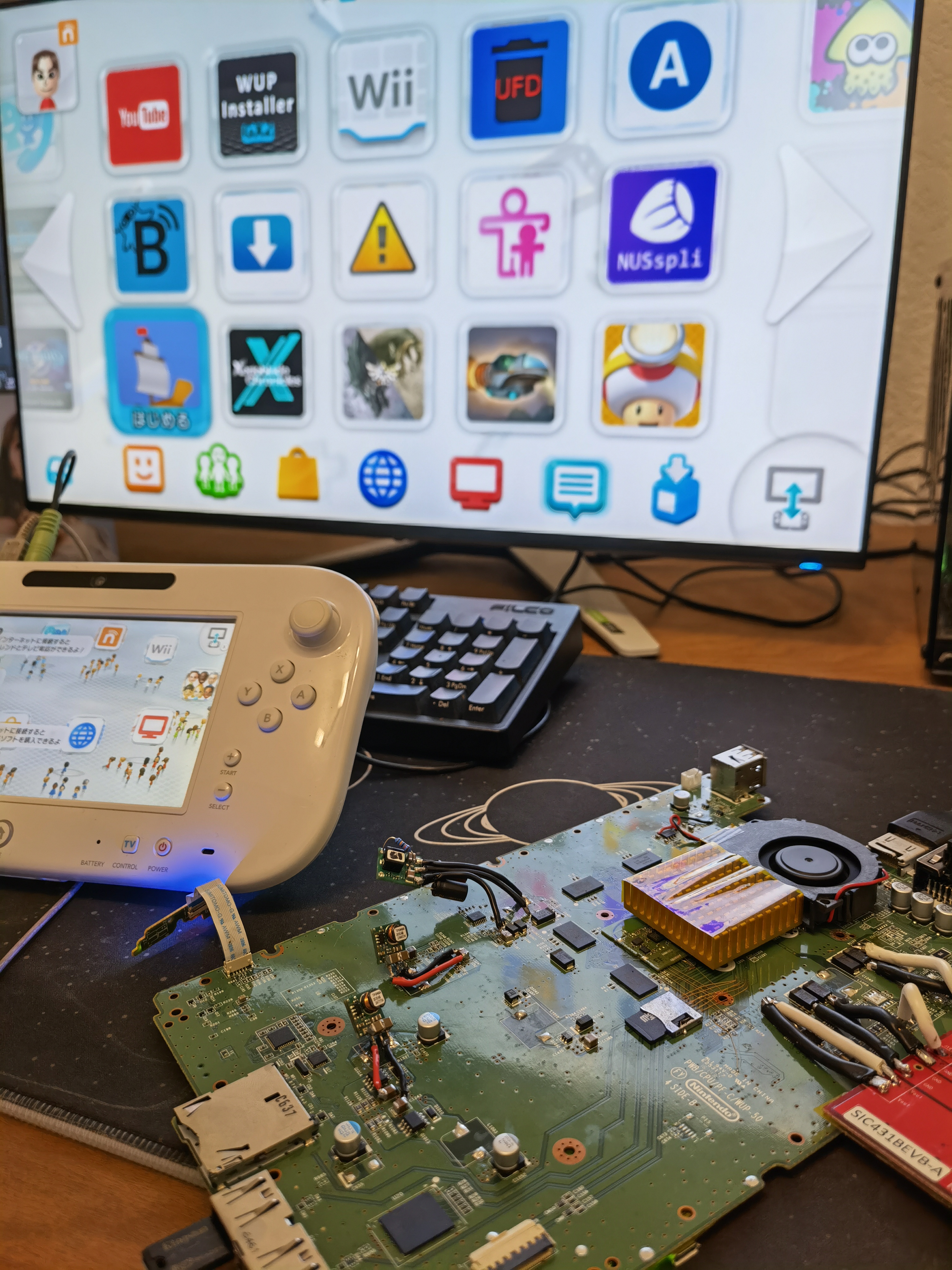
Success! de_Fuse is working, minute is booting from the microSD, and Aroma is displaying homebrew on the main menu.
Whether my hand-wiring (with parallel and overlapping wires, yuck!) will hold up during SDCafiine or other SD-intensive operations is unclear.
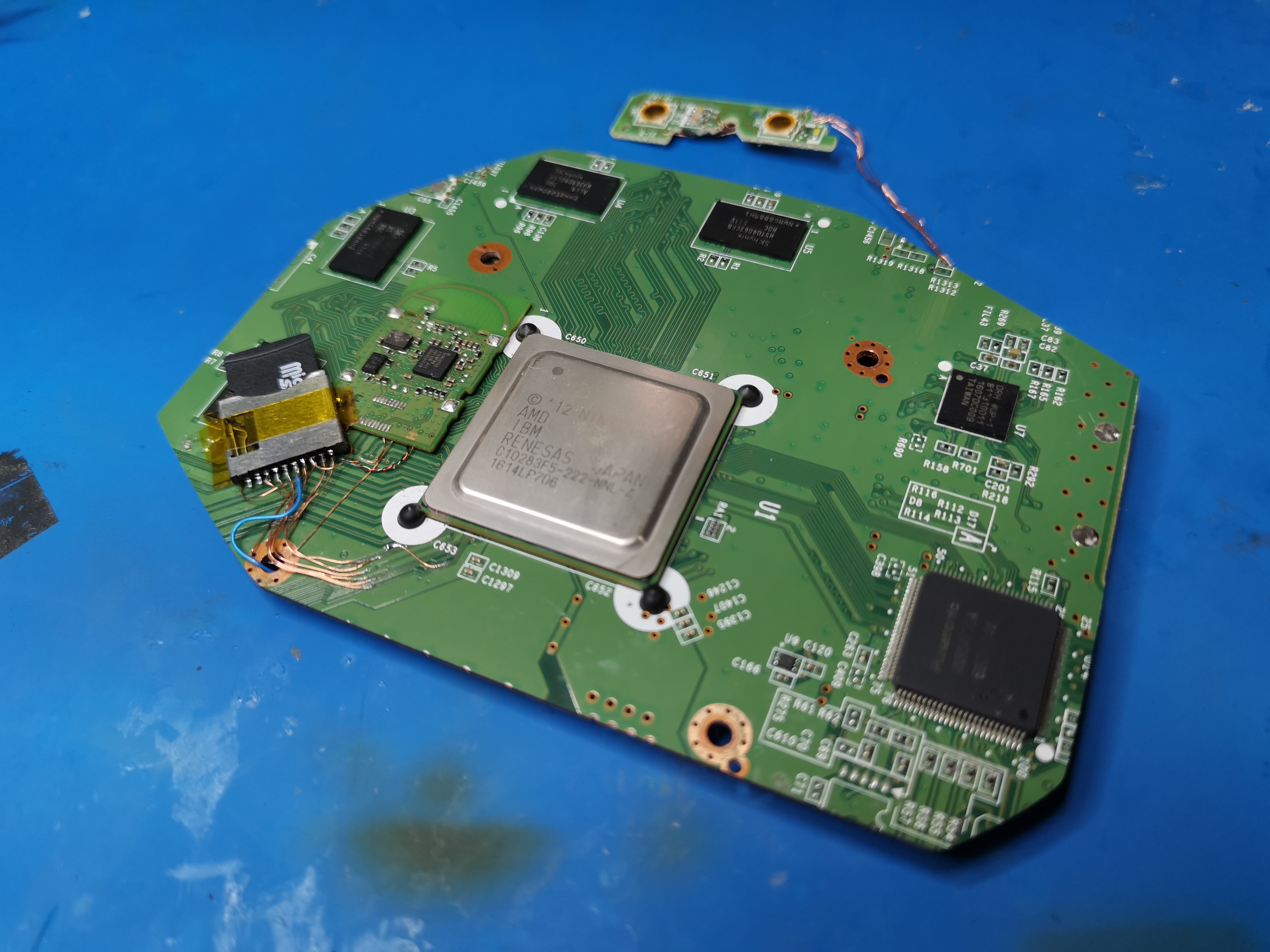
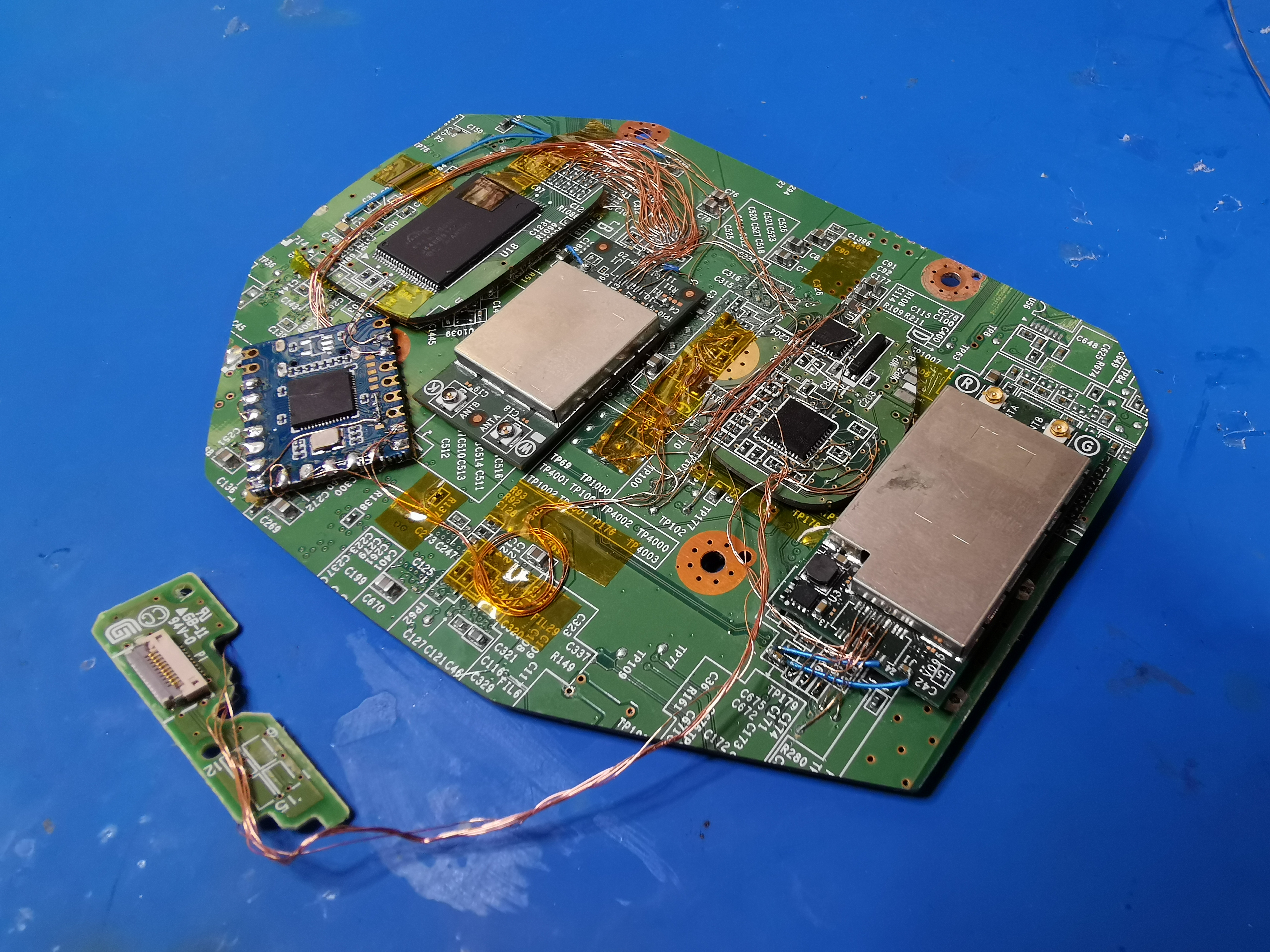
Now the only things left to relocate are the SMC+RTC and the NANDs! Here are some full mobo pics for posterity.
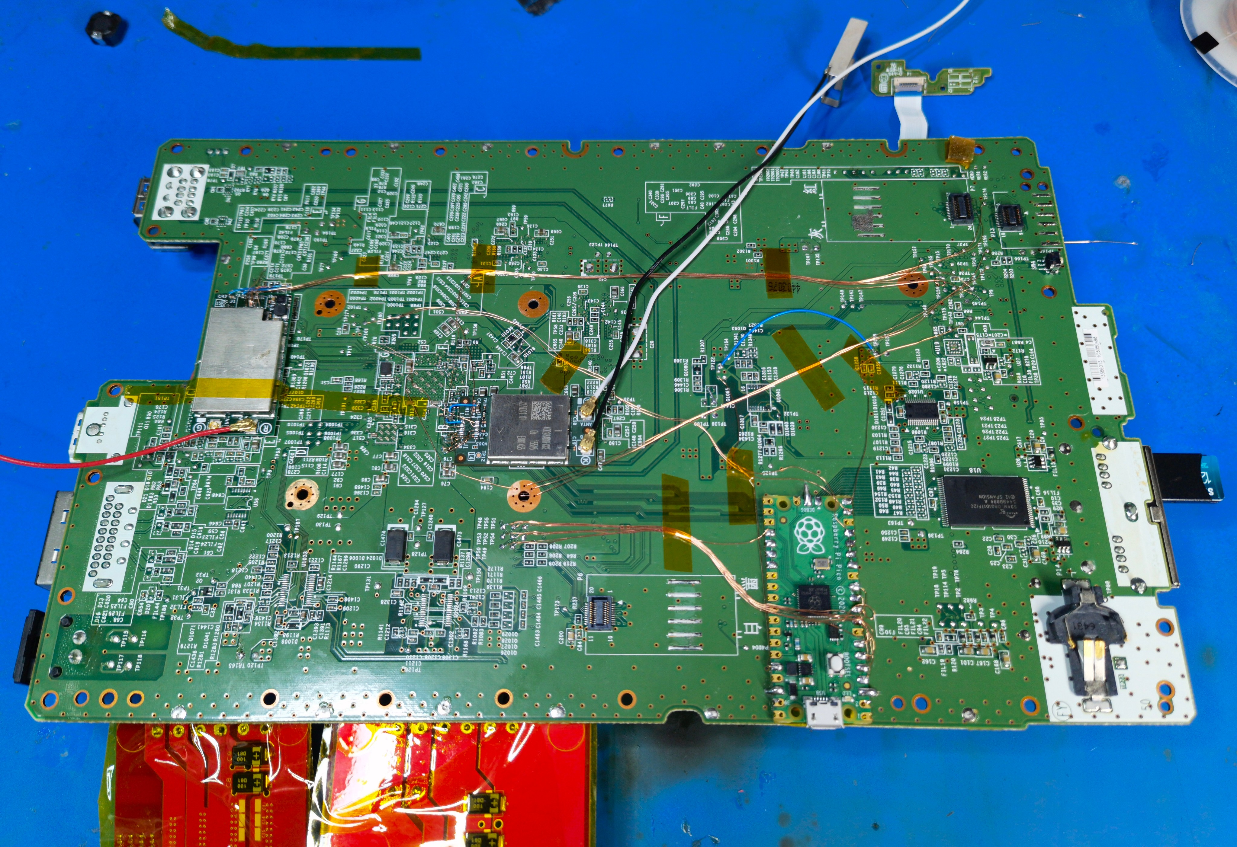
Very happy with how clean I've managed to keep everything so far. But I'm gonna have to remove the 2.4GHz module to access the NAND/eMMC vias... oh well.
I tested a new cooling setup using this fan and a 45x45x10mm heatsink. It works well and is more than enough cooling for the WUP-50. At 3.3V the fan is pretty quiet, but the mobo gets a tad warm. At 5V the fan is loud but things stay much cooler. I think PWM'd 5V and a 50x50mm heatsink would be ideal.
After undoing an accidental 15V-to-GND mod caused by a cracked MLCC (don't ask
) I got to work relocating the Bluetooth module. Once again, I'm following in @Crazzyleprechaun's footsteps. He noticed the other day that some Wii U BT modules have test pads not unlike those found on Wii BT modules. They're pretty rare compared to the naked modules, sadly. Here's a pinout for those interested. I'll share pinouts/diagrams like this for all the wireless modules once I wrap up trim development.Crazzy's tests indicate some of the signals going to the processor and SMC aren't required. It's likely one is an active-low reset, and at least one is an interrupt from the module to wake the processor from standby mode. I wired up everything anyway, just to be safe.
I removed the can to get the module low-profile enough to sit under the heatsink. The GamePad doesn't use the BT module, so it's only really needed for booting Wii games and so the console doesn't freeze/freak out in certain situations.
Next up is the SD card. This is actually a major pain point for Wii U portablizing. Since both de_Fuse and Tiramisu/Aroma require an SD card to function, relocating it is mandatory. (From my limited understanding, homebrew devs don't have low-level USB drivers, so making that stuff run from USB isn't doable yet.)
The SDIO traces run from the SD card to series resistors near the SOC. On the WUP-01, these resistors are in a mediocre but acceptable position, mostly within the theoretical trim boundaries:
But on the WUP-50, these resistors are not in a good spot... They're way off to the side. Leaving them intact would add a full centimeter to the trimmed motherboard, which is not OK in my opinion. Instead, I soldered directly to the SDIO traces, bypassing the series resistors entirely:
The Wii U won't mount the SD card if you don't short two card detect pins to GND, which I forgot to do initially. Also, I was getting Error 150-3030 until I desoldered the SDIO series resistors. Maybe the original traces running back to the full-size SD slot were acting as stubs and causing signal integrity issues?
After fixing those things:
Success! de_Fuse is working, minute is booting from the microSD, and Aroma is displaying homebrew on the main menu.
Whether my hand-wiring (with parallel and overlapping wires, yuck!) will hold up during SDCafiine or other SD-intensive operations is unclear.
Now the only things left to relocate are the SMC+RTC and the NANDs! Here are some full mobo pics for posterity.
Very happy with how clean I've managed to keep everything so far. But I'm gonna have to remove the 2.4GHz module to access the NAND/eMMC vias... oh well.
Attachments
-
 1.2 MB Views: 76
Last edited:
I took last week off to work on a different project, but I'm back in the Wii U fray now. Long update incoming!
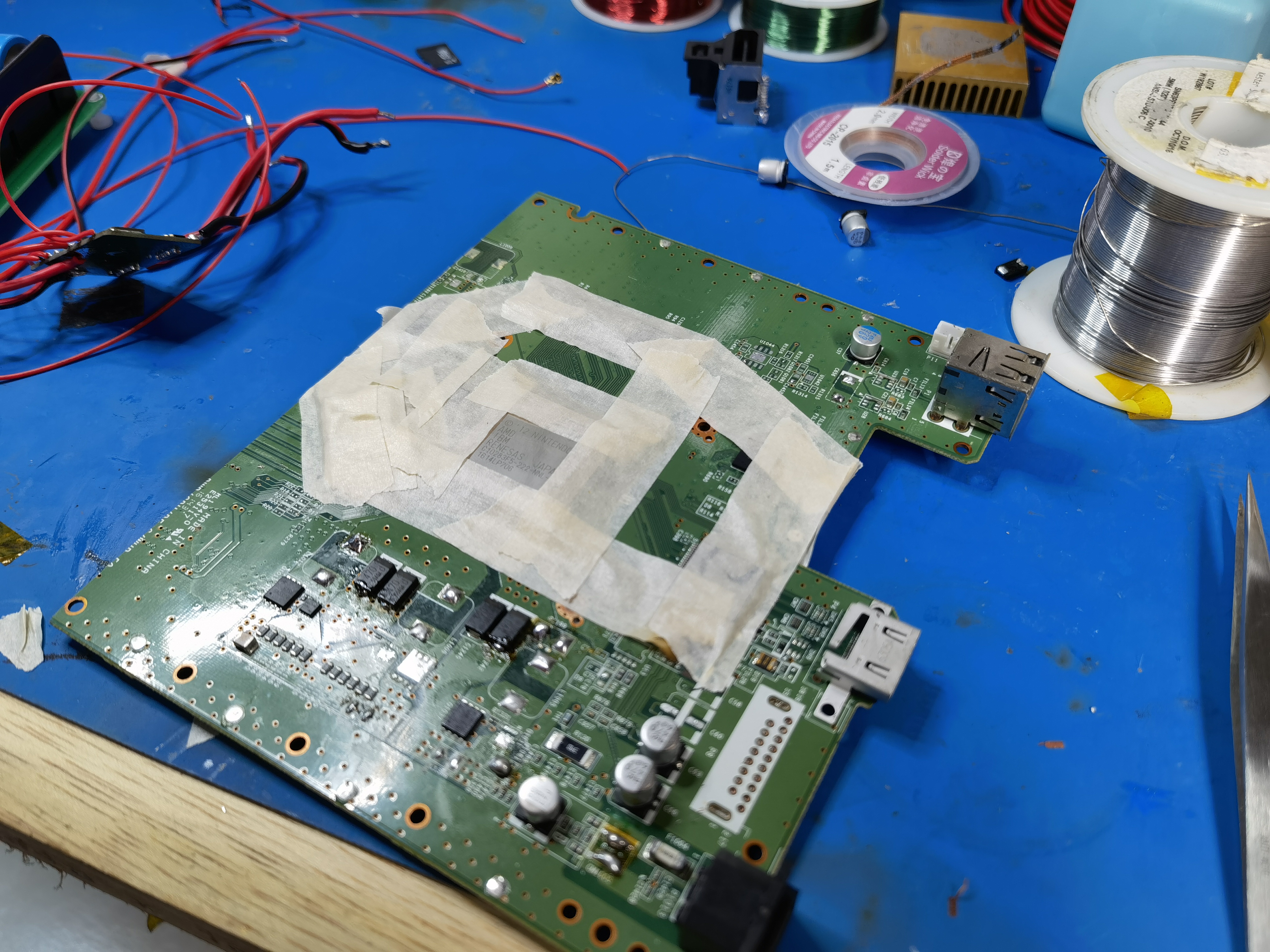
I cut out the SMC and RTC from a WUP-01 motherboard. I was so excited, I forgot to take microscope photos of the bare daughterboard! But here are some pics of the relocation.

Because I didn't rewire the SMC pins that normally enable the rear USB port protectors, I had to remove them and jumper 5V across the pads.
Despite taking shortcuts like this, the SMC and RTC still required an annoying amount of wiring. I2C for the SMC, EXI for the RTC, power button, R/B/Y LEDs, and all the GPIOs for the wireless modules. But the relocation worked!
After this, I spent some time cleaning up and consolidating the wiring and regs in preparation for a preliminary trim.
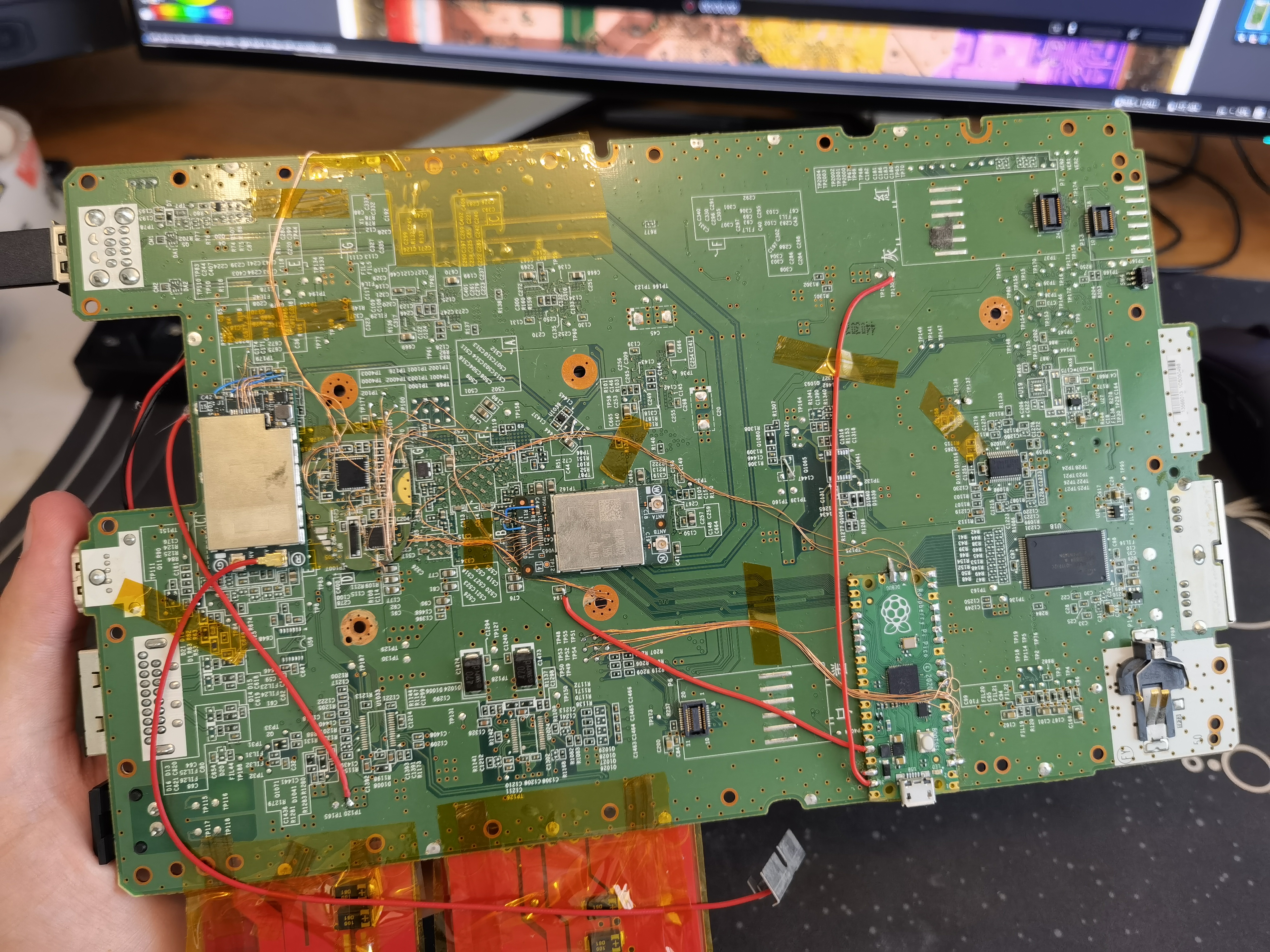
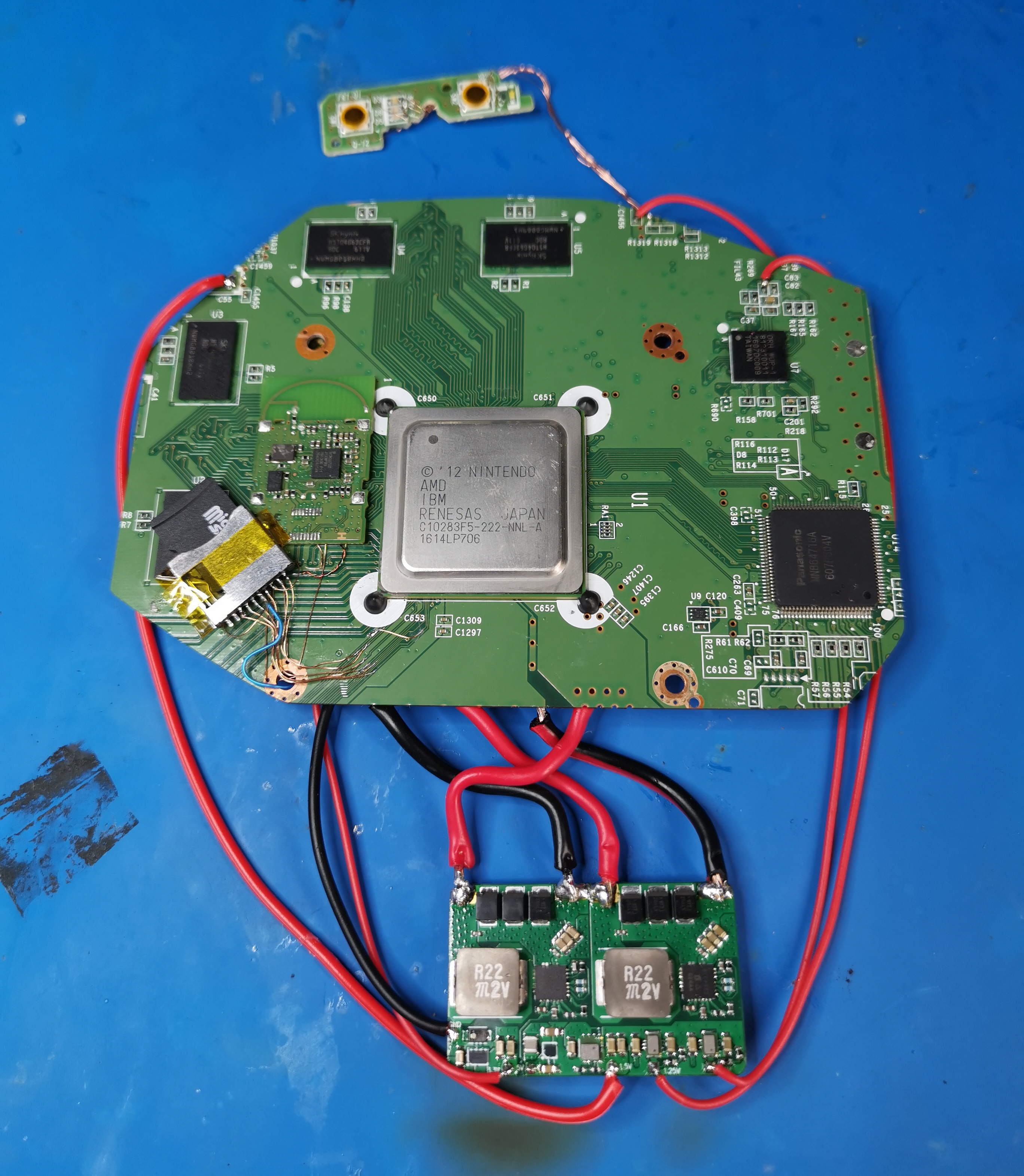
I was able to run the 3.3V line from the Pico's onboard regulator, which was convenient. I also moved the Pico to beneath the SOC (not shown).
Next up was the flash memory. Since the eMMC and NAND are tied to the console, you can't use ones from a different motherboard without some dumping/reflashing shenanigans. In other words, the NAND daughterboard must be cut from the same motherboard. This is an irreversible step and must be done at the same time as a mobo trim, which is why I saved this relocation for last.
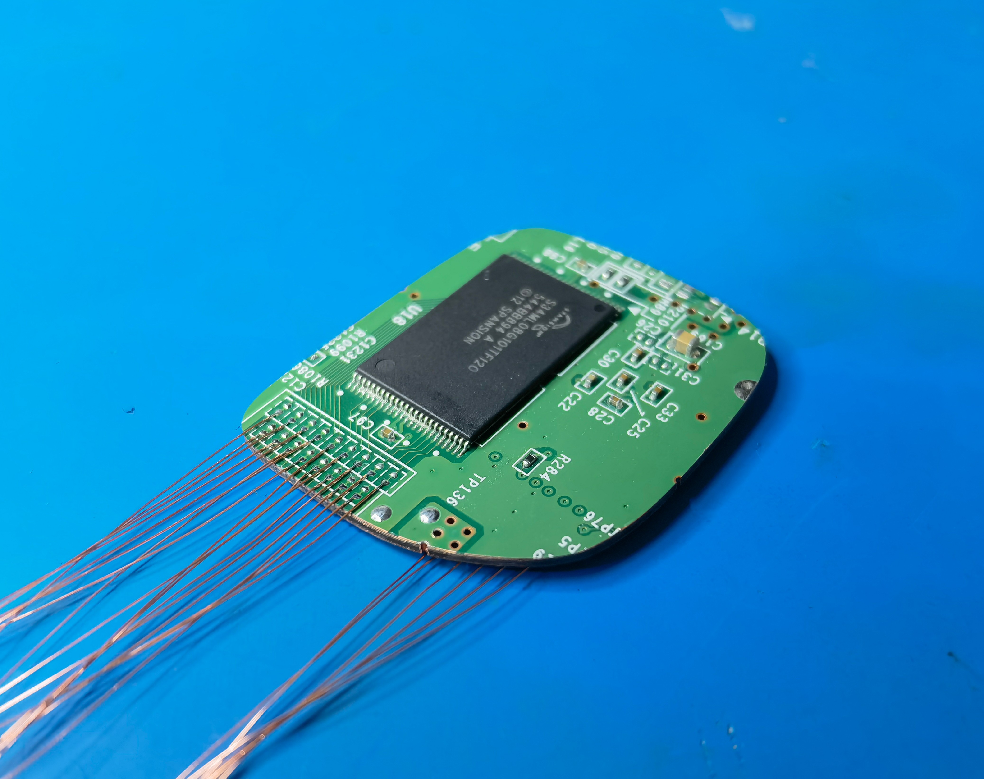
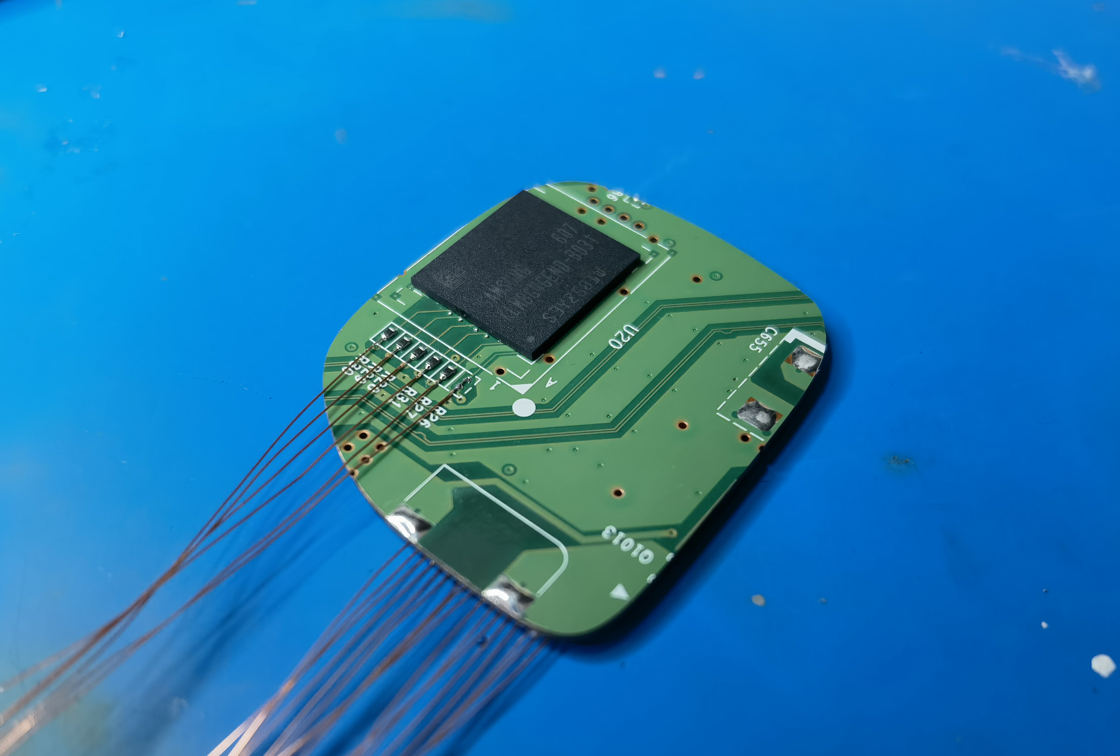
NAND/eMMC daughterboard...
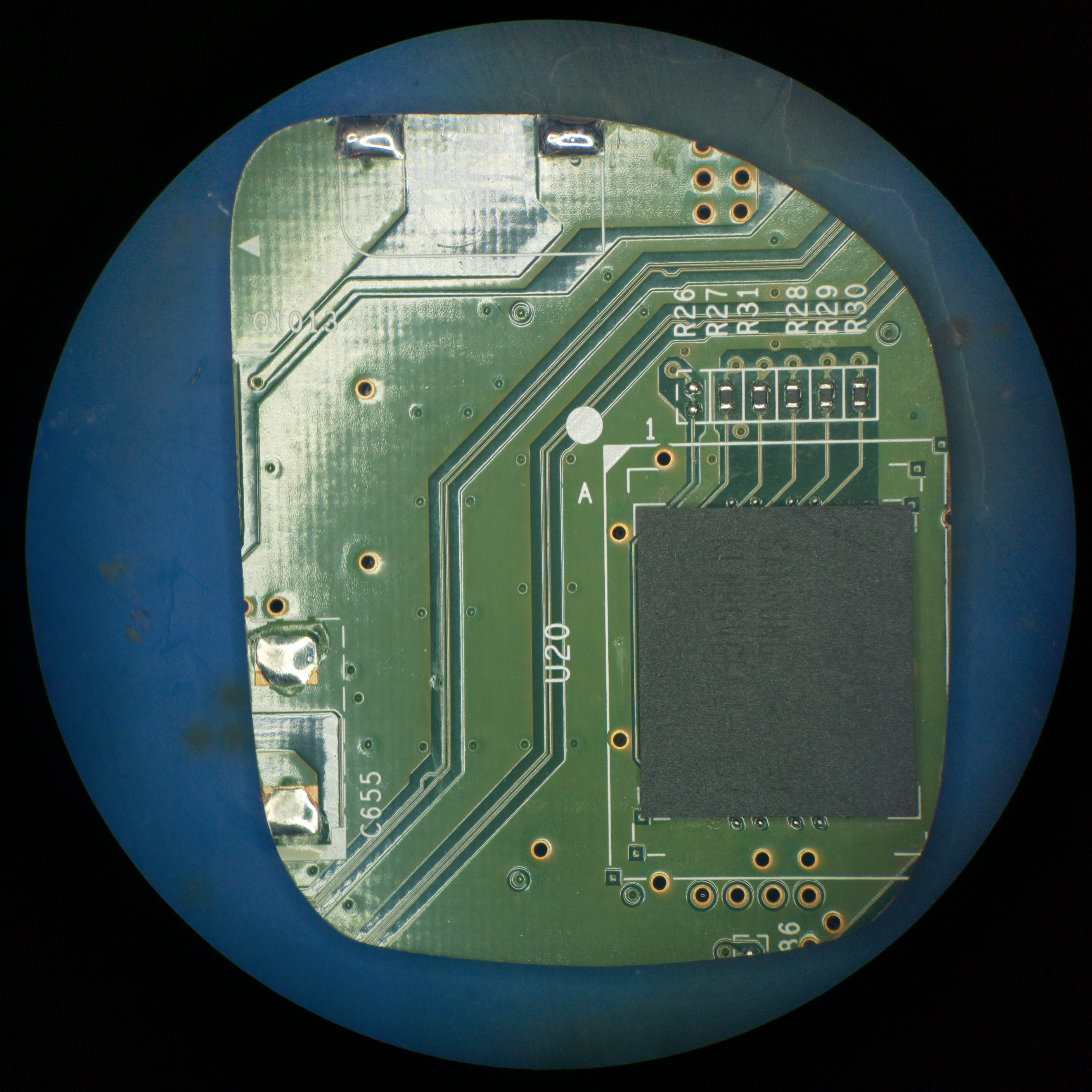
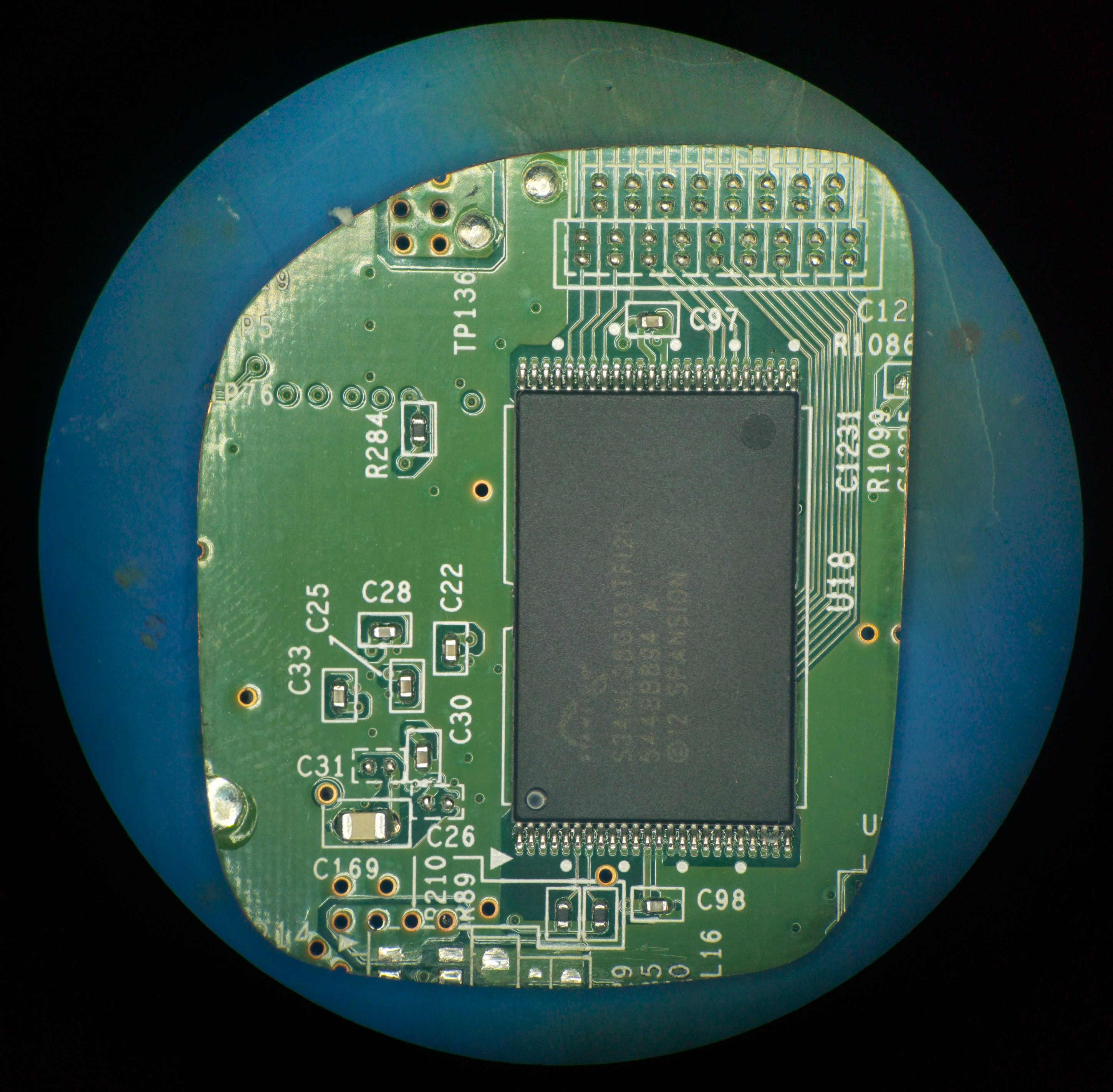
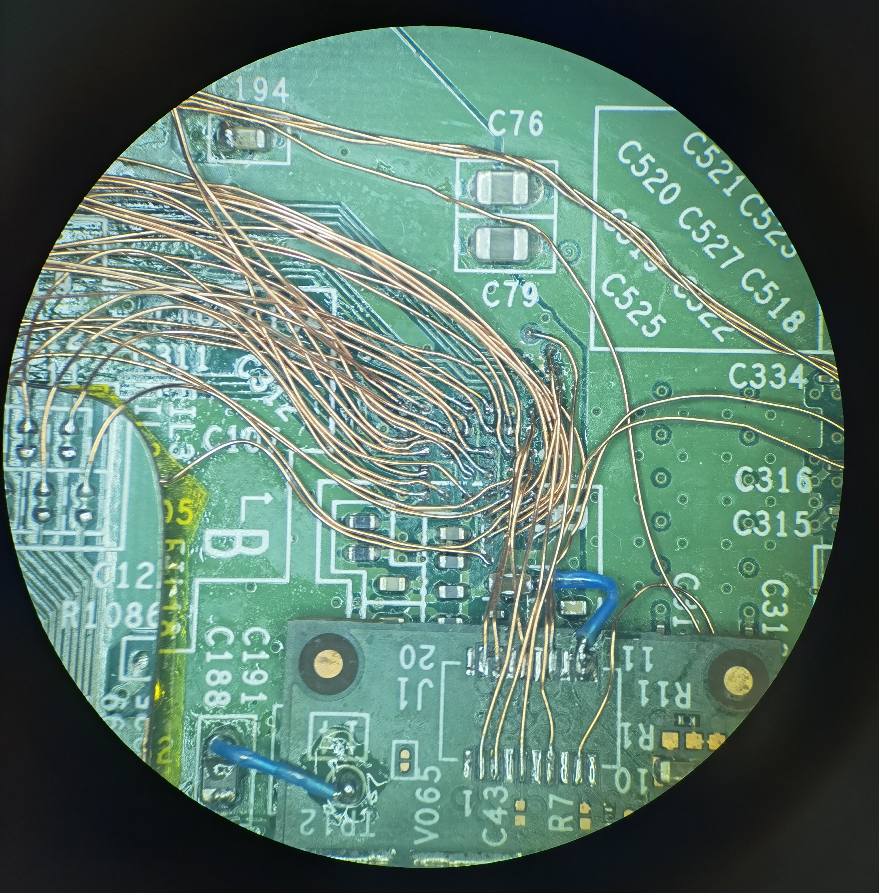
...and with wires attached. The eMMC uses 4-bit SDIO (6 wires) and the TSOP NAND uses the same ONFI type interface as the Wii NAND (17 wires).
Here's the trimmed Wii U motherboard after sanding. Keep in mind this is just a preliminary trim for testing purposes.")
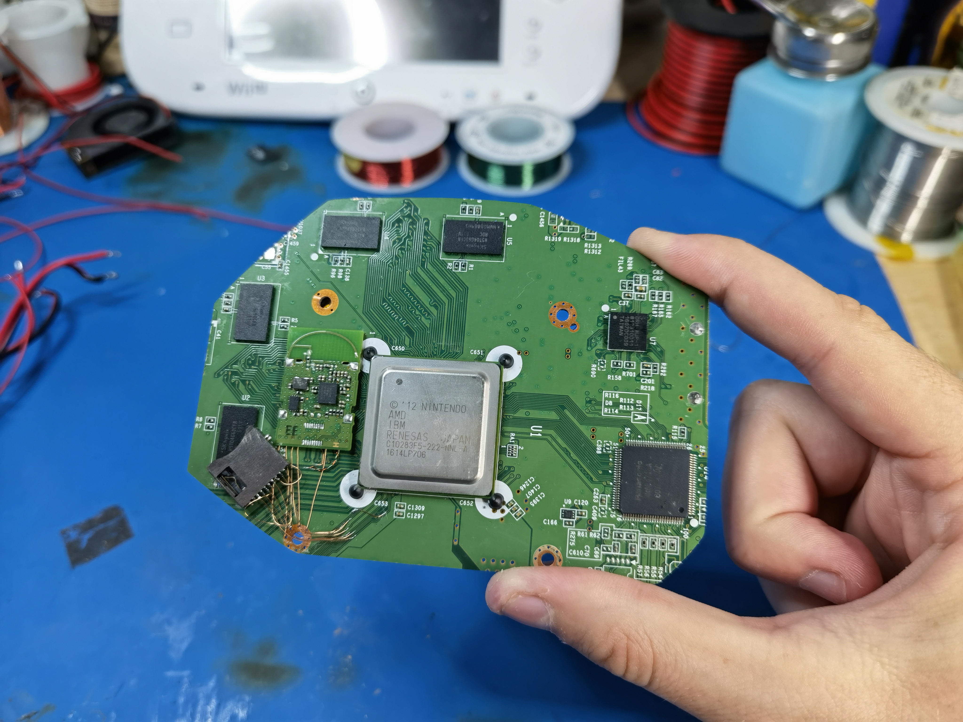
The NAND wiring was tricky. The NAND, eMMC, WiFi module, and even the debug port for the Pico de_Fuse modchip all connect to the same 0.8mm pitch grid of vias under the SOC! I also had to remove the Wifi module and move it to make room for the NAND daughterboard as mentioned previously.

After reconnecting Wifi and 3.3V/GND:
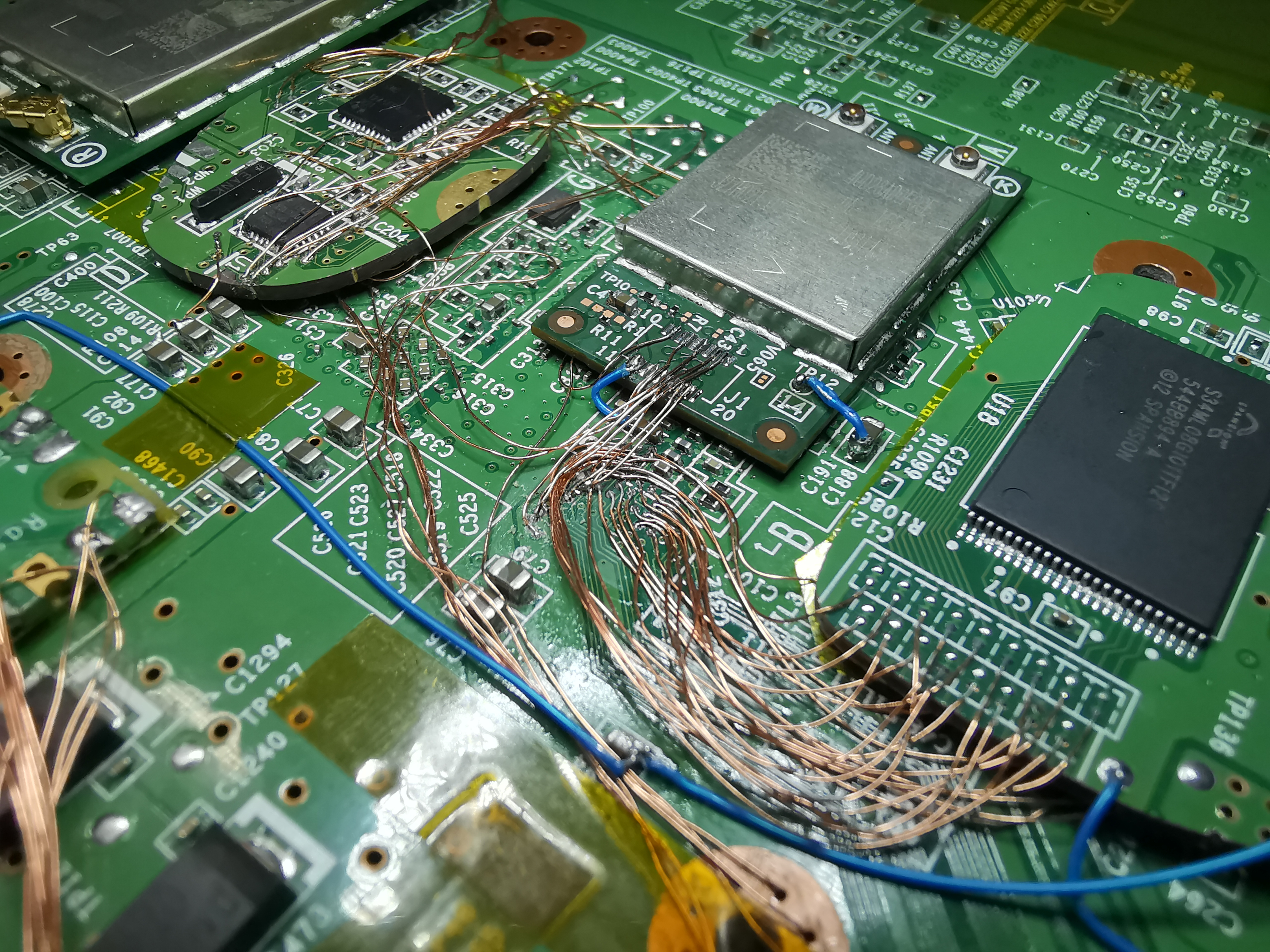
The fact that the components are so spread out has actually been a blessing in disguise. It means we can relocate everything with daughterboards instead of expensive custom PCBs. But a FPC for the NANDs, Wifi, and Pico wouldn't be a bad idea.
It boots! First ever trimmed Wii U! I played some BotW and WWHD, and it's totally stable.
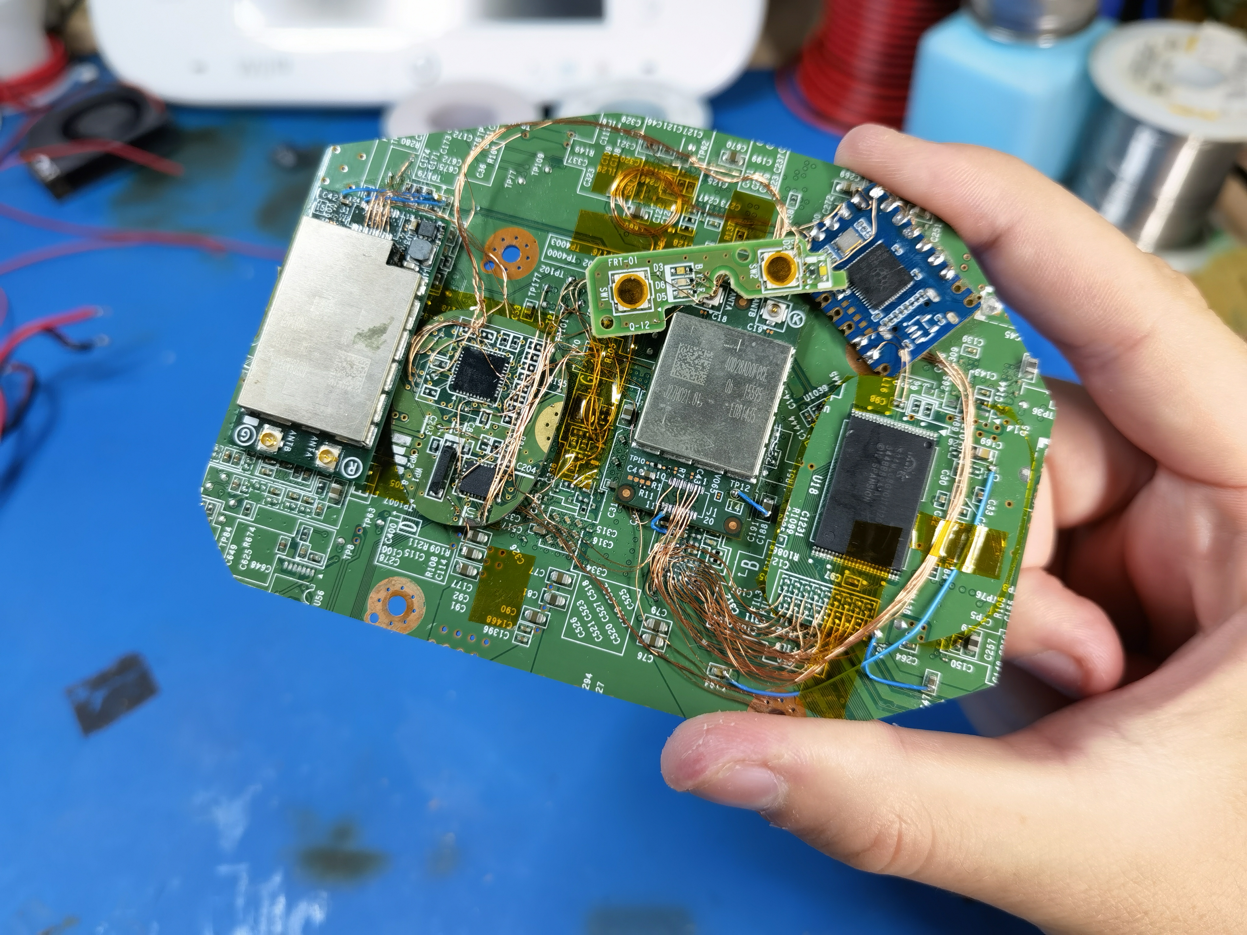
And finally, a size comparison with a stock mobo. Again, this is just a preliminary trim. Final trim coming soon!
I cut out the SMC and RTC from a WUP-01 motherboard. I was so excited, I forgot to take microscope photos of the bare daughterboard! But here are some pics of the relocation.
Because I didn't rewire the SMC pins that normally enable the rear USB port protectors, I had to remove them and jumper 5V across the pads.
Despite taking shortcuts like this, the SMC and RTC still required an annoying amount of wiring. I2C for the SMC, EXI for the RTC, power button, R/B/Y LEDs, and all the GPIOs for the wireless modules. But the relocation worked!
After this, I spent some time cleaning up and consolidating the wiring and regs in preparation for a preliminary trim.
I was able to run the 3.3V line from the Pico's onboard regulator, which was convenient. I also moved the Pico to beneath the SOC (not shown).
Next up was the flash memory. Since the eMMC and NAND are tied to the console, you can't use ones from a different motherboard without some dumping/reflashing shenanigans. In other words, the NAND daughterboard must be cut from the same motherboard. This is an irreversible step and must be done at the same time as a mobo trim, which is why I saved this relocation for last.
NAND/eMMC daughterboard...
...and with wires attached. The eMMC uses 4-bit SDIO (6 wires) and the TSOP NAND uses the same ONFI type interface as the Wii NAND (17 wires).
Here's the trimmed Wii U motherboard after sanding. Keep in mind this is just a preliminary trim for testing purposes.
The NAND wiring was tricky. The NAND, eMMC, WiFi module, and even the debug port for the Pico de_Fuse modchip all connect to the same 0.8mm pitch grid of vias under the SOC! I also had to remove the Wifi module and move it to make room for the NAND daughterboard as mentioned previously.
After reconnecting Wifi and 3.3V/GND:
The fact that the components are so spread out has actually been a blessing in disguise. It means we can relocate everything with daughterboards instead of expensive custom PCBs. But a FPC for the NANDs, Wifi, and Pico wouldn't be a bad idea.
It boots! First ever trimmed Wii U! I played some BotW and WWHD, and it's totally stable.
And finally, a size comparison with a stock mobo. Again, this is just a preliminary trim. Final trim coming soon!
Attachments
-
 4.2 MB Views: 77
 -
 10.4 MB Views: 78
- Joined
- Apr 29, 2020
- Messages
- 92
- Likes
- 114
Wow that last pic really shows tremendous progress, thanks to your work we’re entering a new dimension! Looking forward to future updates! (And I totally root for FPCs)
I thought the exact same thing. They're eerily similar!Dang, you've been busy! Awesome update. Now the trimmed board is about the size of a wii mini stock board!

A "Wii U Mini" using a modest trim like this would be pretty cool. You could keep the original 1v/1.15v regs and front panel, and just shorten the main part of the case. A ton of work for something that's not functionally any different from a stock console, though...
Last edited:
- Joined
- May 11, 2021
- Messages
- 24
- Likes
- 13
- Location
- Somewhere on this Earth...
- Portables
- e^(i x π) + 0!
If you use a USB drive/SD card, you can homebrew the vWii, making it so you can run both games and channels. Check wiiu.hacks.guide
Also, you are AMAZING Yveltal! We might be getting a Wii U Portable sooner than we think...
Also, you are AMAZING Yveltal! We might be getting a Wii U Portable sooner than we think...
Ysecond
.
- Joined
- Aug 30, 2023
- Messages
- 5
- Likes
- 0
For now,without disc drive,can't even launch homebrew,wiivc is the only way. I'm not sure if Priiloader can solve this problem.If you use a USB drive/SD card, you can homebrew the vWii, making it so you can run both games and channels. Check wiiu.hacks.guide
I got burned out and took a month off Wii U stuff. But I'm back with big news!
Presenting... the LOLWUT trim!
WUT stands for Wii U Trim. And it's also only one letter off from "WUP" which is Nintendo's designator for Wii U motherboards.
Here it is compared to a stock WUP-50. The board area has been reduced by more than 70%.
the LOLWUT trim's dimensions are 81 x 111mm-- only slightly larger than the venerable OMGWTF!
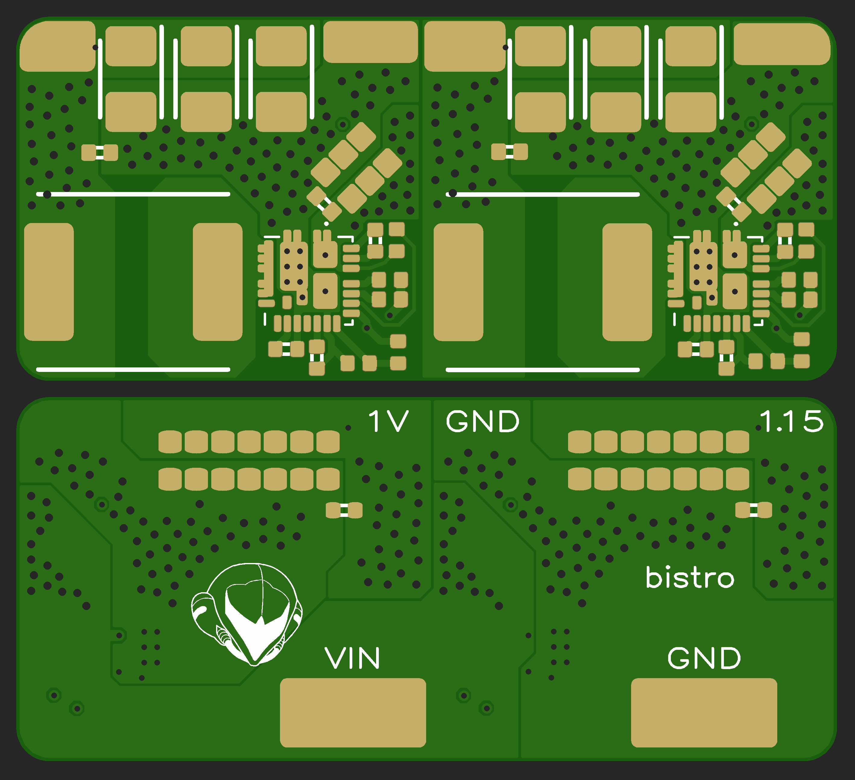
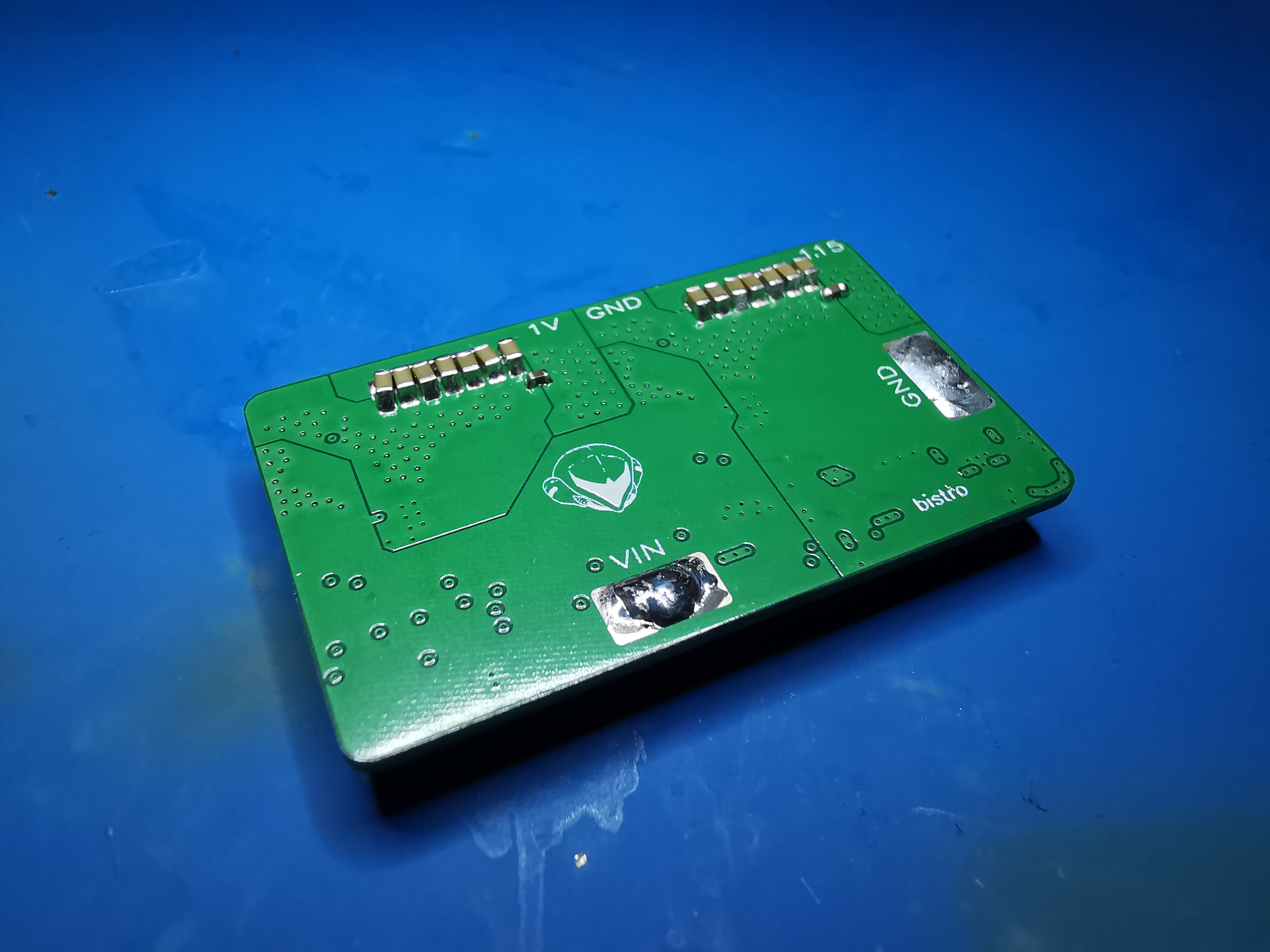
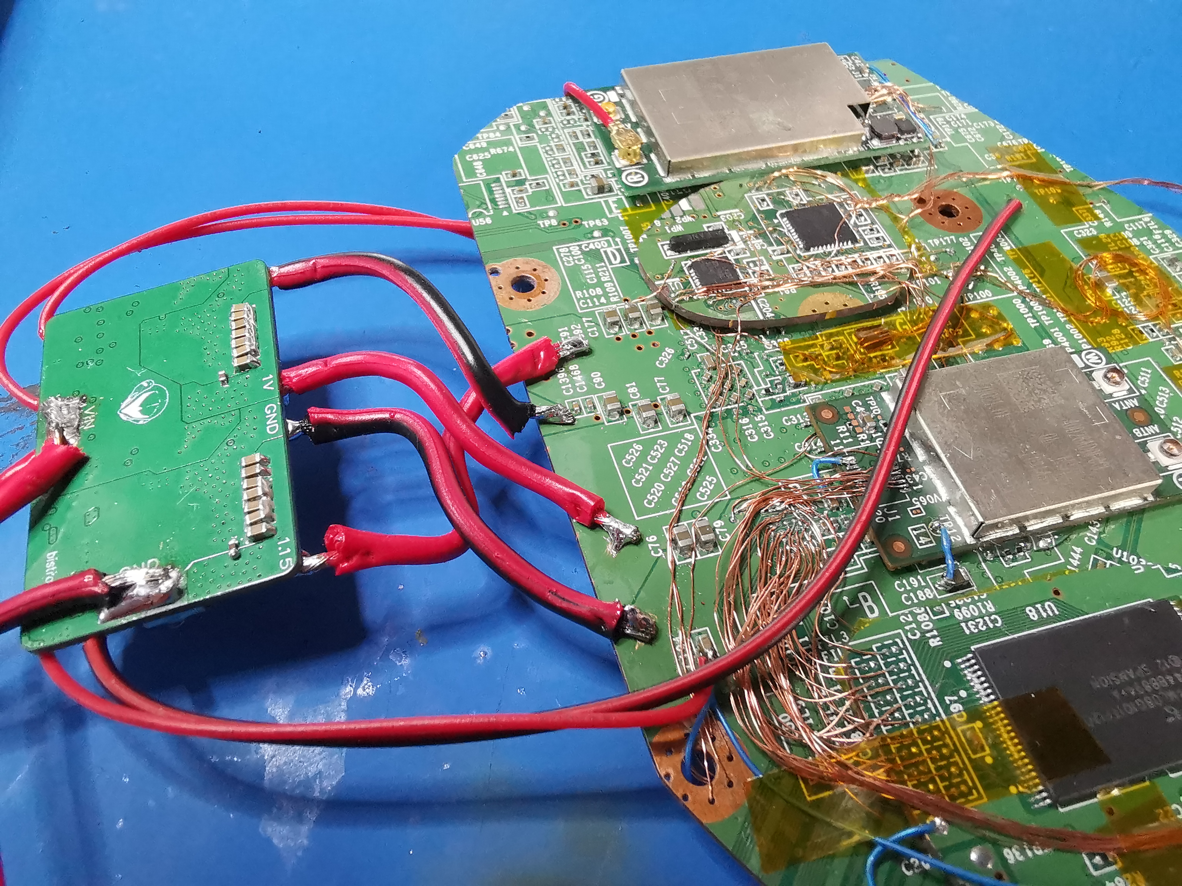
Ok, let me back up a bit to document the stuff that led up to the final trim. In late August I decided to integrate the other voltage regulators the Wii U needs onto my SiC43X regulator board. Came out to 37x23mm in the end. I wanted 2oz/in² copper, but forgot that the trace/space specs are looser with heavier copper, so I had to get 1oz.
I assembled the Bistro reg board with my new Pixel Pump from Robins Tools! Highly recommend it, it's a fun little tool and way better than tweezers for chipscale parts.
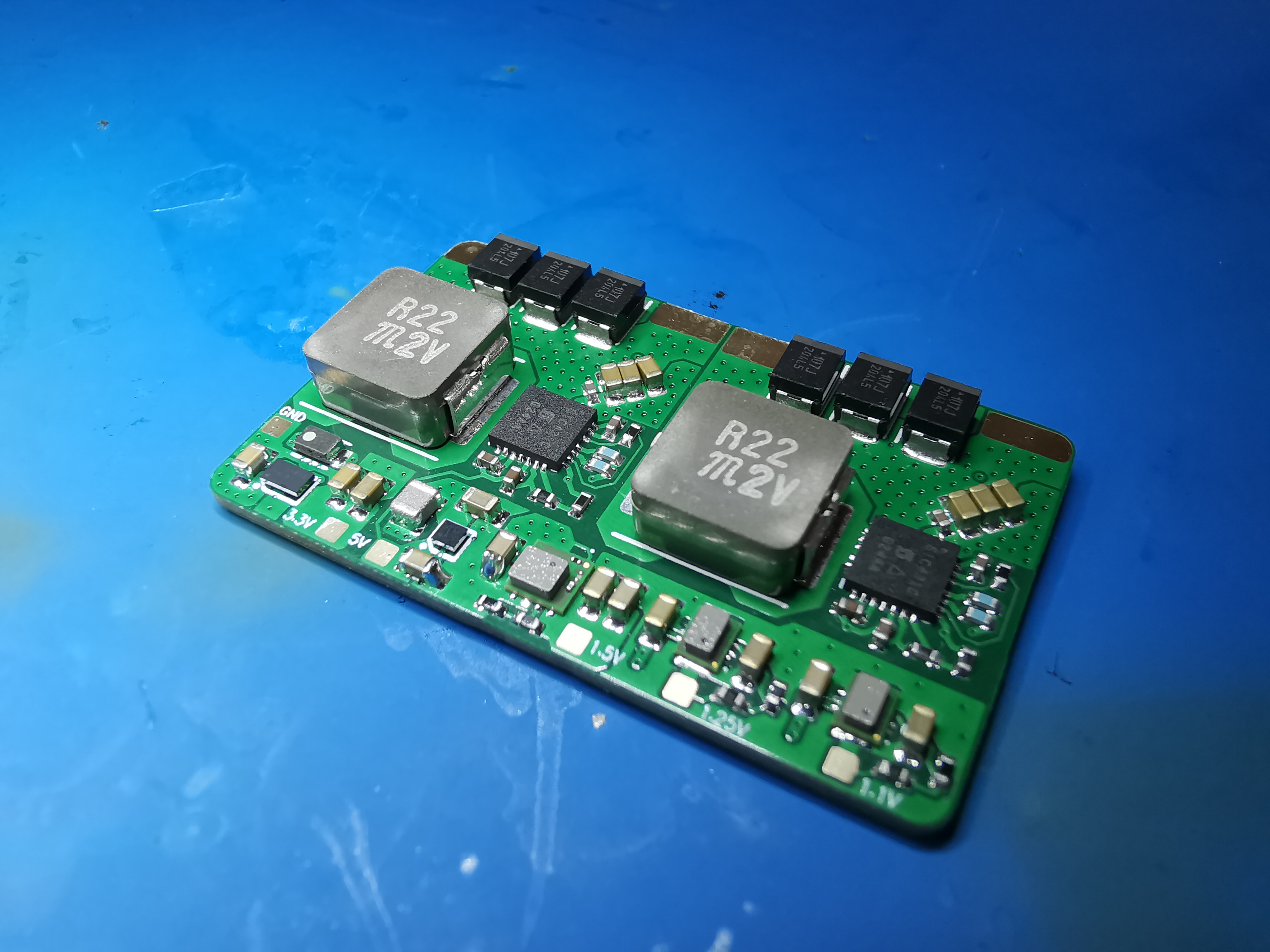
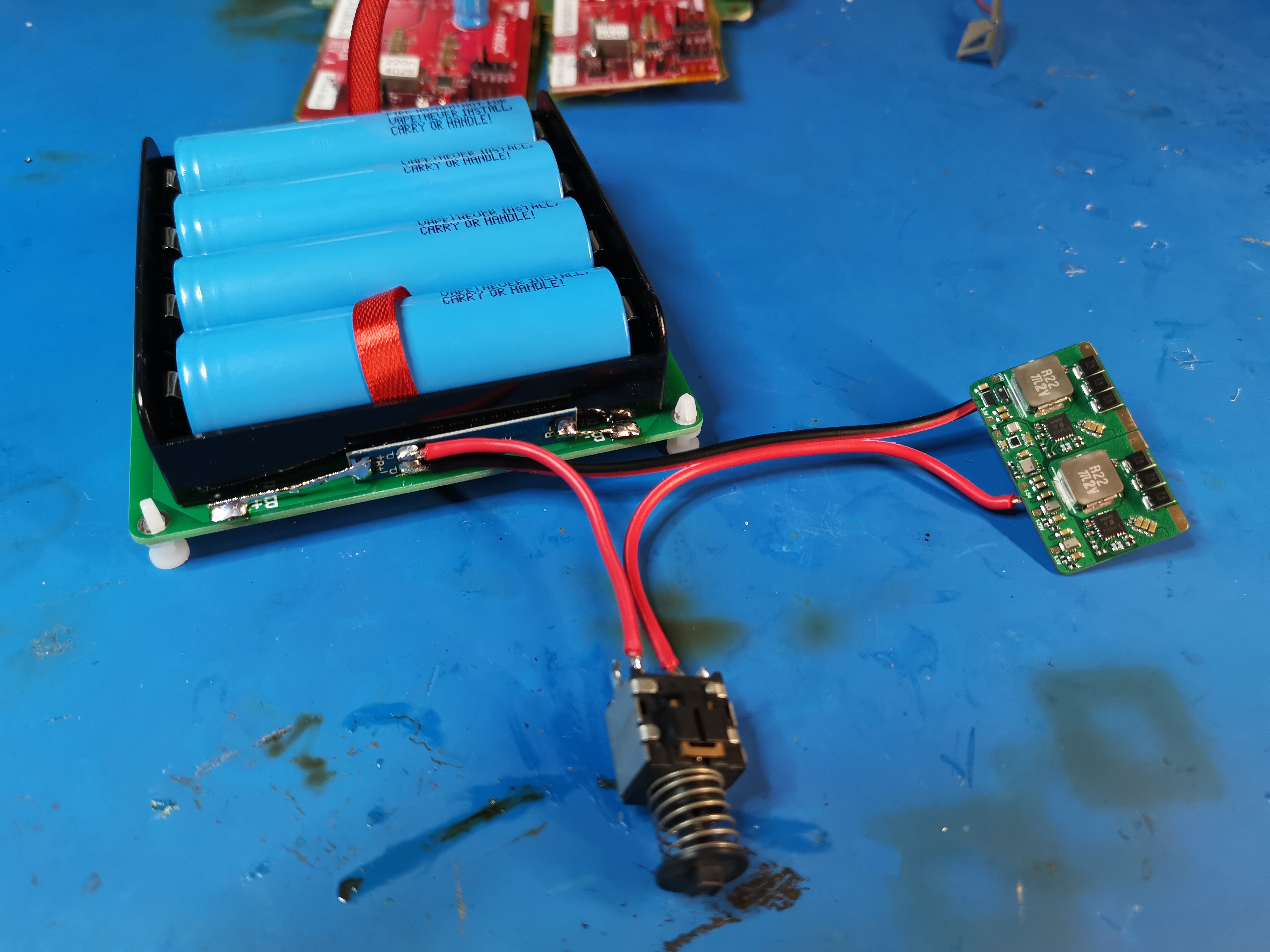
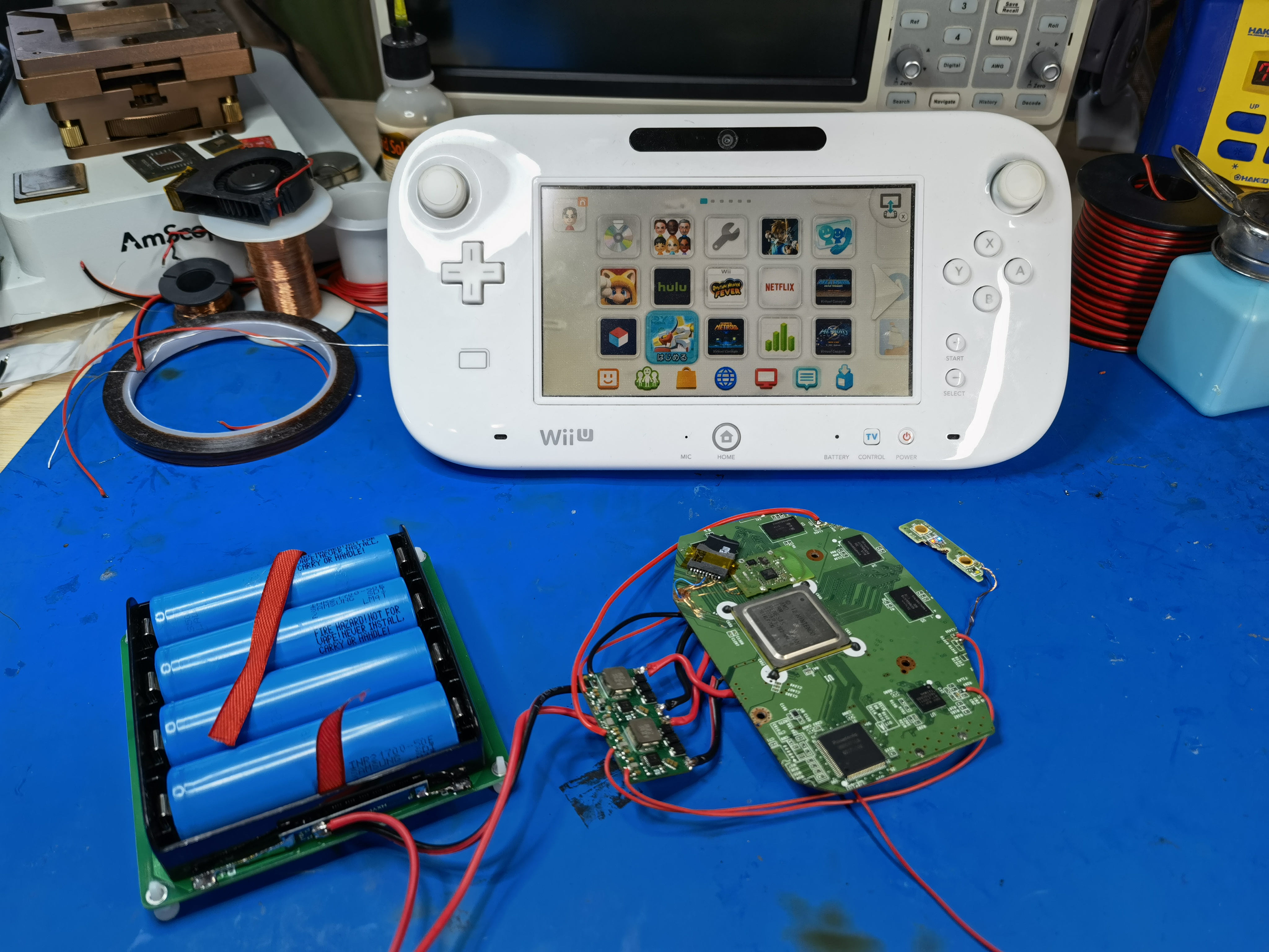
I put together a 1S4P 21700 setup to power everything. The mobo fired right up with the custom reg board! I did have to increase the 1.1V reg voltage to 1.15V to get the DRH IC stable so the Gamepad wouldn't disconnect sporadically.
Next up was relocating the Pico de_Fuse modchip. The testpads it was connected to originally were going to be trimmed off, so I had to rewire the debug port pins (8 wires) to the same patch of vias as the eMMC, NAND, and WiFi. Virtually all of the vias in this area get used. Nice of Nintendo to consolidate all the IO interfaces, but a flex would really help here.
I swapped the fullsize Pico out for a slimmed-down RP2040 Zero while I was doing this.
Last thing I did was tweak some of the SD card wiring (shorting WP and CD to GND closer to the SOC). At this point everything had been relocated within the trim boundaries I had originally envisioned.
I've been theorycrafting the LOLWUT trim for a while. Here's an early mockup from my WUP-01 compendium. By relocating the wireless modules, SMC/RTC and NANDs, the mobo can be cut down to the SOC, RAM, video encoder, and DRH IC. Theoretically you could cut off the video encoder and DRH and relocate them with trace scratching, but I'm not gonna go that far.
As you've all seen already, the WUP-50 equivalent is even more compact, thanks to the RAM being moved inward, along with the smaller SOC.
Pre-trim pic. Man, this post is kinda backwards, huh?
I trimmed, sanded, checked resistances, removed an MLCC I nicked, wired up the bistro reg board...
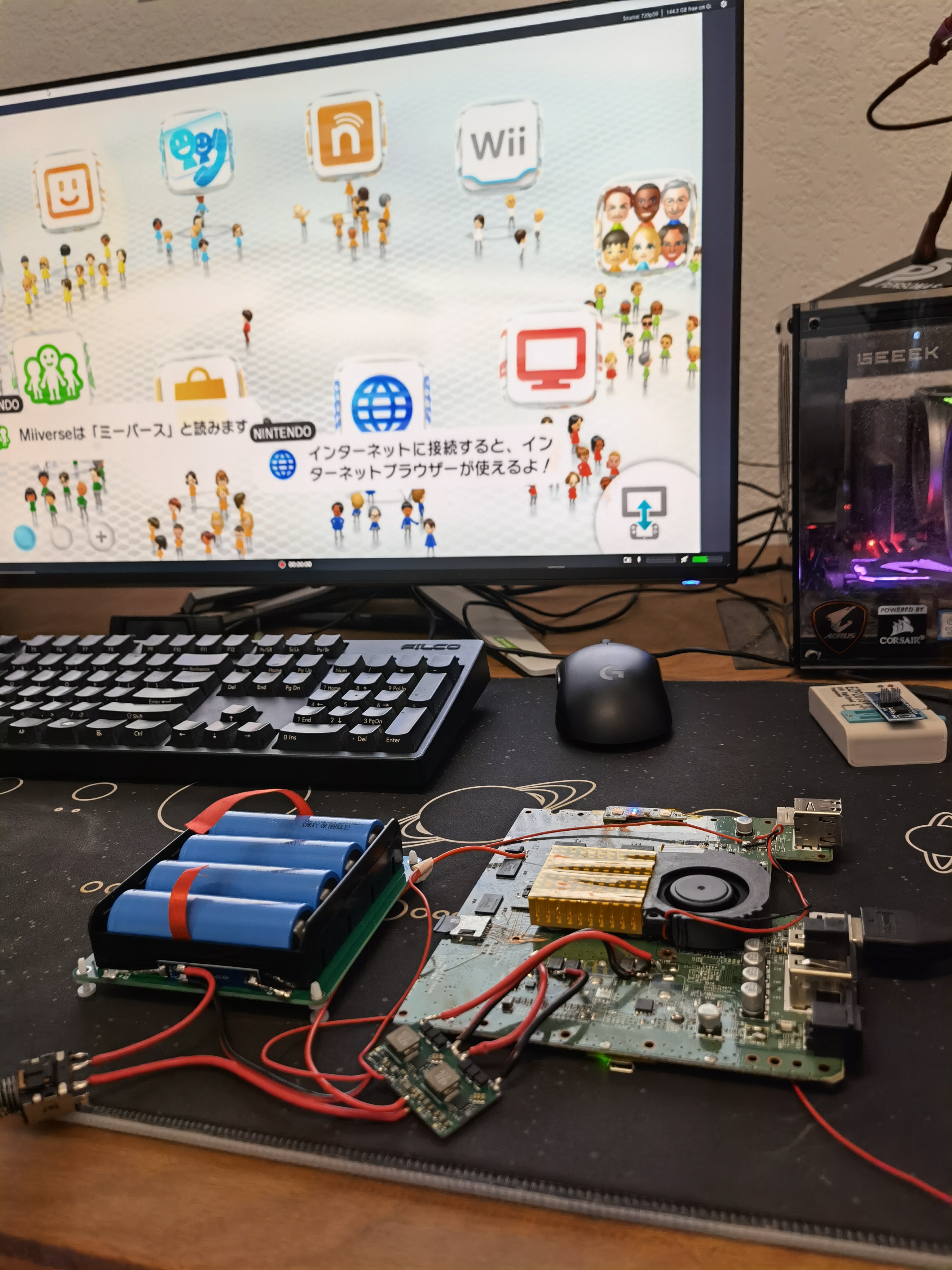
It boots! While I haven't wired up HDMI or composite, the trimmed mobo of course still displays on the paired Gamepad.
Video of trim booting:
Video of trim playing Breath of the Wild, feat. jet engine 5V fan and World's Worst Loading Times:
And some final close-up glamour shots:
Regarding the trim guide, it's still a ways off. I need to scan a WUP-50 to make the diagrams for the guide-- all my trim development has been done with the WUP-01 compendium and pencil+paper. Regardless, my goal is to release The Definitive Wii U Trimming Guide before the end of the year!
Presenting... the LOLWUT trim!
WUT stands for Wii U Trim. And it's also only one letter off from "WUP" which is Nintendo's designator for Wii U motherboards.
Here it is compared to a stock WUP-50. The board area has been reduced by more than 70%.
the LOLWUT trim's dimensions are 81 x 111mm-- only slightly larger than the venerable OMGWTF!
Ok, let me back up a bit to document the stuff that led up to the final trim. In late August I decided to integrate the other voltage regulators the Wii U needs onto my SiC43X regulator board. Came out to 37x23mm in the end. I wanted 2oz/in² copper, but forgot that the trace/space specs are looser with heavier copper, so I had to get 1oz.
- x2 SiC431C 24A buck regulators for 1v and 1.15v (CPU + GPU)
- x2 MUN3CAD01-SB 1A bucks for 1.1V and 1.25V (for DRH IC)
- x1 MUN3CAD03-SE 3A buck for 1.5V (RAM)
- x1 TPS63810YFFR 2.5A buck-boost for 3.3V
- x1 FAN48610BUC50X 5V 1A boost (USB)
I assembled the Bistro reg board with my new Pixel Pump from Robins Tools! Highly recommend it, it's a fun little tool and way better than tweezers for chipscale parts.
I put together a 1S4P 21700 setup to power everything. The mobo fired right up with the custom reg board! I did have to increase the 1.1V reg voltage to 1.15V to get the DRH IC stable so the Gamepad wouldn't disconnect sporadically.
Next up was relocating the Pico de_Fuse modchip. The testpads it was connected to originally were going to be trimmed off, so I had to rewire the debug port pins (8 wires) to the same patch of vias as the eMMC, NAND, and WiFi. Virtually all of the vias in this area get used. Nice of Nintendo to consolidate all the IO interfaces, but a flex would really help here.
I swapped the fullsize Pico out for a slimmed-down RP2040 Zero while I was doing this.
Last thing I did was tweak some of the SD card wiring (shorting WP and CD to GND closer to the SOC). At this point everything had been relocated within the trim boundaries I had originally envisioned.
I've been theorycrafting the LOLWUT trim for a while. Here's an early mockup from my WUP-01 compendium. By relocating the wireless modules, SMC/RTC and NANDs, the mobo can be cut down to the SOC, RAM, video encoder, and DRH IC. Theoretically you could cut off the video encoder and DRH and relocate them with trace scratching, but I'm not gonna go that far.
As you've all seen already, the WUP-50 equivalent is even more compact, thanks to the RAM being moved inward, along with the smaller SOC.
Pre-trim pic. Man, this post is kinda backwards, huh?
I trimmed, sanded, checked resistances, removed an MLCC I nicked, wired up the bistro reg board...
It boots! While I haven't wired up HDMI or composite, the trimmed mobo of course still displays on the paired Gamepad.
Video of trim booting:
Video of trim playing Breath of the Wild, feat. jet engine 5V fan and World's Worst Loading Times:
And some final close-up glamour shots:
Regarding the trim guide, it's still a ways off. I need to scan a WUP-50 to make the diagrams for the guide-- all my trim development has been done with the WUP-01 compendium and pencil+paper. Regardless, my goal is to release The Definitive Wii U Trimming Guide before the end of the year!
Last edited: