What's new

PS2 Ultra Slim

Stitches

2 and a Half Dollarydoos
Staff member
.
.
Joined
Feb 5, 2017
Messages
4,215
Likes
3,303
Location
Banana Bender Land, Australia
Portables
6
This is how it looks printed in black resin, from PCBWay. Not bad, the only problem is it feels fragile, like it can break if falls. The original PS2 was silver satin, so that's why the color of the controller ports.
Yeah resin is a bit fragile, no way around that sadly. I like the two tone appearance that the pale ports provide. Very nice build!
 

DoeKe

.
Joined
Oct 26, 2024
Messages
28
Likes
17
I got tired of the stock squishy disc tray switch. I absolutely couldn't stand how that felt when turning the PS2 on. So I decided to use some clicky buttons I had ordered previously for the power button. They were slightly too big, but I got it working! Had to shave down the plastic power button a little bit, but now it fits great. No more accidentally turning on the PS2 with a slight touch. And it gives a nice firm click when pressing the power button.

I kinda also want to make a better power solution instead of just using a wire from the board to the USB-C port. Something like a port or plug that I can just solder onto the board and have the other plug on the cable, easy to detach without soldering.

And I also still want to figure out how to add a power LED, so I'll need to do more research on that as well.
 

DoeKe

.
Joined
Oct 26, 2024
Messages
28
Likes
17
Hi!

All my PS2s are also chipped.

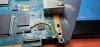
This one is using Modbo 5.0 (but same issue using FMCB)

OPL 1.2 for MX4IO support

Ack and Ground is bridged.

The issue may be that I didn't use the resistance?

I read all sorts of conflicting guides saying that it is not necessary, but then why include it in the first place?

I think I initially followed Macho Nacho's video, but then I noticed that when he installed the ElectronAnalog HDMI mod, he didn't shield the component wires to ground which IMO isn't great advice as that will introduce interference (I tried without shielding and it was night and day).

So I am wondering if his advice to skip the resistance is also as misguided? In reality, what is the purpose of that resistance?

Q


It depends what look you are after, and how much money you have, if you care to elaborate on those points a little bit?

As for the files to print, I agree the initial post is a little bit confusing as it links to an updated version that does not include the additional button and SD card bracket. I myself have got caught out as well and placed an initial order that had to be replaced as I realised the additional parts to be printed are in the actual original download.

Q


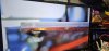
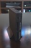
I've attached pictures of my latest build to give you an idea.

The material is is:

HP MJF Nylon PA12

The color is:
Dyed black

The texture and finish is:
Shot peened


I used a website called CraftCloud that guides you through the whole process and makes it easy for you, then gives you a selection of 3D printer vendors to chose from depending of what you selected, your location etc etc, give it a try and it will show you what the finishes and materials look like.

If you want transparent, the PCBway transparent resin is the answer, but be prepared to pay extra.

Q


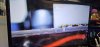
I also had noise AnalogElectron.

I fixed it in 2 steps.

Step one, shield the cables, AnalogElectron even has the ground via holes for this.

Step two, routing was really important for me.

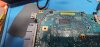
I isolated main ground and 5 volt (or is it 3.3) and ran them down under the motherboard to come out the other side.

The shielded video wires run on the top side of the motherboard right above the main shield plate, this way I avoid interference with 5 volt and all the other components from the motherboard

Same for audio wire, except I ran them a bit further down.

The video, audio, and power wires never intersect.

This has reduced the noise to very closely match my other PS2 that uses component+RetroTink 4K, where before it uses to be very noticeable and distracting.

Hope this helps.

Q


Just a note, maybe this was trimmed after the fact so ignore me if so, but you dont need to hookup the whole right row of that modbo except CX. SX is for PS1 and Y to A is for DVD, which obviously, we don't need anymore. This will save you lots of time on your next build as those B/G/H/I on this model aren't exactly fun soldering jobs
--

So... update on my own build..

So yes, resin is very VERY fragile, and I found that out the hard way when trying to put heat inserts into the shell.
Thing just literally crumbled apart under the heat like a saltine cracker, and poof, no more screw holes..

So I'm probably gonna just order a new NYLON shell, something very similar to what @PurpleSkyz posted above.
I'm going to add my own touch/custom logos to the 3D model, and have it printed on black nylon to match the other PS2 consoles on my shelf.

Maybe even paint the logo or something on the shell, still working on that.

But yeah, don't try melting resin, bad idea, it won't work. xD
 
Joined
Sep 30, 2024
Messages
39
Likes
35
Location
Laurium, MI
Portables
2
@DoeKe Thank you for that information!

I have been wanting to add threaded inserts to my resin shells but was hesitant to do so.

Another thing I about the resin shells is that they are easily dissolved by IPA. I was working on the board and spilled some IPA on my work mat, and the shell dissolved where it was touching the IPA. It was so frustrating to spend/wait that much and have it destroyed so quickly. I now paint them right away to help protect the shell. But lesson learned.

I get the shells printed at PCBWay, 3–4 at a time, so it works out to about $43 per shell. Not a huge loss cash wise butstill having to wait weeks to get another.
 

DoeKe

.
Joined
Oct 26, 2024
Messages
28
Likes
17
No worries, one of us has to learn so that others know what not to do in the future!

I'm also trying to teach myself how to use blender so that I can do the model editing myself to add my logos to it for when I order the new shell.

Definitely a bit of a learning experience, and a lot to figure out. I would LIKE to get the logos into the shell like how the Sony logo is and how the shapes are, and not embossed, but I've only been able to figure out embossing thus far. Embossing doesn't look bad in the slightest, but I would much rather everything look uniform.

I'm stupidly picky about aesthetics.
 
Joined
Nov 29, 2024
Messages
13
Likes
5
Location
London
@DoeKe

Now it's making sense as to what was going on. Ha! I think you've got it now. Another thing to note is that the MX4SIO doesn't always show up right away on that version of OPL because the default is USB. You have to use the D-pad to select the next location.

Format your microSD card as exFAT and put your games in a folder named "DVD" in the root directory. Also, a handy tool is "OPL Manager" to get all the artwork, saves, cheats, etc., set up. You probably already know this.

@PurpleSkyz

Just something else to consider if the microSD card isn't showing up without taking it out and putting it back in: it could be due to using that version of OPL. It typically defaults to USB, and you have to press right or left on the D-pad to select the MX4SIO. I know that in launchELF, you have to select "mass0" to open that file location, and then when you back out, "MX4SIO" shows up in the file tree. Maybe you already know this, but I'm just throwing out ideas to help.
Sorry for my late reply!

I tried yet another SD card and this one worked fine, so it turned out it is very particular about which SD card to use

Q.
 
Joined
Sep 30, 2024
Messages
39
Likes
35
Location
Laurium, MI
Portables
2
What cards did you try, which failed. I have only been using the Samsung cards that Tito recomends.

Thanks for your help!
 
Joined
Oct 29, 2024
Messages
7
Likes
2
Small update. I got another ps2 for cheap in town so now I'm doing one from a silver ps2 79k and one from a Black ps2. Parts needed came in on the 24th so will hopefully be showing off 2 designs soon! The 2nd one is bought had bugs in it though so I had to do a lot of cleaning.
 

DoeKe

.
Joined
Oct 26, 2024
Messages
28
Likes
17
What cards did you try, which failed. I have only been using the Samsung cards that Tito recomends.

Thanks for your help!
I would also say to try using Rufus to format the SD cards, cause I've not had luck with formatting some cards and getting them to show up on the PS2 until I used Rufus to format them. I was able to get a Lexar 1TB, Samsung 512TB, and a SanDisk 32GB MicroSD card to work using this method.
 

mc94

.
Joined
Aug 14, 2024
Messages
4
Likes
0
I modified a v1.2 case to accomodate a PD trigger board to use instead of a regular DC jack. @Wesk might want to add this somewere in one of his posts
This is for a HW-398 trigger board.
View attachment 33851

Make sure your trigger/decoy board is set to 9V
There are no guarantees that powering your console this way will not fry it. PS2 79XXX is rated for 8.5V input so do this at your own risk.


The print for me was a snug fit and I think you can just push the board in without a retainer but you risk displacing it. You need to push the buisiness end into the hole first and then push the rest of the board flat onto the platform.
You will need to use 2 M3x6 screws to mount a retainer. The screw holes are small enough for the screws to self tap. Make sure to not overtighten them else the standoffs will break off.

I am including a test part so you do not need to print the whole half to test fit your board.

CAD files are included so you can modify the design if necessary. The TestPart.step is also included and can be used to modify the other variations of the top shell.
Hi! I've got question regarding the usage of HW-398 trigger board - does it support modern PPS standard chargers which provide 3.7-11v at 5Ampers? Some GaN chargers have support for such standard at theoretically can be use to make 9V/5A output for PS2.
 

DoeKe

.
Joined
Oct 26, 2024
Messages
28
Likes
17
Hi! I've got question regarding the usage of HW-398 trigger board - does it support modern PPS standard chargers which provide 3.7-11v at 5Ampers? Some GaN chargers have support for such standard at theoretically can be use to make 9V/5A output for PS2.
I've found that they do require a specific type of charger. Either a fast charger or super fast charger, as some cheap chargers, or ones that just provide basic charge don't seem to work.

I have these specific chargers, and can confirm that they work very well:
- UGREEN 65W USB C Charger Block, Nexode 4-Port
- SAMSUNG 50W Duo Power Adapter Wall Charger, 2 Ports
- Samsung 25W Wall Charger Power Adapter

I would assume any GaN charger, Fast, or Super Fast Charger for phones would work just as well.
I just tend to buy multi-port ones to use on multiple consoles at once.

However, something like this should work, too:
UGREEN 30W USB C Charger, Nexode Foldable GaN PPS Compact Fast Wall Charger Block
 

mc94

.
Joined
Aug 14, 2024
Messages
4
Likes
0
I've found that they do require a specific type of charger. Either a fast charger or super fast charger, as some cheap chargers, or ones that just provide basic charge don't seem to work.

I have these specific chargers, and can confirm that they work very well:
- UGREEN 65W USB C Charger Block, Nexode 4-Port
- SAMSUNG 50W Duo Power Adapter Wall Charger, 2 Ports
- Samsung 25W Wall Charger Power Adapter

I would assume any GaN charger, Fast, or Super Fast Charger for phones would work just as well.
I just tend to buy multi-port ones to use on multiple consoles at once.

However, something like this should work, too:
UGREEN 30W USB C Charger, Nexode Foldable GaN PPS Compact Fast Wall Charger Block
You missed the point of my question. These specific chargers that you sent work, sure but they can't provide 5A at 9V through PPS... Advertisment of HW-398 have usually written that they support PPS handshake and some people have issues with it. PPS is the only way that you can have 5A at 9V. For example this one from Anker have compatibility with PPS and can provide range (PPS): 4.5V-20V, 5A (100W Max). This is really cool but like I said some people say that HW-398 board cant communicate using PPS and just use 9V 3A from PD 3.0...
 
Joined
Jan 14, 2025
Messages
5
Likes
1
hey so i have one of those boards that does not have a power switch ive followed titos build do far but i dont know where to cut the trace and i am also not getting power

hey so i have one of those boards that does not have a power switch ive followed titos build do far but i dont know where to cut the trace and i am also not getting power
i am new nice to meet you all:D
 
Joined
Sep 30, 2024
Messages
39
Likes
35
Location
Laurium, MI
Portables
2
hey so i have one of those boards that does not have a power switch ive followed titos build do far but i dont know where to cut the trace and i am also not getting power
Do you mean the lid switch? When there is no lid switch you can skip that step (cutting the trace).

Can you explain "not getting power" more, please?

If you mean you cannot power it on. You need to ground the reset pad with a pb. Read up on this thread it's covered a few times with some clever solutions.
 
Last edited:
Joined
Jan 14, 2025
Messages
5
Likes
1
Thank you for the reply and I'll take some pictures in the morning but I've installed a pb on it with the reset soldered to one of the pins and ground right on the board does it matter if both legs are soldered to the board? when I plug it in nothing happens no fan spin up which should be happening at the test the board phase of the video I'm wondering if I need to sand the board a little more but I'm starting to sand the voltage regulator
 
Joined
Sep 30, 2024
Messages
39
Likes
35
Location
Laurium, MI
Portables
2
Here's the pictures of my build so far
I see the problem here: you have the reset pad soldered to ground. It should be connected to the N.O. (normally open) contact on your push button. When you press the button, the reset pad should make contact with ground. Additionally, you have both contacts of the push button tied to ground. One side of the push button should go to ground, and the other should go to the reset pad.

Your board sanding looks delicious. Well done!
 
Last edited:
Top