
How on earth did you melt the 1v tantalum capacitor?
Worklog The WiiCube
- Thread starter icy_system
- Start date
- Joined
- Mar 26, 2023
- Messages
- 134
- Likes
- 95
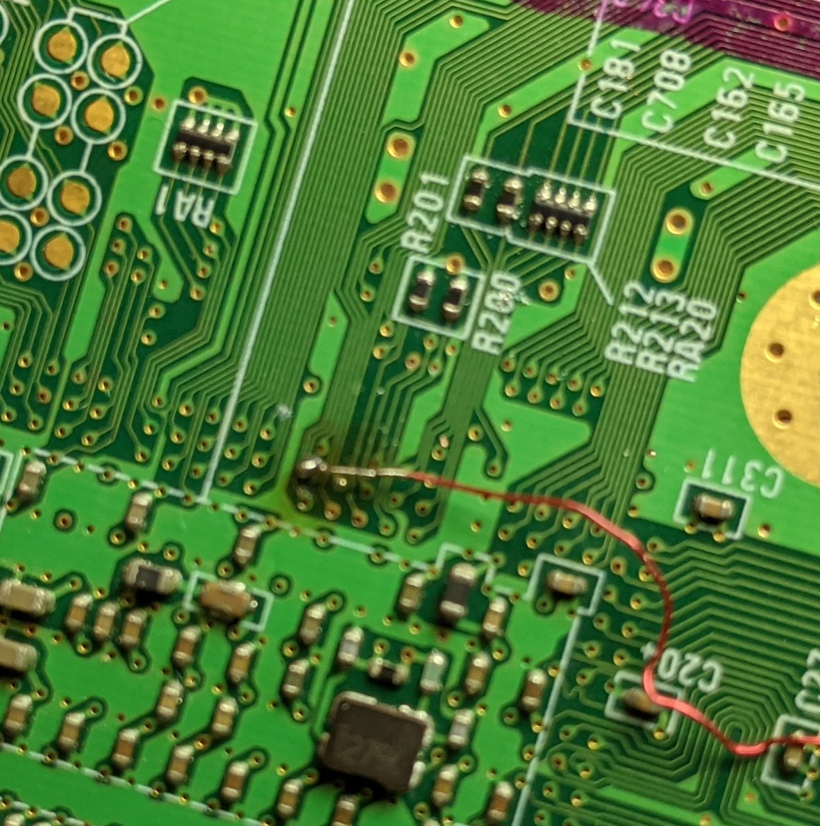
Well, that angle is kind of bad. The part that looked melted really just has some flux or something on it. I probably did melt some if it though.How on earth did you melt the 1v tantalum capacitor?
I must have slipped and held the soldering iron tip to it too long, and now it doesn't work. (Set at ~750)
Is there a way to fix this? I have checked the resistances multiple times.
Last edited:
Just making sure, you aren't trying to measure resistance from both ends of the cap, right? You've got one probe on the 1v side and one probe on a ground location somewhere else?Well, that angle is kind of bad. The part that looked melted really just has some flux or something on it. I probably did melt some if it though.
I must have slipped and held the soldering iron tip to it too long, and now it doesn't work. (Set at ~750)
Is there a way to fix this? I have checked the resistances multiple times.
- Joined
- Mar 26, 2023
- Messages
- 134
- Likes
- 95
Yep, that's what I was doing. Black wire on ground and the red one on any part that says 1v on the Wii trimming guide.Just making sure, you aren't trying to measure resistance from both ends of the cap, right? You've got one probe on the 1v side and one probe on a ground location somewhere else?
Edit: I tried multiple points.
It's possible that the cap is dead then. I'd remove it and check the resistance with it absent
- Joined
- Mar 26, 2023
- Messages
- 134
- Likes
- 95
How exactly do I remove it? Is it soldered on? I desoldered some of the sides, but it still doesn't come off.It's possible that the cap is dead then. I'd remove it and check the resistance with it absent
You'll need a hot air station to remove it the normal way, or if you have two soldering irons you can do a tweezer move to melt the solder on both sides and remove it
- Joined
- Mar 26, 2023
- Messages
- 134
- Likes
- 95
I think it's okay! I found that if I dig a little deeper with the multimeter thing, it shows a reasonable resistance. Why could it be doing that? Was the surface just blocked with flux and solder?You'll need a hot air station to remove it the normal way, or if you have two soldering irons you can do a tweezer move to melt the solder on both sides and remove it
Maybe, yeah. There could also have been a little short under the cap, and the melting cycle you did removed that shortI think it's okay! I found that if I dig a little deeper with the multimeter thing, it shows a reasonable resistance. Why could it be doing that? Was the surface just blocked with flux and solder?
- Joined
- Mar 26, 2023
- Messages
- 134
- Likes
- 95
So does that mean it's safe to use? I'm worried about it getting shorted then.Maybe, yeah. There could also have been a little short under the cap, and the melting cycle you did removed that short
Yeah if the short is gone now, go for it. The worst that'll happen if there is a short or the cap has failed is that it won't boot
- Joined
- Mar 26, 2023
- Messages
- 134
- Likes
- 95
Okay, so I was able to solder wires to all of the voltages, and the resistances match up.
I'll connect this to the PMS to see if it works, but I have one thing that might be an issue. The 1v wire was able to find a spot where the voltage (really resistance) was, but only one spot on the 1v spots works. All the other ones just show 1 in the multimeter when compared to ground. Is this a problem?
I'll connect this to the PMS to see if it works, but I have one thing that might be an issue. The 1v wire was able to find a spot where the voltage (really resistance) was, but only one spot on the 1v spots works. All the other ones just show 1 in the multimeter when compared to ground. Is this a problem?
Last edited:
Unsure, but if I were you I'd redo the 1v and 1.15v wires to be blobbed onto the capacitor contacts. Having the wires blobbed onto the little vias is less than ideal for reliable contact.
Also you need to clean all the flux residue off the board before you run resistance checks. Flux can hold conductive material that causes transient shorts, so clean it up with some 99% isopropyl alcohol first
Also you need to clean all the flux residue off the board before you run resistance checks. Flux can hold conductive material that causes transient shorts, so clean it up with some 99% isopropyl alcohol first
- Joined
- Mar 26, 2023
- Messages
- 134
- Likes
- 95
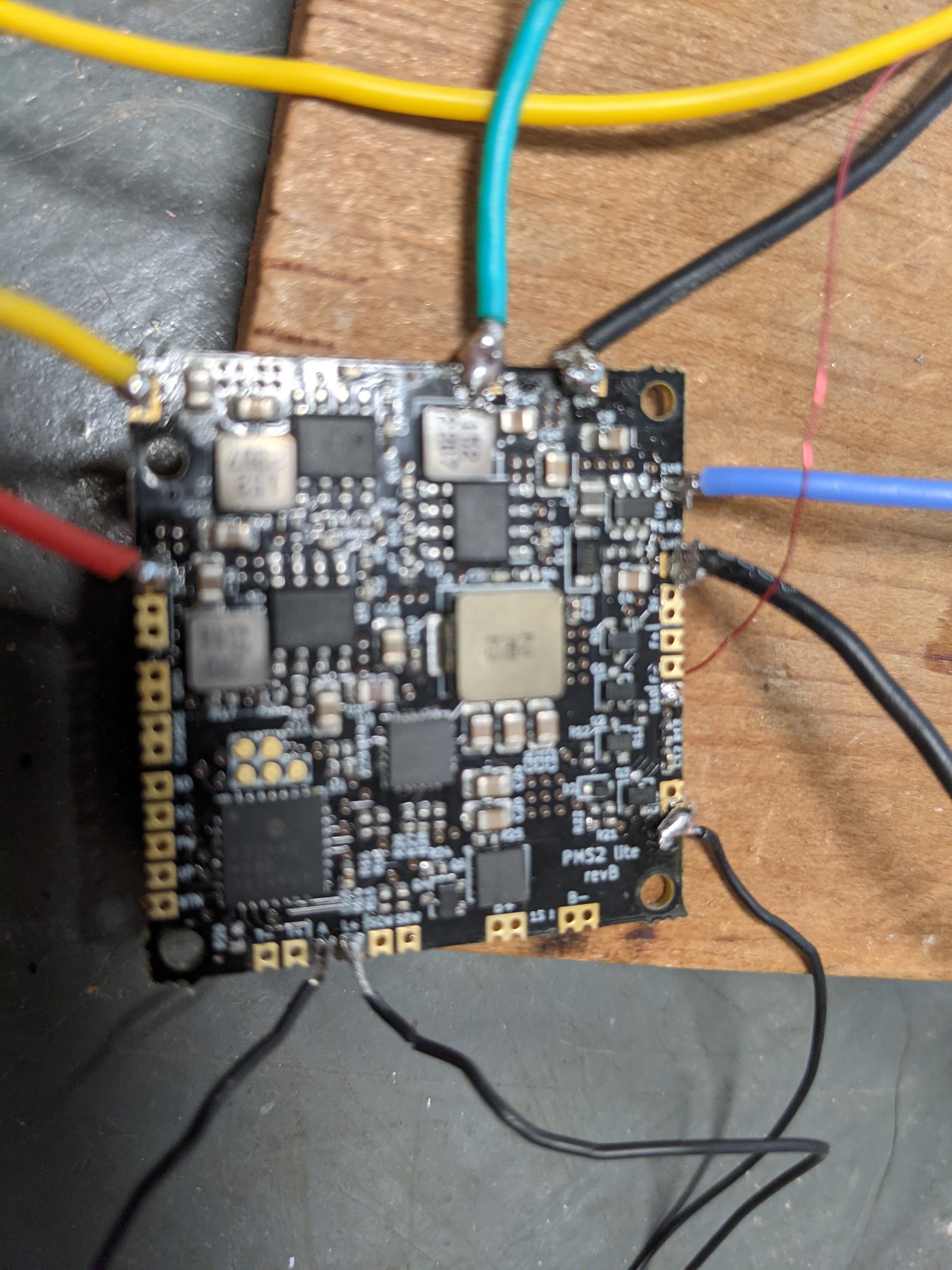
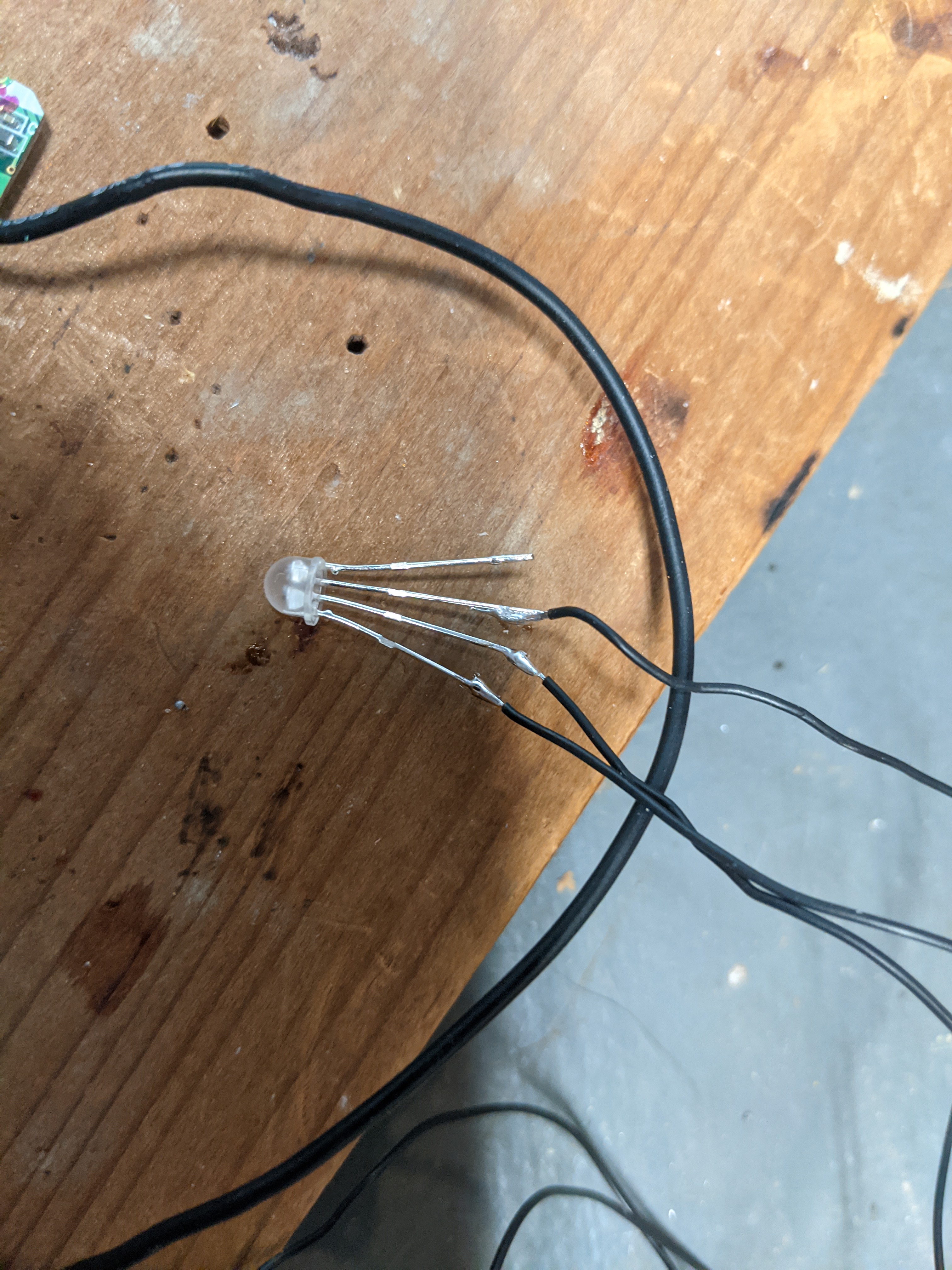
Hey guys! I have made a ton of progress. I soldered all of the voltage lines, U10, and the LED to my PMS Lite.
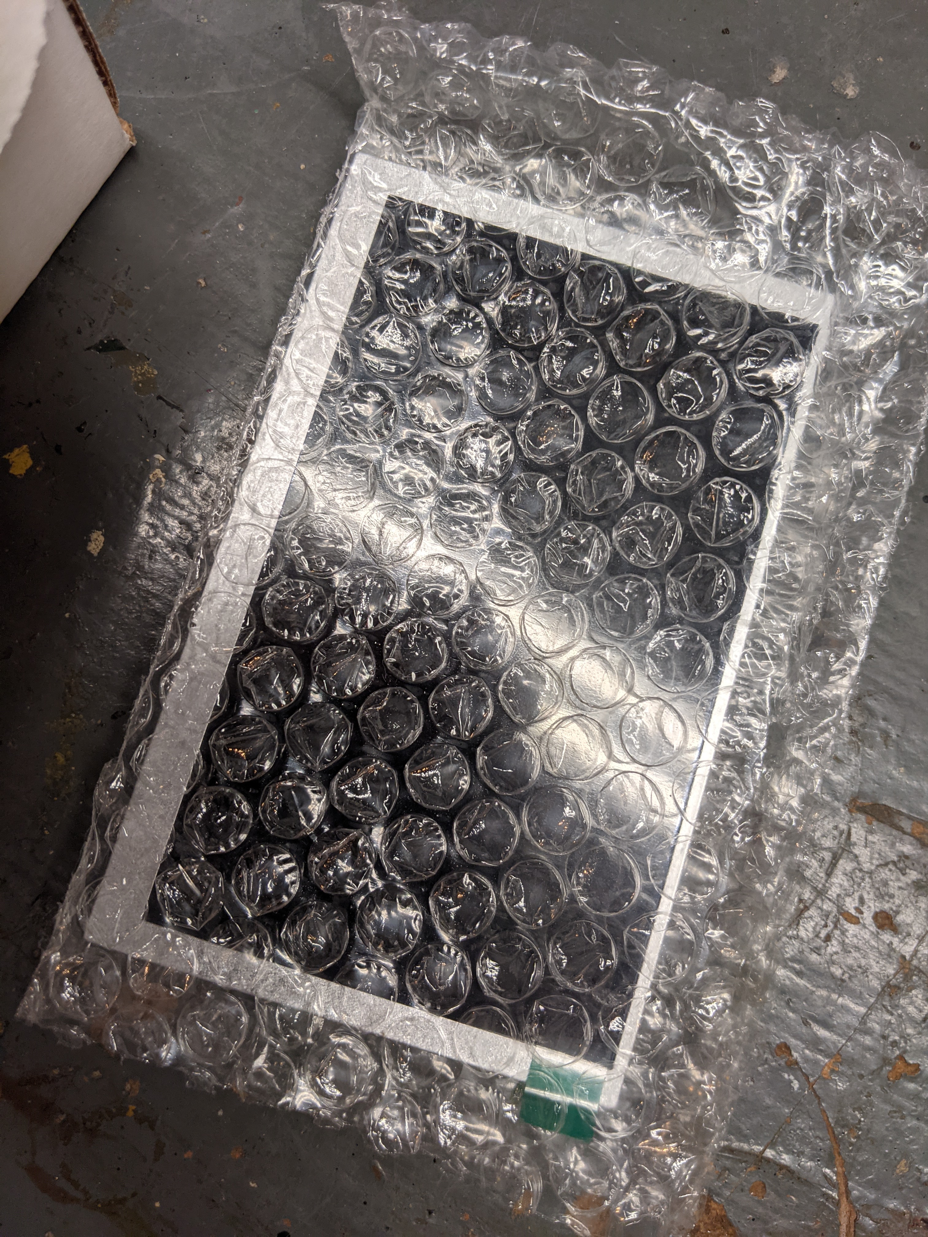
Also some other stuff arrived! I got the batteries, the rvl-amp, the speakers, and the screen.
I also included some more pictures, so you can let me know if anything is wrong.
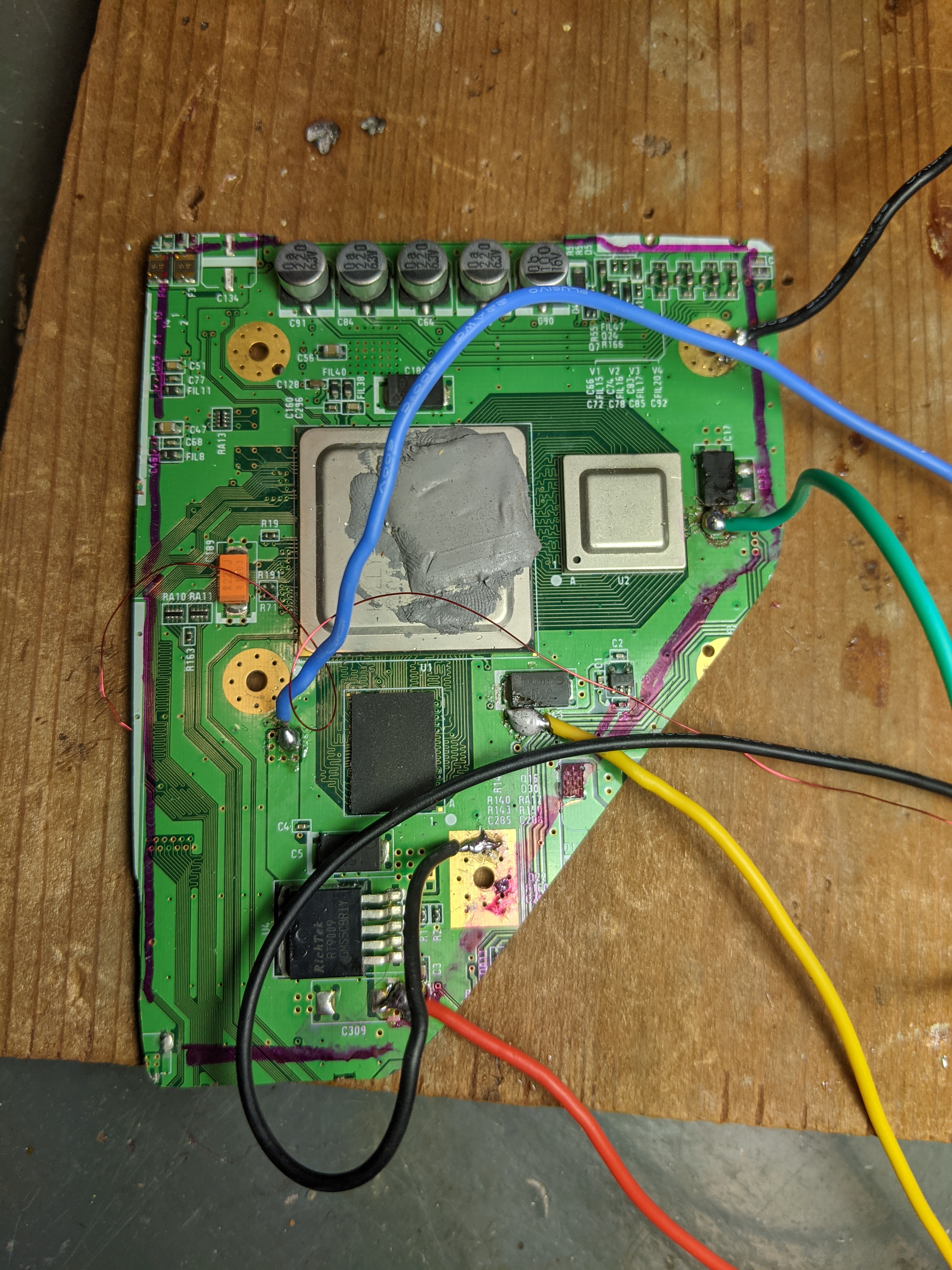
Also, Stitches, I could only solder to the vias for 1v and 1.15v because the other spot you said wouldn't work.
I will test it when I can get the RVL-PD, because that is out of stock rn.
In the meantime, I will have a lot more questions.
Also some other stuff arrived! I got the batteries, the rvl-amp, the speakers, and the screen.
I also included some more pictures, so you can let me know if anything is wrong.
Also, Stitches, I could only solder to the vias for 1v and 1.15v because the other spot you said wouldn't work.
I will test it when I can get the RVL-PD, because that is out of stock rn.
In the meantime, I will have a lot more questions.
- Joined
- Mar 26, 2023
- Messages
- 134
- Likes
- 95
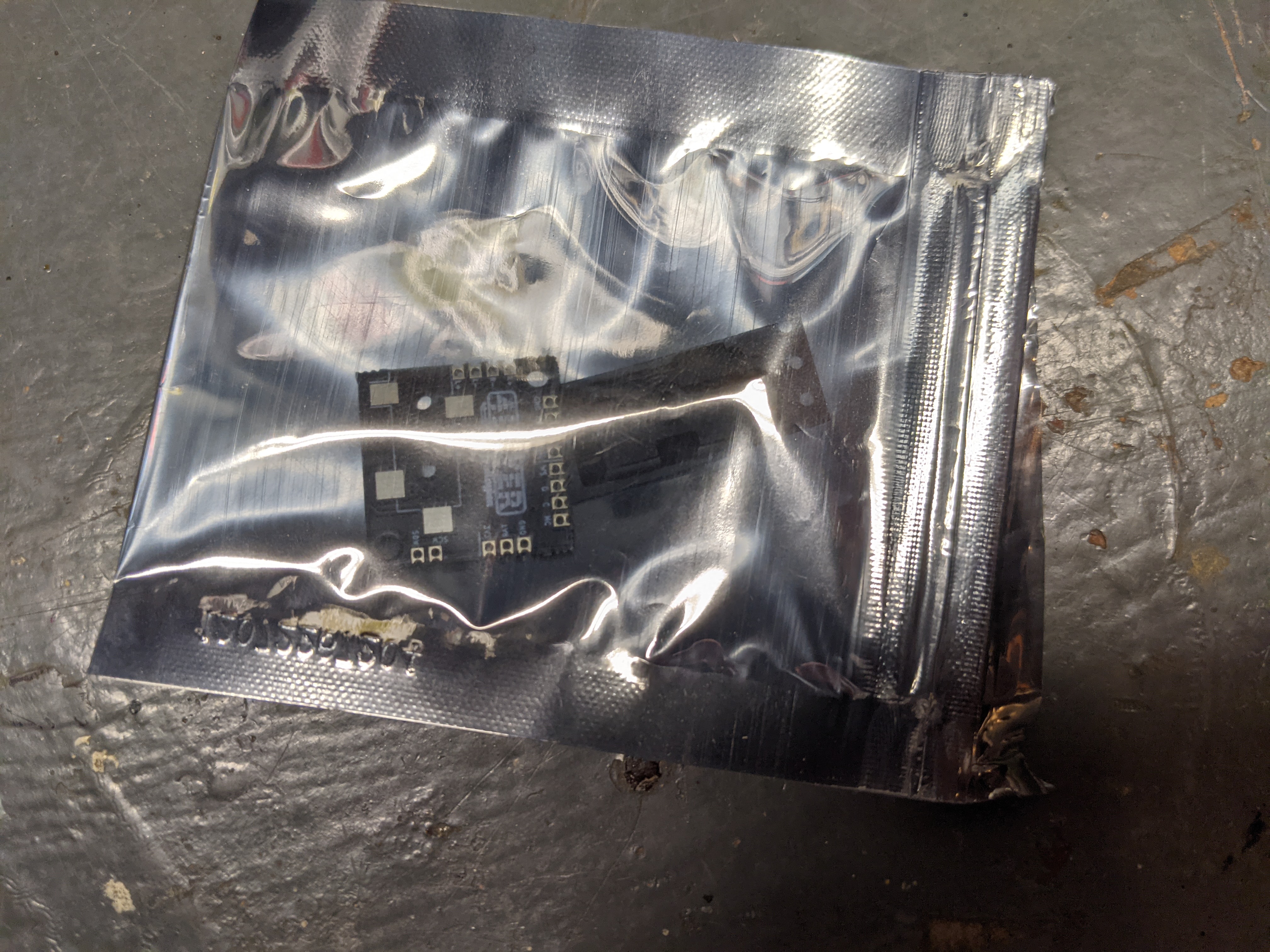
Hey guys. I need some help with the screen. Here is the driver board from 4layertech.
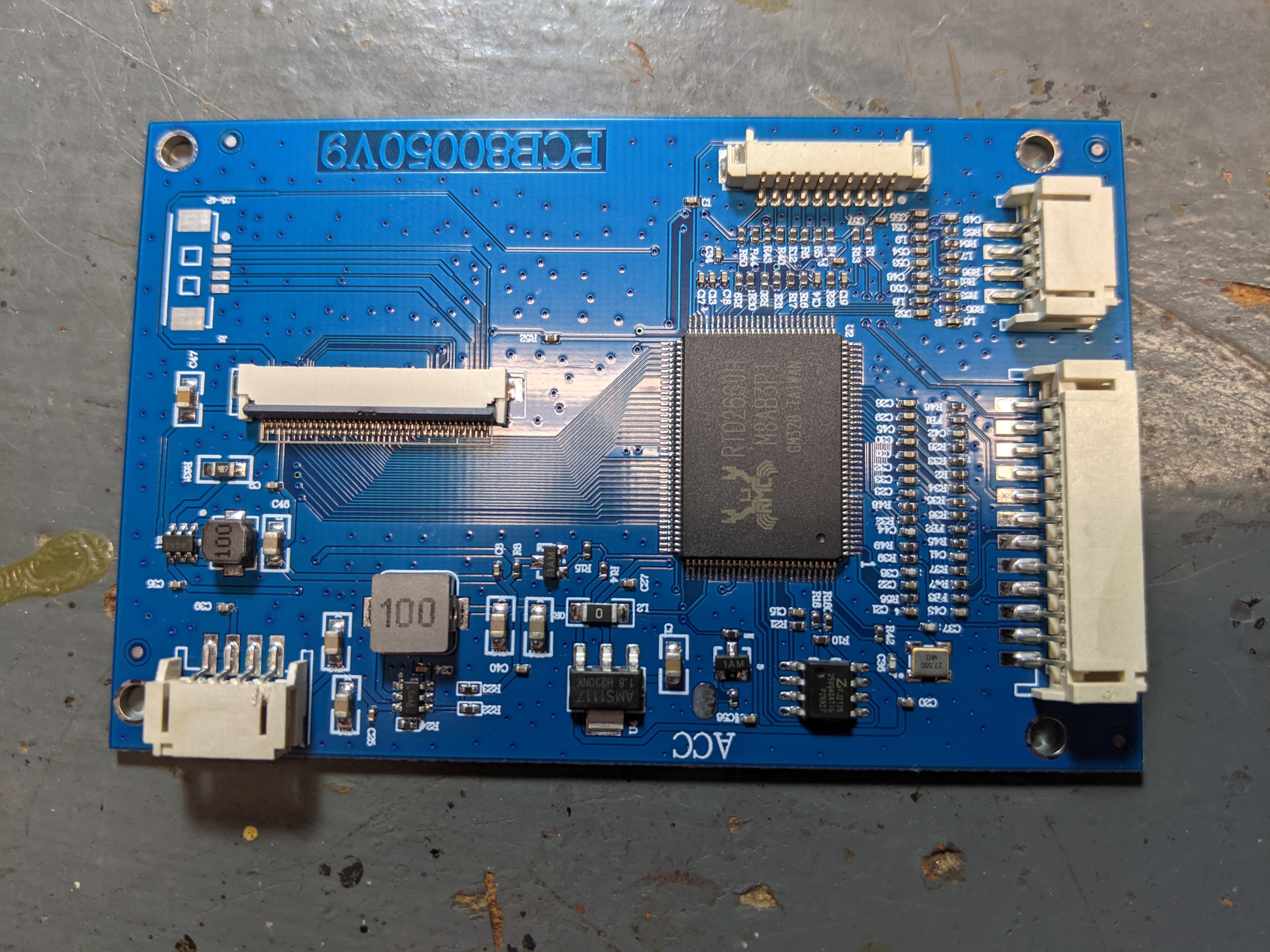
I plan on using VGA, but I'm not sure how I'm going to do that, so I have a couple of questions.
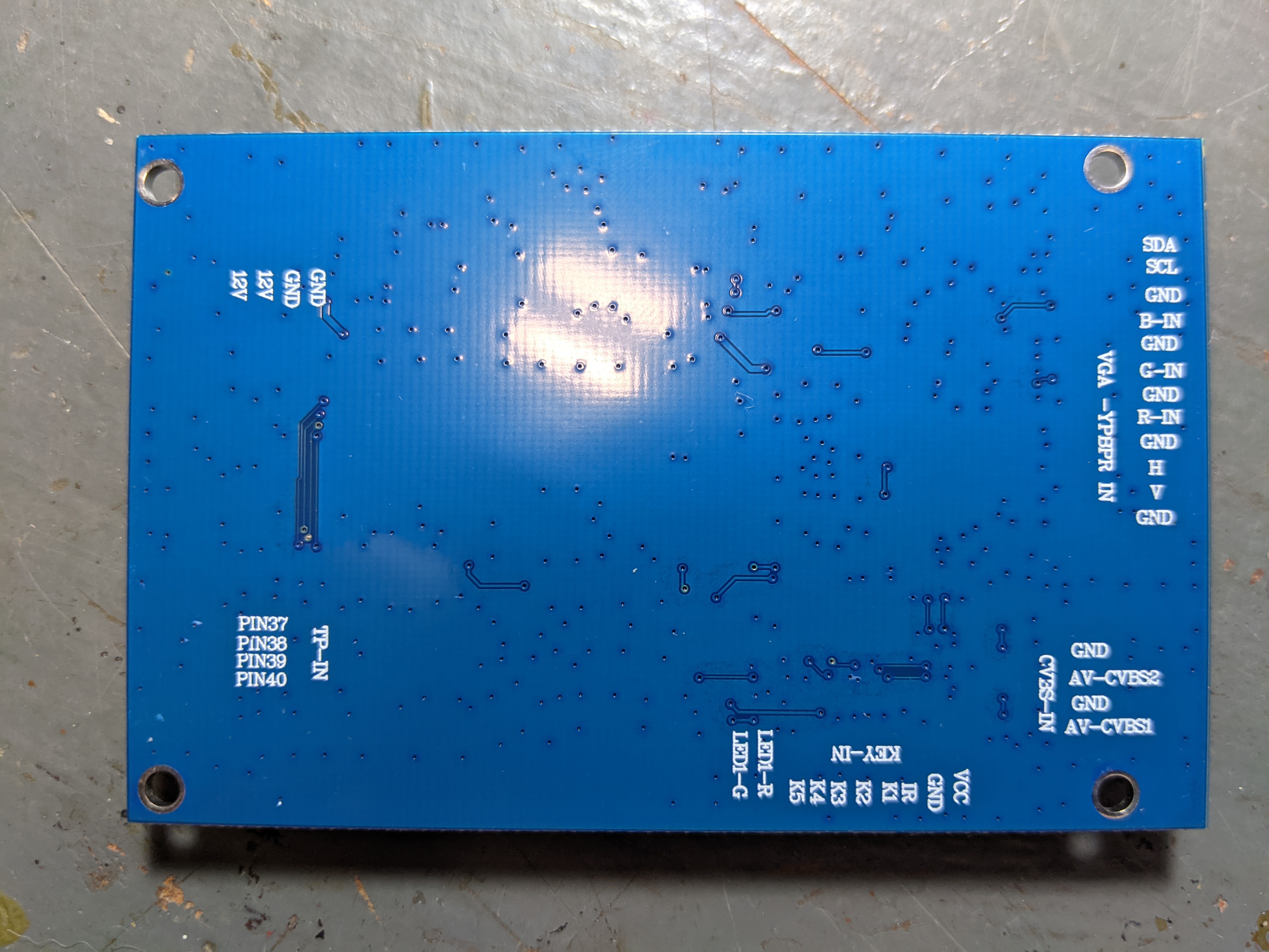
1. Where is the voltage input for the board? I see 12v, but the PMS Lite doesn't support that.
2. Is it okay to desolder the part with the pins for VGA and ypbpr, and just solder wires to the pads below?
3. Are SDA and SCL necessary? I see them on the screen driver board and on VGA pinout diagrams, but not on the Wii trimming guide.
4. Are all of the ground points on the part with the pins for VGA and ypbpr required to connect? I see 5 of them.
I plan on using VGA, but I'm not sure how I'm going to do that, so I have a couple of questions.
1. Where is the voltage input for the board? I see 12v, but the PMS Lite doesn't support that.
2. Is it okay to desolder the part with the pins for VGA and ypbpr, and just solder wires to the pads below?
3. Are SDA and SCL necessary? I see them on the screen driver board and on VGA pinout diagrams, but not on the Wii trimming guide.
4. Are all of the ground points on the part with the pins for VGA and ypbpr required to connect? I see 5 of them.
1.Hey guys. I need some help with the screen. Here is the driver board from 4layertech.
View attachment 27434
View attachment 27435
I plan on using VGA, but I'm not sure how I'm going to do that, so I have a couple of questions.
1. Where is the voltage input for the board? I see 12v, but the PMS Lite doesn't support that.
2. Is it okay to desolder the part with the pins for VGA and ypbpr, and just solder wires to the pads below?
3. Are SDA and SCL necessary? I see them on the screen driver board and on VGA pinout diagrams, but not on the Wii trimming guide.
4. Are all of the ground points on the part with the pins for VGA and ypbpr required to connect? I see 5 of them.
2. Yes you can desolder the plastic connector, just don't breath in that smoke
3. SDA and SCL are not necessery, but correct me if im wrong.
4. You could do just one ground, but it would give you some ugly wavy line so its recommended to twist the video lines with ground to get rid of it
Edit: Fixed a mistake in 1.
Last edited:
For 1, it should be 3v3, not 5v1.
View attachment 27438
2. Yes you can desolder the plastic connector, just don't breath in that smoke
3. SDA and SCL are not necessery, but correct me if im wrong.
4. You could do just one ground, but it would give you some ugly wavy line so its recommended to twist the video lines with ground to get rid of it
SDA and SCL are not needed for the screen driver board, those pads should be ignored
- Joined
- Mar 26, 2023
- Messages
- 134
- Likes
- 95
Thanks for the info guys. I just saw the info on the 4layerwebsite and was about say something.For 1, it should be 3v3, not 5v
Last edited:
- Joined
- Mar 26, 2023
- Messages
- 134
- Likes
- 95
Hello again. Sorry for the double post, that was a reply from before.
The RVL-PD is out of stock, but I just want to test the PMS Lite without it. I have one question for that. If I want to wire a power button without the PD can I just connect one side of the button to the BTN line, and one to ground? Thanks.
The RVL-PD is out of stock, but I just want to test the PMS Lite without it. I have one question for that. If I want to wire a power button without the PD can I just connect one side of the button to the BTN line, and one to ground? Thanks.